

Page 1
Page 2

Table of Contents
Chapter 1 Introduction......................................................................................................1
1.1 Important Safety Precautions .......................................................................................................... 1
1.2 Important Notices............................................................................................................................ 3
1.3 Product Functions ........................................................................................................................... 3
1.4 Package Contents ............................................................................................................................ 3
1.5 Pull down the base .......................................................................................................................... 3
1.6 Viewing Angle Adjustment............................................................................................................. 4
1.7 Detaching main body from Its Stand............................................................................................... 4
1.8 Interface for Arm Applications ....................................................................................................... 4
Chapter 2 Installation.......................................................................................................5
2.1 Product Description......................................................................................................................... 5
2.2 System Installation:......................................................................................................................... 6
Chapter 3 Operation Instruction.......................................................................................7
3.1 Remote Control ............................................................................................................................... 7
3.2 Advanced Setting ............................................................................................................................ 8
Chapter 4 Technical Information ................................................................................... 11
4.1 Specifications................................................................................................................................ 11
4.2 Standard Timing Table.................................................................................................................. 13
Chapter 5 Other Information.......................................................................................... 13
5.1 Specifications................................................................................................................................ 13
Chapter 6 Troubleshooting............................................................................................. 14
Chapter 1 Introduction
Thank you for your purchase of this product. With this product you can use your computer monitor to watch
TV/CATV, VCR, LD, and DVD or play a video game. Without turning on your computer, the system set up is very
easy and there is no additional requirement for hardware or software. You don't need to learn a complicated set-up
procedure and you can enjoy your product with just Plug & Play
TM
.
1.1 Important Safety Precautions
Electricity is used to perform many useful functions, but it can also cause personal injuries and property damage if
improperly handled. This product has been engineered and manufactured with the highest priority on safety.
However, improper use can result in electric shock and/or fire. In order to prevent potential danger, please observe
the following instructions when installing, operating and cleaning the product. To ensure your safety and prolong the
service life of your LCD color TV product, please read the following precautions carefully before using the product.
Read instructions—All operating instructions must be read and understood before the product is operated.
Keep this manual in a safe place—These safety and operating instructions must be kept in a safe place for future
reference.
Observe warnings—All warnings on the product and in the instructions must be observed closely.
Follow instructions—All operating instructions must be followed.
Attachments—Do not use attachments not recommended by the manufacturer. Use of inadequate attachments
can result in accidents.
Power source—This product must operate on a power source specified on the specification label. If you are not
sure of the type of power supply used in your home, consult your dealer or local power company. For units
designed to operate on batteries or another power source, refer to the operating instructions.
Power cord protection—The power cords must be routed properly to prevent people from stepping on them or
objects from resting on them. Check the cords at the plugs and product.
1
Page 3

If the AC adapter is misplaced or needs to be replaced, obtain the same type of adapter.
Overloading—Do not overload AC outlets or extension cords. Overloading can cause fire or electric shock.
Entering of objects and liquids—Never insert an object into the product through vents or openings. High voltage
flows in the product, and inserting an object can cause electric shock and/or short internal parts. For the same
reason, do not spill water or liquid on the product.
Servicing—Do not attempt to service the product yourself. Removing covers can expose you to high voltage and
other dangerous conditions. Request a qualified service person to perform servicing.
Repair—If any of the following conditions occurs, unplug the power cord from the AC outlet, and request a
qualified service person to perform repairs.
a. When the power cord or plug is damaged.
b. When a liquid was spilled on the product or when objects have fallen into the product.
c. When the product has been exposed to rain or water.
d. When the product does not operate properly as described in the operating instructions. Do not touch the
controls other than those described in the operating instructions. Improper adjustment of controls not described
in the instructions can cause damage, which often requires extensive adjustment work by a qualified
technician.
e. When the product has been dropped or damaged.
f. When the product displays an abnormal condition. Any noticeable abnormality in the product indicates that the
product needs servicing.
Replacement parts—In case the product needs replacement parts, make sure that the service person uses
replacement parts specified by the manufacturer, or those with the same characteristics and performance as the
original parts. Use of unauthorized parts can result in fire, electric shock and/or other danger.
Safety checks—Upon completion of service or repair work, request the service technician to perform safety
checks to ensure that the product is in proper operating condition.
Polarization—This AC adapter may be equipped with a polarized alternating current line plug (a plug having one
blade wider than the other). This plug will fit into the power outlet only one way. This is a safety feature. If you are
unable to insert the plug fully into the outlet, try reversing the plug. If the plug should still fail to fit, contact your
electrician to replace your obsolete outlet. Do not defeat the safety purpose of the polarized plug.
For use only with AC adapter, Li-shin LSE9901B1260.
1.1.1 FCC Statement Warning
This equipment has been tested and found to comply with the limits for a Class B digital device, pursuant to Part 15
of the FCC Rules. These limits are designed to provide reasonable protection against harmful interference in a
residential installation. This equipment generates, uses, and can radiate radio frequency energy, and if not installed
and used in accordance with the instruction, may cause harmful interference to radio communications. However,
there is no guarantee that interference will not occur in a particular installation. If this equipment does cause harmful
interference to radio or television reception, which can be determined by turning the equipment off and on, the user
is encouraged to try to correct the interference by one or more of the following measures:
• Reorient or relocate the receiving antenna.
• Increase the separation between the equipment and the receiver.
• Connect the equipment into an outlet on a circuit different from that to which the receiver is connected.
• Consult the dealer or an experienced radio/TV technician for help.
Warning
Use only shielded signal cables to connect I/O devices to this equipment. You are cautioned that changes or
modifications not expressly approved by the party responsible for compliance could void your authority to operate
the equipment.
1.1.2 Canadian DOC Notice
This Class B digital apparatus meets all requirements of the Canadian Interference-Causing
Equipment Regulations.
Cet appareil numérique de la classe B repecte toutes les exigences du Règlement sur le matériel
brouilleur du Canada.
2
Page 4
1.2 Important Notices
Please use the product under a normal environment
1. Try to avoid the following circumstances.
* Heat or direct sunlight places
* Location with huge magnetic field
2. For the unauthorized person, please don't service this product: otherwise the damage caused by
unauthorized servicing is not covered by warranty.
3. Unplug this product from AC outlet and remove batteries from remote control when this product is left
unused for a long time.
* Unstable or vibrational places
* Exposure to rain or moisture places
1.3 Product Functions
With the advanced video processing technology, the TV composite VIDEO, S-VIDEO signal can be
displayed on a PC monitor.
Double scan conversion (15.75 KHz to 31.5 Khz).
With built-in audio loop the audio signal coming from the PC can pass through to PC speakers in any
circumstance.
Full screen, true color display.
TV systems: NTSC system.
Built-in TV tuner for receiving terrestrial or cable TV.
Easy operation - With one button to switch signals coming from composite VIDEO, S-VIDEO,
COMPONENT VIDEO, CABLE/TV or PC.
Automatic channel scan to detect the program channels.
On screen display operation with remote controller.
MTS supported for NTSC system. (Available in North America & Taiwan markets.)
1.4 Package Contents
As you unpack the product, please make sure the following items were included. If any of these items are
missing, call your local agencies.
▪ Main body x1 ▪ Audio cable x1 ▪ Remote control x1
▪ Power supply x1 ▪ User manual x1 ▪ Power cord x1
▪ VGA cable x1 ▪ AAA batteries x2
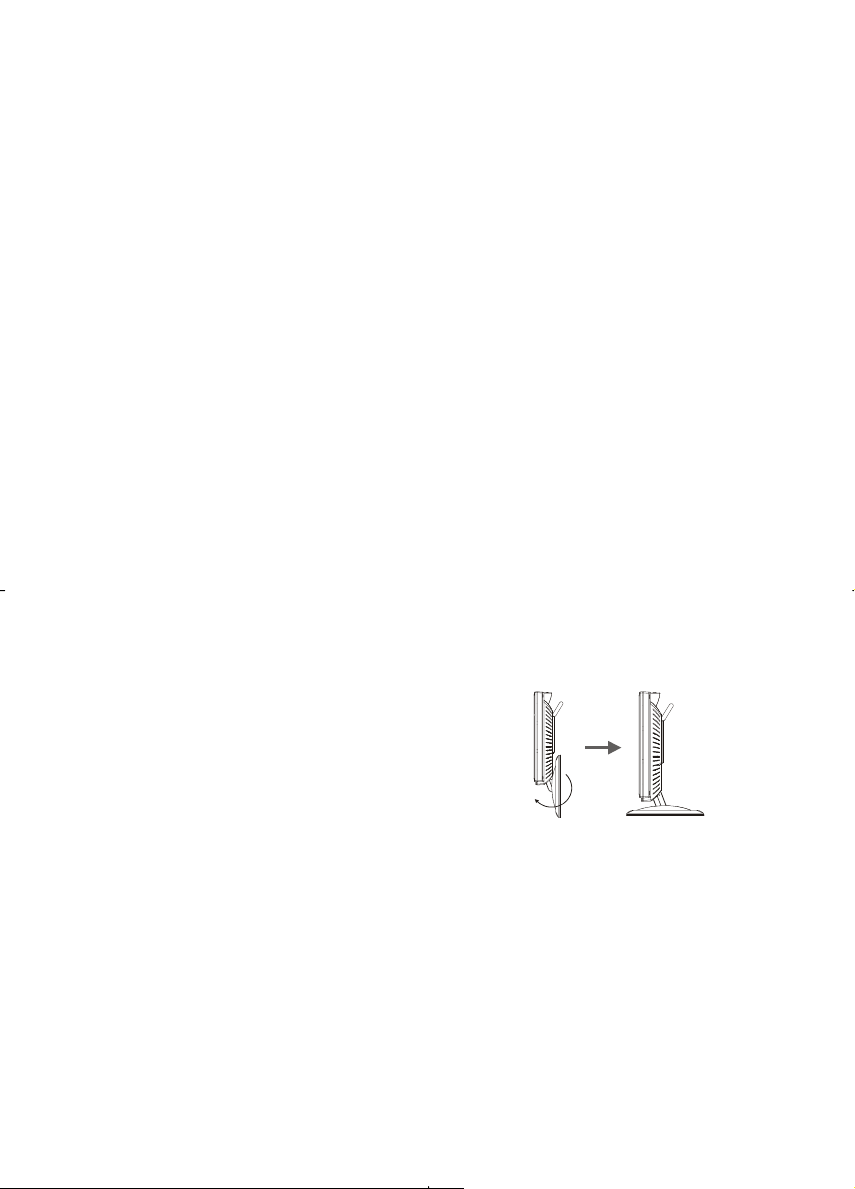
1.5 Pull down the base
When you open the box to take the product out, pull
down the base first (See figure 1-1)
3
Figure 1-1
Page 5
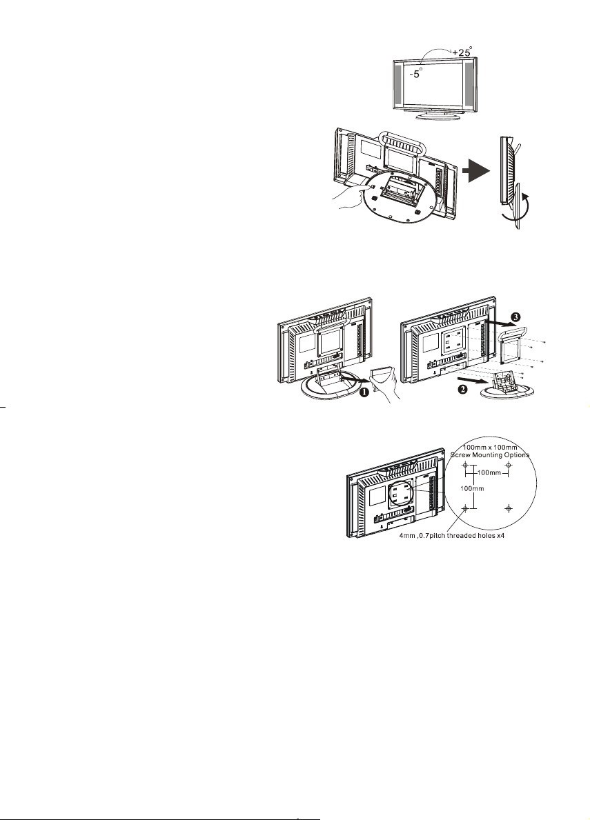
1.6 Viewing Angle Adjustment
This product is designed to allow users to have a
comfortable viewing angle. The viewing angle can be
adjusted from -5°to +25°. (See Figure 1-2).
Figure 1-2
When you want to close the base and body to 90°, you need to
release a button from 25°. (See fig. 1-3)
Warning: Do not force the L CD Monitor over its maxim um viewing angle settings as stated above. Attempting this
will result in damage to the Monitor and Monitor stand.
Figure 1-3
1.7 Detaching main body from Its Stand
1. Remove the rear cover from neck (See
Figure 1-4)
2. Unscrew screws of the hinge bracket
3. Remove the stand from main body
Figure 1-4
1.8 Interface for Arm Applications
Before installing to mounting device, refer to Fig.1-4.
The rear of this LCD display has four integrated 4 mm, 0.7
pitches threaded nuts, as well as four 5 mm access holes in the
plastic covering as illustrated in Figure 1-5. These
specifications meet the VESA Flat Panel Monitor Physical
Mounting Interface Standard (paragraphs 2.1 and 2.1.3,
version 1, dated 13 November 1997).
Note :Please using Ø 4mm x 8mm (L) screw for this application.
4
Figure 1-5
Page 6

Chapter 2 Installation
2.1 Product Description
2.1.1 Front view of main body
1
2
3
4
5
6
7
Indicator for
Power
IR receiver
Power
Menu
Channel
Volume
Source
LED lights Green color --- Power is ON.
LED lights Orange --- Monitor is in "Power Saving Mode".
LED is off --- Power is OFF.
IR receiver (Remote).
Turn on or off the main body.
Open or Close the OSD menu.
Select the next lower channel / higher channel (TV/AV mode) ; OSD
function for selecting (PC mode).
Lower / Raise the sound volume (TV/AV mode) ; OSD function for
adjusting (PC mode).
Selection CABLE/TV, AV-1(S –VIDEO), AV-2(C-VIDEO) or PC.
Figure 2-1
Figure 2-2
2.1.2 Rear view of main body
1 RF in
2 VGA input
4 AV1-in
3 AV2-in
5 Phone in
6 DC in
7 Kensington Lock hole
Connects to antenna or cable TV signal.
Use the 15-pin VGA cable in the package contents.
For composite video or S-video input and audio.
For component Video input and audio.
Connect the audio from sound card to PHONE IN.
Connect to your 12V power supply.
It can be locked with Kensington lock.
Figure 2-3
5
Page 7

2.2 System Installation:
Refer to the example closest to your configuration.
Turn off the power of all devices before connection. For audio connection, use RCA audio (L+R)
connector. For video connection, choose either RCA video connector or s-video connector.
For connection to monitor alone omit those connections associated with PC.
6
Page 8

Chapter 3 Operation Instruction
3.1 Remote Control
7
Page 9

3.2 Advanced Setting
3.2.1 TV/AV
The OSD shown below displays when you press "MENU" (on main body) or "►" (on remote control) button.
1. Press "
VIDEO, SYSTEM, C.C., V-CHIP.
2. Press "
body) or "←, →" (on remote control) button to adjust content.
AUDIO: Treble, Bass and Balance.
VIDEO: Brightness, Picture, Color, Hue and Sharp.
SYSTEM: MTS, Language, Sleep, TV/CATV, Channel search, Channel memory, Fine tune and Recall.
C.C. (Closed Caption)
V-CHIP: TV, MPAA, Change Pin.
" (on main body) or "←, →" (on remote control) button to adjust content. Select AUDIO,
" (on main body) or "↑, ↓" (on remote control) button to select item. Then press " " (on main
AUDIO
TREBLE Lower or raise the treble for sound.
BASS Lower or raise the bass for sound.
BALANCE Adjust the speaker balance on L/R.
VIDEO
BRIGHTNESS
PICTURE
COLOR Lower or raise the color intensity.
HUE Toward purple or green adjusting.
SHARP Adjust the picture for soft or sharp.
SYSTEM
MTS Select different type for Audio.
LANGUAGE Select the language for the screen.
SLEEP Select the sleep timer..
TV/CATV Select TV or CATV.
CH. SEARCH Scan program channels automatically.
CH. MEMORY Add or remove a channel.
FINE TUNE
RECALL Recall the video setting to original.
CLOSED CAPTION
CLOSED CAPTION Select different system in caption.
Increases or decreases the brightness of
the image.
Increases or decreases the contrast of the
image.
0.05 MHz for pre time (±2.0 MHz)
V-CHIP
TV Sets the TV grade.
MPAA Sets the MPAA grade.
CHANGE PIN Changes the pin number. The original pin
8
number is “1234”, If you forget your pin,
please follow the process:
1. Turn off the power on main body.
2. Press ” TV、AV、PC ” key on main
body and keep it depressed.
3. Turn on the power on main body.
4. Reset it.
Page 10

p
3.2.2 PC
The OSD shown below displays when you press "MENU"(on main body) or "►" button. (on remote control)
Press " " (on main body) or "↑, ↓" (on remote control) button to select item.
Then press "
adjust content.
" (on main body) or "←, →" (on remote control) button to
After you choose the “PIP”, then press “MENU” (on main body) or “►” (on
remote control) to enter the second page and finish adjustment to
“MENU” (on main body) or “►” (on remote control) return to main menu.
ress
When you choose the user mode in color temperature, then press “MENU” (on
main body) or “►” (on remote control) to enter second page to adjust the
R,G,B and finish adjustment to press “MENU” (on main body) or “►” (on
remote control) return to main menu.
9
Page 11

3.2.3 PC OSD function description
Icon Function Function Description
Brightness
Contrast
H-Position
V-Position
Auto Adjustment
Phase
Clock
Picture in picture
Source
Audio
Scale
H-Pos.
V-Pos.
OSD H-Position
OSD V-Position
Graph Text
Recall
Language
Color
Temperature
Save Exit
Icon Description
9300
6500
USER
Set CIE coordinated at 9300°K color temperature.
Set CIE coordinated at 6500°K color temperature.
There are 3 colors (Red, Green, Blue) for user to adjust from OSD menu.
R
G
B
This function increases or decreases the brightness of the image.
This function increases or decreases the difference between the dark and light
color.
This function shifts the entire display image left or right.
This function shifts the entire display image up or down.
This function will adjust the display size automatically to fit full screen.
This function is available to adjust the focus and clarity of the display.
This function carries a frequency-tracking feature that offers the user to have
better stability and clarity. Increasing Clock value can be up to +50 scales. The
number of decreasing Clock (minus) depends on the input timing.
The function is to open video picture in screen.
This function is to select video source.
This function is to select sound from PC (Main) or Video (Sub).
This function is to choose 4 scales size for picture.
This function moves the video window left or right.
This function moves the video window up or down.
This function moves the OSD menu window left or right.
This function moves the OSD menu window up or down.
This function is to choose a display that allows maximum graphics text quality.
The resolution selection can either be 640 x 400 or 720 x 400. Please refer to
Chapter 3 “ Standard Timing” Table for of different timing modes.
The recall function will return all adjusted parameters to factory preset values.
Three OSD languages options are available:
English, Japanese, Chinese.
This function selects a different color temperature. Please see the diagram below
for function and description.
Saves the values of this setting and exits the OSD menu function.
Adjust Red color on screen.
Adjust Green color on screen.
Adjust Blue color on screen.
10
Page 12

Chapter 4 Technical Information
4.1 Specifications
LCD Panel
Size 15" (43 cm)
Display Type Active matrix color TFT LCD
Resolution 1024 x 768
Display Dot 1024 x (RGB) x 768
Display Area (mm) 304.1 x 228 (H x V)
Brightness 450 cd/m
Contrast Ratio 400:1 (typical)
Response Time
Lamp Voltage 590 Vrms (typical)
Lamp Current 8 mA rms. (typical)
Viewing Angle Vertical: -75° ~ +75°
Display colors
Video
Input Signal Analog RGB 0.7Vp-p
Input Impedance 75 Ohm ± 2%
Polarity Positive, Negative
Amplitude 0 - 0.7 ± 0.05 Vp
Multi-mode Supported Horizontal Frequency: 30 ~ 60 KHz
Speaker
Control
Power switch (hard and soft types) On/Off switch with LED indicator
OSD (On Screen Display)
Brightness Digital
Contrast Digital
Horizontal Position Digital
Vertical Position Digital
Phase Digital
Clock Digital
Display Mode Setup Use EEPROM to save settings in memory
OSD Format 20 characters x 9 rows
2
(typical)
Ta=25°C 16ms (Tr+Tf )
Horizontal: -70° ~ +70°
16.7M with frame rate conversion or Dithering
Vertical Frequency: 55 ~ 75 Hz
3W, 8 OHM
11
Page 13

m
m
m
Power Management
Mode Power Consumption* AC Input LED Color
On 60W maximu
Off 5W maximu
Soft switch off 5W maximu
Disconnected 5W maximum 240 VAC
* Meeting VESA DPMS requirements measured from AC Input end of AC power cord.
Sync Input
Signal Separate TTL compatible horizontal and vertical synchronization
Polarity Positive and negative
Plug & Play
External Connection
Supports VESA DDC1 and DDC2B functions
Power Input (AC input) AC socket
Video Cable 1.5M with 15-pin D-sub connector
Audio Cable 1.5M with Stereo Jack
Environment
Operating Condition:
Storage Condition:
Power Supply (AC Input)
Temperature 5°C to 35°C/41°F to 95°F
Relative Humidity 20% to 80%
Temperature -20°C to 60° C/-4°F to140° F
Relative Humidity 5% to 85%
Input Voltage Single phase, 100 ~ 240VAC, 50 / 60 Hz
Input Current 1.2 A maximum
240 VAC Green
240 VAC Orange
240 VAC Dark
Orange: Standby, Suspend, Off
Dark: DC Power off
Pin Assignment
1
5
6
Signal Signal
PIN Description PIN Description
11
2
3
4
1
15
5
6
7
8
10
Red
Green
Blue
NC
Digital GND
Red Rtn
Green Rtn
Blue Rtn
9
10
11
12
13
14
15
+5V
Hot Plug Detect
NC
SDA
H. Sync.
V. Sync.
SCL
12
Page 14

4.2 Standard Timing Table
If the selected timing is NOT included in table below, this LCD monitor will use the most suitable available timing.
Nominal
Mode Resolution Total
VGA
SVGA
XGA
DOS* 720x400@70Hz 900 x 449 31.469 N 70.087 P 28.322
DOS 640x350@70Hz 800 x 449 31.469 P 70.087 N 25.175
640x480@60Hz 800 x 525 31.469 N 59.940 N 25.175
640x480@72Hz 832 x 520 37.861 N 72.809 N 31.500
640x480@75Hz 840 x 500 37.500 N 75.00 N 31.500
800x600@56Hz 1024 x 625 35.156 N/P 56.250 N/P 36.000
800x600@60Hz 1056 x 628 37.879 P 60.317 P 40.000
800x600@72Hz 1040 x 666 48.077 P 72.188 P 50.000
800x600@75Hz 1056x625 46.875 P 75.000 P 49.500
1024x768@60Hz 1344x806 48.363 N 60.004 N 65.000
1024x768@70Hz 1328x806 56.476 N 70.069 N 75.000
1024x768@75Hz 1312x800 60.023 P 75.029 P 78.750
Frequency
(KHz)
Horizontal Vertical
VESA MODES
IBM MODES
Sync
Polarity
Nominal
Freq.
(Hz)
Sync
Polarity
Nominal
Pixel
Clock
(MHz)
Chapter 5 Other Information
5.1 Specifications
POWER IN 12VDC 5A
VIDEO INPUT Composite /Component video RCA connector
S-VIDEO INPUT S-Video 4-pin mini DIN
AUDIO INPUT Stereo L+R RCA connectors
PHONE IN Phone Jack 3.5
RF IN F-Female connector for NTSC system
VGA INPUT D-Sub 15 pin connector
Power Consumption 60W maximum
Operating Temperature 5 ~ 35°C
Operating Humidity 5% ~ 80%
IR Control 28 Buttons (AAA batteries x2)
Dimensions 430 (W) x 325.5 (H) x 198 (D) mm
Net Weight
Gross Weight
4.0 ± 0.3 kg
5.8 ± 0.3 kg
13
Page 15

Chapter 6 Troubleshooting
This LCD Monitor was pre-adjusted using factory standard VGA timings. Due to the output timing
differences among various VGA cards in the market, users may initially experience an unstable or unclear
display whenever a new display mode or new VGA card is selected.
Attention
This LCD Monitor Supports Multiple VGA Modes.
Refer to the Standard Timing Table for a listing of modes supported by this LCD Monitor.
PROBLEM Picture is unclear and unstable
The picture is unclear and unstable, please perform the following steps :
1. Enter PC to “Shut Down Windows” status while you’re in MS-Windows environment.
2. Check the screen to see if there are any black vertical stripes. If there are, take advantage of the “Clock”
function in OSD menu and adjust (by increment or decrement numbers) until those bars disappear.
3. Move to “Phase” function in OSD menu again and adjust the monitor screen to the most clear display.
4. Click “No” on “Shut Down Windows” and back to the normal PC operating environment.
PROBLEM There is no picture on LCD Monitor
If there’s no picture on the LCD Monitor, perform the following steps:
1. Make sure the power indicator on the LCD Monitor is ON, all connections are secured, and the system is
running on the correct timing. Refer to Chapter 3 for information on timing.
2. Turn off the LCD Monitor and then turn it back on again. If there is still no picture, press the Adjustment
Control button several times.
3. If step 2 doesn’t work, connect your PC system to another external CRT. If your PC system Functions
properly with a CRT Monitor but it does not function with the LCD Monitor, the output timing of the VGA
card may be out of the LCD’s synchronous range. Please change to an alternative mode listed in the
Standard Timing Table or replace the VGA card, and then repeat steps 1 and 2.
PROBLEM There is no picture on LCD Monitor
If you have chosen an output timing that is outside of the LCD Monitor’s synchronous range (Horizontal: 30 ~
60 KHz and Vertical: 55 ~ 75 Hz), the OSD will display an “Over Range” message. Choose a mode that is
supported by your LCD Monitor.
PROBLEM The IR control can't control product
Make sure if batteries are installed they are not weak batteries
If you still have difficulties you can't resolve using the tips described above, unplug and plug in the AC cord to
reset your product. Otherwise, call your local representative for servicing.
Also, if the signal cable is not connected to LCD monitor at all or properly, the monitor screen will display a
message “No Signal”.
14
 Loading...