

Page 1
OPERATI ONS MA NUA L
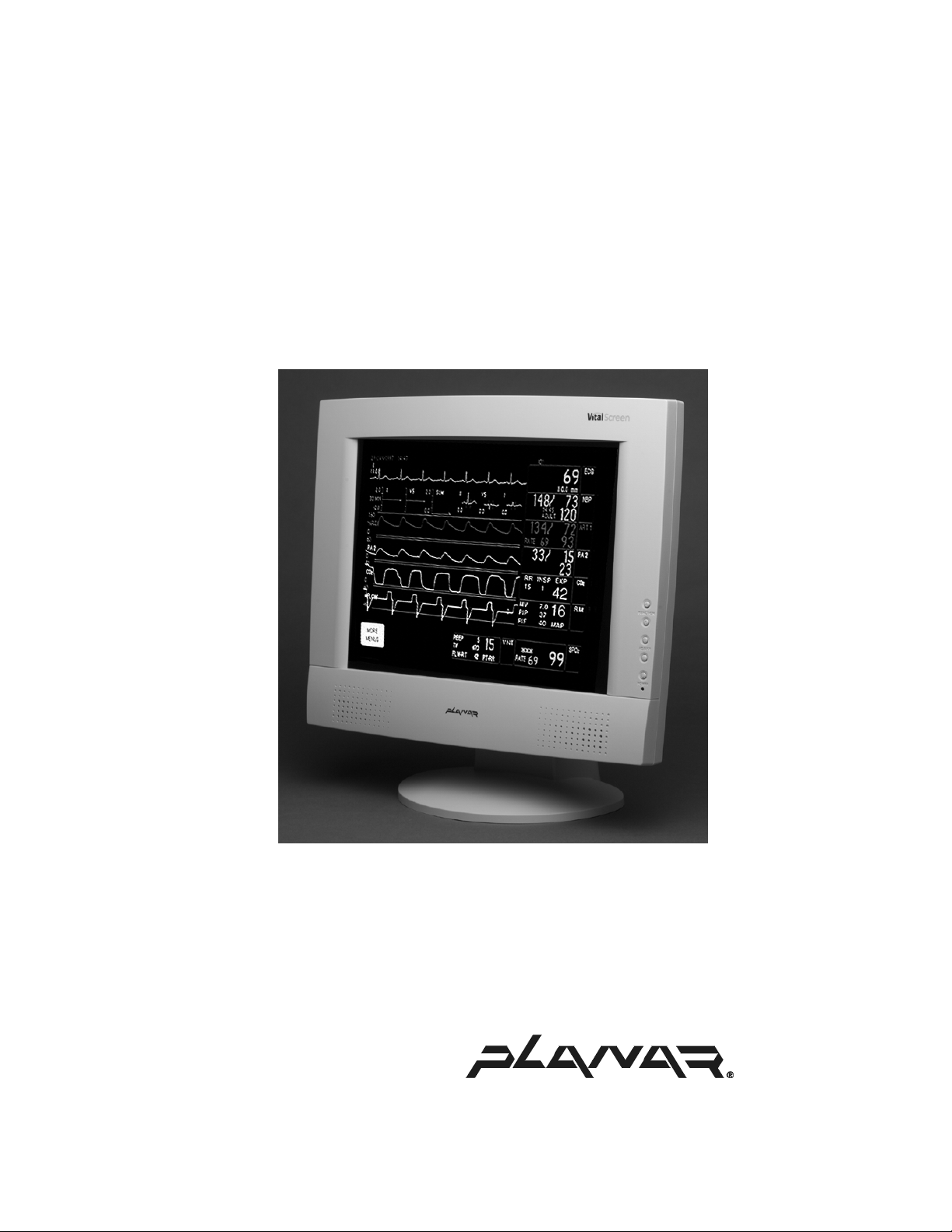
VitalScreen S Medically Certified Display
VSS15X / VSS15X-TR
Page 2

Planar Systems, Inc. © 2002. All rights reserved.
Information in this document has been carefully checked for accuracy; however,
no guarantee is given to the correctness of the contents. This document is subject
to change without notice. Planar provides this information as reference only.
Reference to other vendors’ pro d u c t do es n ot imply any recomm endation or
endorsement.
This document contains proprietary info rm a ti on protected b y copy right. No part of
this manual may be reproduced by any mechanical, electronic, or other means, in
any form, without prior written permission of the manufacturer.
Planar is a registered trademar k of Planar Systems, Inc.
DOCUMENT HISTORY
DATE DESCRIPTION
September 2002 Document number 020-0247-00 Rev. A
Page 3

Regulatory Compliance
This display has been tested and certified to international medical safety
standards IEC/EN 60601-1 and IEC/EN 60601-1-2, and is certified to
meet C22.2 No. 601.1-M1990 (C US Mark).
Because many medical offices are located in residential areas, the
medical display, in addition to meeting medical requirements, has
also been tested and found to comply with the limits for Federal
Communications Commission ( FCC) Class B computing devices in a
typically configured system. It is the system integrator or configurer’s
responsibility to test and ensure that the enti re system complies with
applicable electromagnetic compatibility (EMC ) laws.
Planar Systems, Inc. has made great efforts to support the medical
device industry, in particular, medical device manufacturers and medical
device system integrators. We offer state-of-the-art color displays that are
compliant with worldwide accepted medical device safety standards, and
for the European market, CE-marked displays based on compliance with
counsel directive 93/42/EEC commonly referre d to as the Medical Device
Directive (MDD). The following summarizes our qualification of these
displays as it relates to compliance with the MDD.
The European Medical Device Directive requires that the intended use
of the device be defined. The intended use of these displays is “to display
alphanumeric, graphic, and image data as inputted from any type of
medical device.” These displays do not provide a measurement function
in any way, and it is the device and systems manufactur er’s responsibility
to verify its function in the integrated device or system.
iii
The display was classified as required by the MDD according to Annex IX
of the directive and the medical device (MEDDEV) guidance available
at the time of classification. Because the display uses electrical energy
and has no direct patient connections andby itselfno medical utility,
the display is classified according to Rule 12 as an MDD Class I devicecomponent or ac c e s s o ry. The MDD stat es t h a t m anufa c tu r ers of Cla s s I
medical devices or acces sories shall satisfy the r equirements in regard
to design and manufacturing controls, that is, the applicable assessment
route to be used for CE-marking under the MDD, and it shall carry
the CE mark according to Annex XII of the directive, with no notified
body annotation.
The applicable safety standards for an MDD Class I display are
IEC/EN 60601-1:1900 along with Amendments 1 and 2. To help the
medical device designer evaluate the suitability of these displays,
Planar has also conducted EMC testing to I EC 60601-1-2 a s it can
be applied. The display with its power supply alone does not represent
a functional medical device. Hence, Planar configured a minimal
operating system to exercise the display. The resulting data are
made available to interested parti es.
The data are informative data, not certification data. Certification
data must be o btain ed by the device or system integrator according
to Article 12 of the MDD titled “Particular procedure for systems and
procedure packs.” Paragraph 2 clearly outli nes the device or system
integrator’s respons ibility in this matter.
VSS15X / VSS 15X-TR Operations Manual (020-0247-00 Rev. A)
Page 4

iv
In summary, Planar Systems, Inc. is CE-marking these di splays
under the Medical Device Directive, which establishes compliance to
the basic medical safety standards. However, EMC compliance can
only be accomplishe d in t he conf igured me d ical devi ce or system and
is the responsibility of the device or system man u facturer. Planar has
the necessary documentation such as IEC 60601-1 notified body and
other third-party test reports and certifications, a risk/hazard analysis,
an essential requ irements checklist, and the Planar International
Electrotechnical Commission (IEC) declaration of co nformity.
Planar Systems, Inc., located in Beaverton, Oregon, USA, is the
manufacturer of these displays in the meaning of the directive.
As required by the MDD in Article 14, Planar Systems, Inc., not
residing in the European Economic Area (EEA), has a European
representative, Planar Systems, Inc.Espoo, Finland.
In the opinion of Planar Systems, Inc. registration required to put t h is
device into commerce is the responsibility of the medical device/system
manufacturer, and Planar sup ports this requirement by providin g a
European commission (EC) declaration of conformity. If Planar supplies
a display to an end user, rather than a device manufacturer, it is the end
user’s responsibility to ensure continued compliance with the MDD of
the system in which the display is integrated.
For vigilance reporting as required under Article 10 of the MDD,
Planar Systems, Inc. will provide any information requested by
competent authority to support any reported incident investigation
by such an authority.
European Union Declaration of Conformity for Medical Applications
A Declaration of Conformity has been filed for this product. For
additional copies of the Declaration of Conformity document, contact
Planar Systems, Inc. and req uest documen t number 001-0014-07
“Declaration of Conformity.”
VSS15X / VSS15X-TR Operations Manual (020-0247-00 Rev. A)
Page 5

Contents
v
ABOUT THIS MANUAL
PRODUCT INFORMATION viii
vii
1 The VitalScreen S Display 1
Selecting a Workspace 1
Unpacking the Display 1
Identifying the Components 2
Adjusting th e Vi ew in g Angle 4
2 Installing the Display 5
Connecting the AC Power 5
Connecting the VGA Cable to the Computer 6
Connecting Stereo Speakers (optional) 7
Connecting the Optional Touch Screen 8
Power Management System 8
3 The Display Controls 9
Adjusting the Display 9
Using the Onscreen Display Main Menu 9
Appendix A: Technical Information 15
Appendix B: Su pported Timing
Appendix C: Troubleshooting
INDEX 19
DESCRIPTION OF WARRANTY 21
ORDERING INFORMATION 23
16
17
VSS15X / VSS 15X-TR Operations Manual (020-0247-00 Rev. A)
Page 6

vii
Page 7
About This Manual
Congratulations on your purchase of the VitalScreen S display!
This operations manual will help you set up, use, and maintain
models VSS15X (non-touch) and VSS15X-TR (resistive touch)
properly. Retain the manual for future reference.
Read this section carefully to learn how to handle the display
safely and clean it correctly. I t explains the symbols used on
the products an d the co nv en ti o ns used in this manual.
Chapter 1 provides an overview of the VitalScreen S display.
It lists the contents of the display package a nd identifies the
components of the display.
Chapter 2 explains how to install the display correctly and use
optional components.
Chapter 3 explains the menus and function controls built into
the display.
Technical information appears in Appendix A, supported timing
in Appendix B, and troubleshooting in Appendix C.
A description of warranty and ordering information are provided
at the back of t his manual.
Conventions
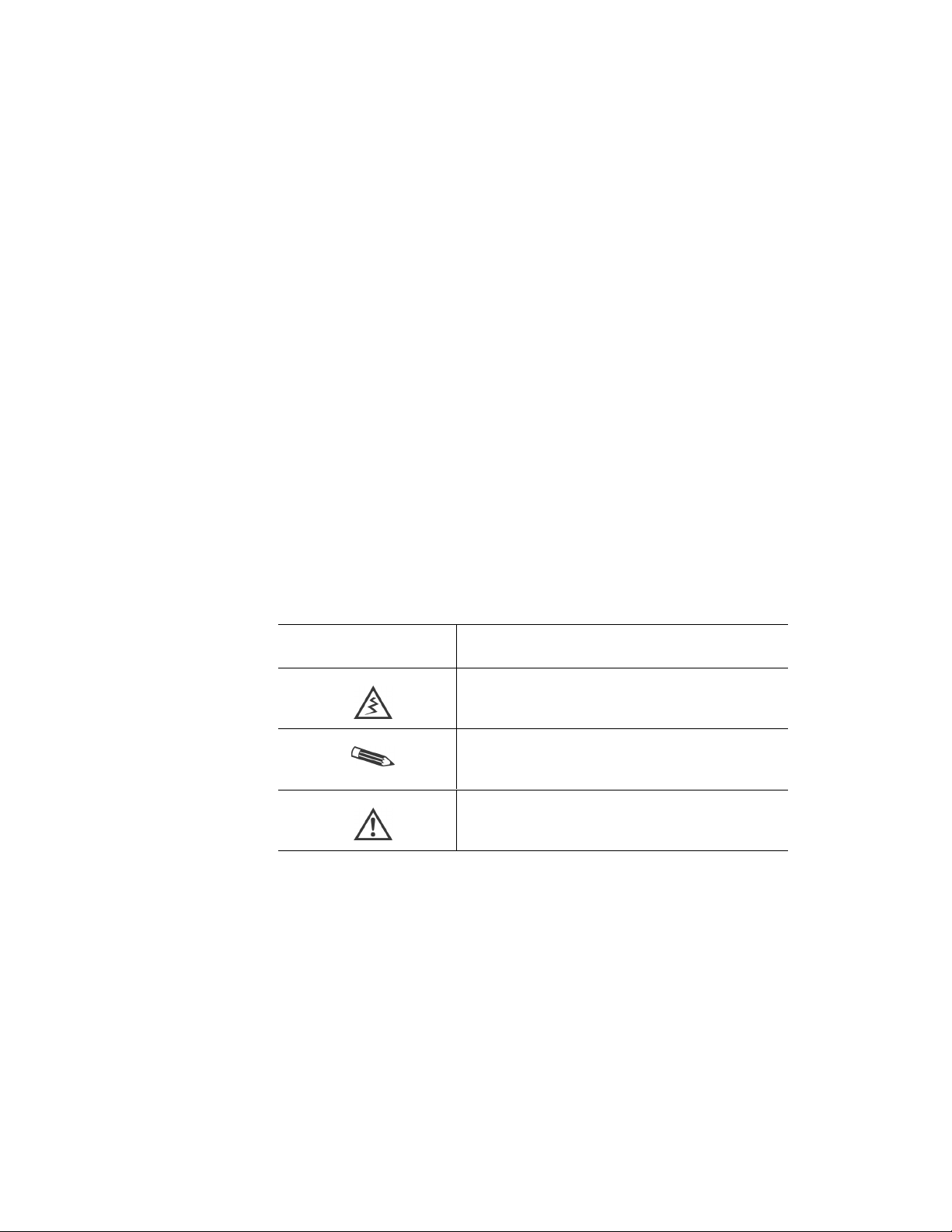
The VitalScreen S displa y docu mentation us es these conventi ons.
This convention…
Indicates…
A warning that can prevent injury to you,
such as electric shock.
A note of important information regarding
a particular topic or procedure.
A caution that can prevent potential damage
to hardware or software.
VSS15X / VSS 15X-TR Operations Manual (020-0247-00 Rev. A)
Page 8

viii | Product Information
Product Information
Safety Instructions
Store the display in its original shipping carton when it is not
in operation for extended periods of time. Also use the original
packing materials and carton when shipping the display.
• Do not place the display near a window. Exposing the
display to rain, water, moisture, or direct sunlight can
damage it.
• Do not place anyth ing on top of the display-to-computer
signal cord. Make sure the cord is placed where it will not
be s tepped on.
• Do not apply excessive pressure to the screen. Excessive
pressure may cause permanen t dam a ge to the display.
• Refer all servicing to qualified personnel to maintain your
warranty. The display and power supply units contain no
user-serviceable parts.
• Do not cover or obstru ct the venting holes on the back of
the display.
• Store the display in an environment with a temperature
range from −20 °C to 65 °C. Stor ing your display outside
that temperature range could result in permanent damage.
Do not expose the display to liquid or drop it. If the case
•
has been damaged, the unit may pose a shock or fire
hazard. Unplug the unit immediately and call customer
service for assistance.
• Replace any cord or cable that is frayed or damaged with
another of the same type and rating as supplied by Planar.
The safety and regulatory listings and certifications are
based on the cable supplied by Planar.
• Use only the powe r a dapter that has been t ested and
approved for use with this display product.
The power adapter must be plugged into a grounded
power outlet.
• Do not use the power adapter near inflammable anesthetics.
• Disconnect the display from the mains by pulling the mains
power cord/mains plug.
• Install the display near a wall outlet that is easily
accessible.
VSS15X / VSS15X-TR Operations Manual (020-0247-00 Rev. A)
Page 9

Product Information | ix
Cleaning Instructions
Use only the products listed bel o w fo r cleaning the dis pl ay. Th e
products di ffer for cleaning the screen and for cleaning the plastic
enclosure. Be sure you use only the specific products approved for
either the s cr een or the enclosur e.
Always apply the product to a clean nonabrasive cloth and then
wipe the screen or pla s t ic en c l os u r e. Cl eaners applied directly to
the display could leak inside a non-sealed unit and cause damage.
Be careful not to splash solvents on the screen or enclosure.
Recommended cleaning solution for screen
Use 70 percen t i s op r op y l a l coh o l. Thi s is th e only cleaning so l ution
approved for use on the non-touch screen (model VSS15X ) and the
touch scr een (m o d el VS S 1 5X- TR).
Do NOT use wate r o r s o lv ents (such as ket one, acetone ) and
aromatics (such as xylene, toluene).
To clean the screen
1
Switch the p ow er off.
2
Dampen a clean nonabrasive cloth with 70 percent
isopropyl alcohol.
3 Wipe the screen gently with the dampened cloth.
4
Dry the screen wi th a clea n nonabrasi v e cloth t o
remove any res idue.
Recommended cleaning solutions for plastic enclosure
You may also use 70 percent isopropyl alcohol to clean the
plastic enc l osure. Other wise, use only these approved pr odu c ts
to clean the en closure.
Cidex
•
• Clorox Clean-Up
• “Green soap” United States Pharmacopoeia (USP)
Plus
Formula 409
•
Sani-Cloth
•
Virustat TBQ
•
Do NO T use thes e product s on the s creen.
VSS15X / VSS 15X-TR Operations Manual (020-0247-00 Rev. A)
Page 10
x | Product Information
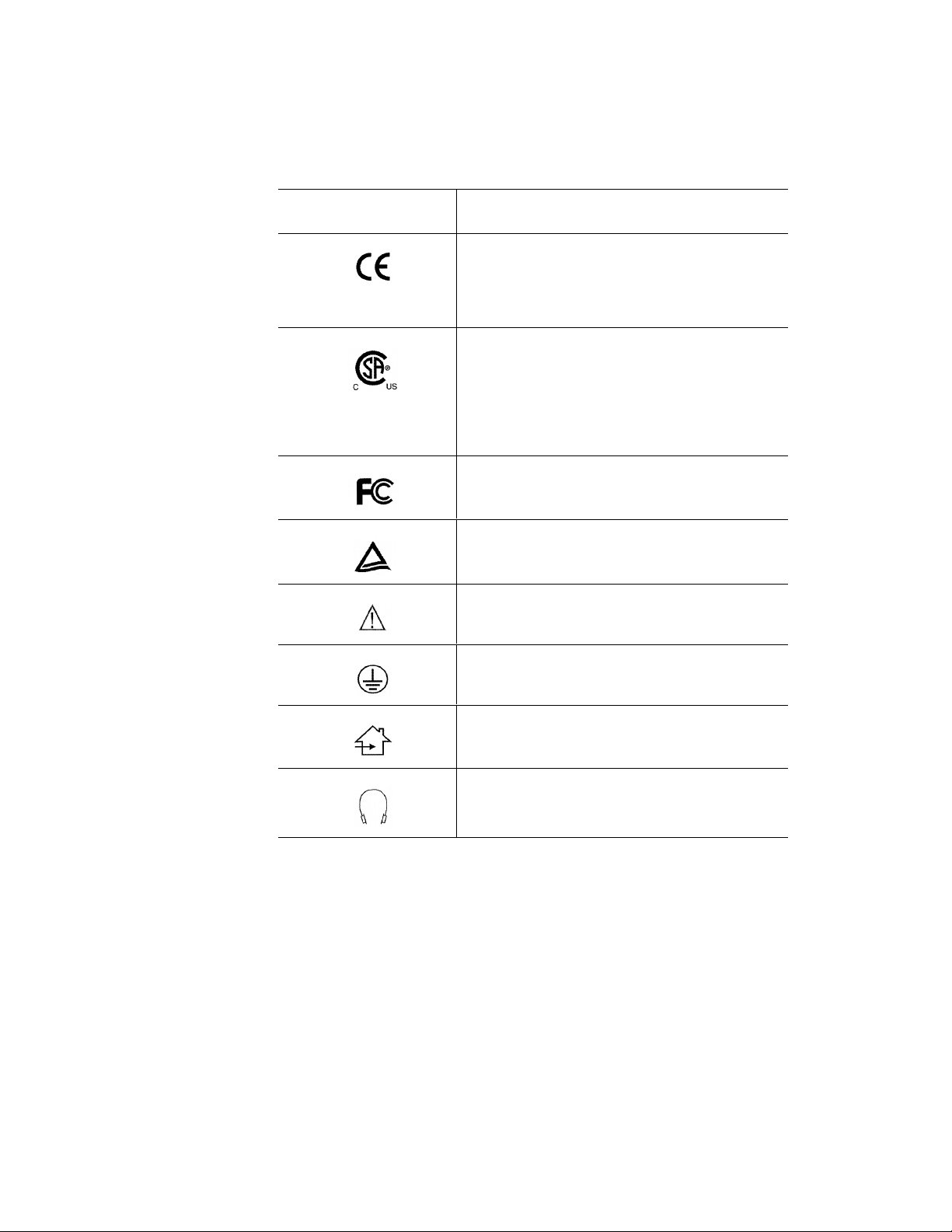
Symbol Explanations
This table explains the symbols appearing on the display or power
supply adapter.
This symbol… Indicates…
Proof of conformity to applicable European
Economic Community Council directives and
two harmonized standards published in the
official journa l of th e Euro pe an C om mun iti es .
The product has been tested and ce rt i fied by
CSA to C22. 2 No. 601.1-M1990. If this mark
appears with the indicators “C” and “US,” the
product is certified for the U.S. and Cana d ia n
markets, meeting the applicable U.S. and
Canadian stan dards.
The product has been tested to comply with
FCC Class B standards.
The product has been tested and ce rt i fied by
TÜV Rheinland in accor d ance with EN6061- 1.
More information available in accompanying
documents.
Protective earth ground.
Indoor use o nly.
Socket for headphones.
VSS15X / VSS15X-TR Operations Manual (020-0247-00 Rev. A)
Page 11

The VitalScreen S Display
The archi tecture of the VitalScreen S display incorporates an
active matrix liquid crystal display (AMLCD) panel that produces
a clear display with low radiation emission. This technology greatly
reduces the radiation-related health concerns associated with
cathode-ray tube (CRT) monitors.
More significant, the VitalScreen S display is medically certified
under UL 2601 and IEC 60601. These qualifications not only
make the display safer for the patient but also protect the
hospital from liability.
Your new VitalScreen S display is versatile, ergonomic, and userfriendly. It supports Plug and Play, and displays most standards
from 640 x 480 VGA to 1024 x 768 XGA. The digital controls
located on the front panel allow you to easily adjust the display
parameters using onscreen menus . Wh en i nc or p ora t e d into
a complete workstation, the display can be wall-mounted for
added conven ience.
Selecting a Workspace
Before you unpack the VitalScreen S display, select a suitable
workspace for the display and computer. You need a stable, level,
and clean sur fa c e near a wall ou tl et. E ven th ough this displa y
uses little power, pl ace it in a location that allows sufficient
airflow to ensure prope r ven ti l a t ion .
Avoid setting u p th e dis pl ay n ear a window where sun li gh t oft en
comes in. You wi l l ha v e diff i cu lt y s ee ing th e screen with glar e
reflecting off the display.
Unpacking the Display
Make sure the following items are included and are in
good condition. If any item is mi ssing or damage d, s ee
your dealer immediately.
• LCD screen
• Display-to-computer signal cable
• 1.5M stereo jack audio cable
• Touchscreen cable (VSS15X-TR only)
• CD with touchscreen driver and PDF of this manual
• Power supply
• EU Declaration of Conf or mit y
VSS15X / VSS 15X-TR Operations Manual (020-0247-00 Rev. A)
Page 12
2 | The VitalScreen S Display
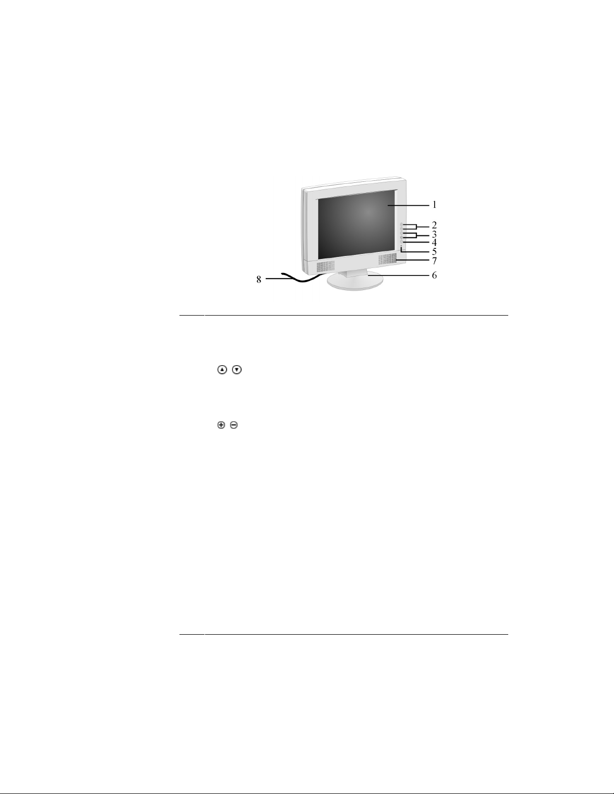
Identifying the Components
The VitalScreen S display pr ovi d es easy access to all con trols and
peripheral ports. The following illustrations of the front and back
panels identify the display controls and ports.
VitalScreen S Display Front Panel
1
LCD screen A 15-inch diagonal AMLCD.
The screen suppo r ts a maximum
resolution of 1024 x 768 (XGA).
2
3
4
5
6
Function UP and
DOWN buttons
Adjust PLUS and
MINUS buttons
Power ON/OFF Power switch.
Power ON Indi cator A light-emitting diode (LED) indicator
Desk stand Flat-surface support for the display.
Vertical arrows to navigate the
onscreen display horizontally.
UP selects the i co n to the right.
DOWN selects the icon to the left.
Controls to select the highlighted
submenu icon or to change the
value of the selected ico n.
that stays lit when the power is on and
the display is receiving a proper video
signal. The LED blinks slowly when
the displa y is in power-saving mode.
The stand allows you to pivot the
screen to various viewing angles.
7
Stereo speakers Two transmission channels for sound.
8
VGA input cable Display-to-computer signal cable.
VSS15X / VSS15X-TR Operations Manual (020-0247-00 Rev. A)
Page 13

The VitalScreen S Display | 3
VitalScreen S Display Back Panel
1
VGA connector A 1.5-meter cable with two 15-pin
D-Sub VGA connectors used to join
the display to the VGA card in your
computer.
2
Locking mini DIN
connector
Plug the power supply into this
connector.
3
Audio Line In (optional ) Connect you r PC to this jack to li s ten
to the computer audio through your
display stereo speakers. (You can
also connect the CD-ROM Line Out
to this jack.)
4
RS-232 Connector for
Optional Touch Screen
Link the RS-232 ca bl e to you r
computer’s RS-232 serial port
connector to use the optional touch
screen. This cable is provided with
the Optional Touch Screen package.
VSS15X / VSS 15X-TR Operations Manual (020-0247-00 Rev. A)
Page 14

4 | The VitalScreen S Display
Adjusting the Viewing Angl e
You can adjust your Vit a l Scr een S display to various vi ewin g
angles. This side view o f the dis pla y sh ows the angl e settin g
ranging from −5º to 25º.
VSS15X / VSS15X-TR Operations Manual (020-0247-00 Rev. A)
Page 15

Installing the Display
To install the VitalScreen S display, connect the power supply first.
Next, connect the VGA cable. Then choose whether to connect
optional st er eo s p ea k er s an d touch s c re en.
Connecting the AC Power
1
Plug the receptacle end of the AC power cord into the
AC power supply.
2
Plug the power connector of the power supply into the locking
mini DIN conn ec t or on the back panel of the Vi ta lS cr e e n S.
3
Insert the plug end of the power cord into a grounded wall
outlet. The plug on the powe r cab l e wil l va r y a c c or ding to the
electrical standard in your area.
Use a surge prot ect o r b et wee n th e pow e r su p pl y an d th e outlet
to prevent su dd en cu r rent variati ons fr om r eaching the dis play.
VSS15X / VSS 15X-TR Operations Manual (020-0247-00 Rev. A) 5
Page 16

6 | Installing the Display
Connecting the VGA Cable to the Computer
1 Turn off your comput er a nd the VitalScreen S disp la y b ef or e
connecting the display to the computer.
2
Connect the VGA signal cable to the D-sub VGA connect or on
the back panel the display.
3
Connect the oth er en d of the sign a l ca bl e t o the VGA p or t on
the computer.
4
Make sure the signal cable heads are properly aligned to
the VGA ports on your computer and display. Tighten the
connecting screws to ensure a secure connection.
5
Turn on your computer and display.
VSS15X / VSS15X-TR Operations Manual (020-0247-00 Rev. A)
Page 17

Installing the Display | 7
Connecting the Stereo Speakers (optional)
1 Connect the 1.5M sound cable to the Line Out on the audio card
in your computer.
2
Connect the oth er en d of the 1.5 M sou nd cable to the Lin e In
jack on the display.
3
Adjust the vol um e of th e s t er eo sp eakers by using th e s pea ke r
volume control function on the onscreen display.
Although th e dis play speakers ar e adequate for most au dio
applications, Planar does not recommend using the display
speakers a s th e
exclusive
audio source for medical alarms or
applications critical for audio performance.
VSS15X / VSS 15X-TR Operations Manual (020-0247-00 Rev. A)
Page 18

8 | Installing the Display
Connecting the Optional Touch Screen
Your VitalScreen S display has an optional touchscreen feature.
Link the RS232 connector on the display to the RS232 serial port
on your computer to enabl e th e touch screen.
1 Attach the one end of the RS232 cable provided with the
Optional Touch Screen package to the RS232 port on the
back panel of the display.
2
Attach the oth er end o f the cab l e to the RS232 serial port on
the b a ck of y our c omputer.
3 Load the touchscreen driver from the CD enclosed.
Power Management System
The VitalScreen S display com p li es wi th th e Video Electron ic
Standards Association DPMS (version 1.0p) power management
proposal. The VESA DPMS proposal provides four phases of
power-saving modes by detecting the horizontal or vertical
sync signal.
When the display is in power-saving mode or detects an
incorrect timing, the display screen goes blank and the
power LED indi cat o r b li nks.
VSS15X / VSS15X-TR Operations Manual (020-0247-00 Rev. A)
Page 19

The Display Controls
Read this chapter carefully to use your VitalScreen S display
efficiently and effectively.
Adjusting the Display
Using th e onscreen di splay, y ou can adjust the contrast,
brightn ess, display position, disp lay cl a ri t y, a nd col o r
temperature. You can also adjust the stereo speaker
volume and set the onscreen display parameters.
Using the Onscreen Display Main Menu
The VitalScreen S displa y feat u r es a n intuitive, men u -driven,
onscreen display. You can access the onscreen display, or OSD,
when the display is powered-up. If your computer is in powersaving mode, or is p owered-down, the onscreen display is
inaccessible.
Use the Functi on and A d jus t b utt on s (shown on the
left) to navigate the OSD main menu. To activate the
menu, press the UP button (
menu, use the DOWN button (
main menu choices. The selected option is highlighted
in yellow. Each main menu has submenu associated
with it.
This screen appears when you access the OSD main menu. The
top icons repr esent the seven m ain menus. Bel ow th ese are icons
for the submenus, then a description of the selected menu.
). To navigate the main
) to scroll between the
VSS15X / VSS 15X-TR Operations Manual (020-0247-00 Rev. A) 9
Page 20

10 | The Displ ay Controls
The following tables describe the main menus a nd submenus.
The Seven Main Menus
Auto Adj us t
and select the sett ings tha t ar e appropriate
for your system requirements. This function
tunes the di splay to the video card in your
computer.
Monitor-Control
display characteristics such as the
horizontal or vertical position, display
phase, display clock, and factory reset.
Adjusting thes e sett in gs is nec es sary if
the results from the Auto Adjust function
are not satisfactory.
OSD-Control
and setting of the onscreen display.
. Lets the displa y determine
. Lets you adjust the
. Lets you adjust the position
MISC-Control
text language of the onscreen display,
adjust the display speaker volume, and
show/display the current v ideo information
being sent to the display from the video
card.
. Lets yo u se l e ct the desir e d
Graphic-Control. Lets you adjust the
display contrast, brig ht n es s, shar pne s s
and color settin g s.
Graph/Text
resolution form 640 x 400 to 720 x 400
pixels. This function has no effect with
graphic operati ng s ystems su ch as
Microsoft
Exit
. Closes the onscreen display.
. Lets you switch DOS text
®
Windows®.
VSS15X / VSS15X-TR Operations Manual (020-0247-00 Rev. A)
Page 21

The Display Contr ols | 11
Auto Adj us t
Pressing the Adjust PLUS button ( )
activates the Auto Adjust procedure
while the Auto Adjust main menu is
selected. The procedure takes about
2 seco nds. On ce fini shed, the OSD
menu disappears after a sh ort timeout period.
Monitor–Control
H-Position. Press the Adjust PLUS or MINUS button ( / ) to move
the display image horizo ntal l y to the desired position.
V-Position. Press the Adjust PLUS or MINUS button ( / ) to move
the display image vertically to the desired position.
Phase. Press the Adjust PLUS or MINUS button ( / ) to fine-tune
the displayed image. An impr oper phase adjustment results in pixel
jitter or display noise.
Clock. Press the Adjust PLUS or MINUS button ( / ) to stabilize
the display clock timing. An improper clock setting results in wide
vertical bands on the display.
Pressing the Adjust PLUS button ( )
activates the Monitor-Control submenu. Use the Function UP and
DOWN buttons (
between the submenu items. Use
this menu item only if the results of
the Auto Adjust function are
unsatisfactory.
/ ) to scroll
Reset. Press the Adjust PLUS button ( ) to reset the Monitor-Control
submenu values to the factory default values.
Exit. Press the Adjust PLUS button ( ) to exit t he M onitor-Control
submenu.
VSS15X / VSS 15X-TR Operations Manual (020-0247-00 Rev. A)
Page 22

12 | The Displ ay Controls
OSD–Control
Pressing the Adjust PLUS button ( )
activates the OSD-Control submenu.
Use the Function UP and DOWN
buttons (
the submenu items.
/ ) to scroll between
OSD-H-Position. Press the Adjust PLUS or MINUS button ( / )
to move the OSD menu horizontally.
OSD-V-Position. Press the Adjust PLUS or MINUS button ( / )
to move the OSD menu vertically.
Exit. Press the Adjust PLUS button ( ) to exit the OSD-Co ntrol
submenu.
MISC–Control
Language. Press the Adjust PLUS or MINUS button ( / ) to select
the desired OSD display language. Lan guages supported: English,
German, French, Spanish, and Italian.
Pressing the Adjust PLUS button ( )
activates the MISC-Control submenu.
Use the Function UP and DOWN
buttons (
submenu items.
/ ) to scroll between the
Audio Vol ume. Press the Adjust PLUS or MINUS button ( / )
to decrease or increase the v olume of the stereo speakers.
Information. The Information submenu displays the current
resolution, vertical refresh rate, and display fir m ware version.
Exit. Press the Adjust PLUS button ( ) exit the MISC-Control
submenu.
VSS15X / VSS15X-TR Operations Manual (020-0247-00 Rev. A)
Page 23

The Display Contr ols | 13
Graphic–Control
Pressing the Adjust PLUS button ( )
activates the Graphic-Control submenu. Use the Function UP and
DOWN buttons (
between the submenu items.
Contrast. Press the Adjust PLUS or MINUS button ( / ) to adjust
the difference between the lightest and darkest areas of the di splay.
The contrast level can range from 0 to 63.
Brightness. Press the Adjust PLUS or MINUS button ( / ) to
adjust the intensity of the display backlight.
Sharpness. Press the Adjust PLUS or MINUS button ( / ) to
select the desired sharpness setting.
Color. Press the Adjust PLUS or MINUS button ( / ) to sele ct the
desired color temperat ure setting. The available options are CIE
coordinate values 9300°, 6500°. Selecting the USER option allows
you to customize the Red, Green, and Blue color coordinates.
. Press the Adjust PLUS or MINUS button (
R, G, B
individual adjustments to the Red, Green, and Blue coordinates
for the customized color temperature. There are 127 levels of
adjustments (0 (zero) to 127) avai lable.
Before adjusting these fields, select the User option in the
Color submenu.
) to scroll
/
/ ) to make
Exit. Press the Adjust PLUS or MINUS button ( / ) to exit
the Graphic-Control submenu.
VSS15X / VSS 15X-TR Operations Manual (020-0247-00 Rev. A)
Page 24

14 | The Displ ay Controls
Graph/Text
Pressing the Adjust PLUS button ( )
toggles the DOS resolution between
640 x 400 and 720 x 400.
Exit
Pressing the Adjust PLUS button ( )
exits the OSD menu. The OSD menu
also exits after a brief time-out period.
VSS15X / VSS15X-TR Operations Manual (020-0247-00 Rev. A)
Page 25

Technical Information
VSS15X / VSS15X–TR Display Specification
LCD Panel 15-inch XGA
Control Function s Power Software Power switch with LED indicator
Onscreen Display (OSD)
Display Area (mm) 304.1 x 228.1 (15-inch diagonal)
Response Time (ms)
(Rise+Fall)
Contrast Ratio 500:1 typical
Brightness 300 cd/m2 typical (non-touch)
Viewing Angle (degrees) Ho rizontal: 70/70 (L / R ) ; V e r ti c a l : 6 5 /55 (U/D )
Pixel Pitch (mm) 0.297 x 0.297
Display Colors 15.4 M, 8 bit
Video Interface VGA Compatible Analog RGB/ Composite Sync
Scanning Frequency
H/V, Hz
Number of Factory
Preset Mode
Power Management Meets VESA DPMS
Power Consumption
(ON/OFF, W)
Dimensions W x H x D (mm) 408 x 388 x 175
Net Weight (kg) 6.9
Power Supply 12V/3A
Options Wall-mount, desk stand, touch screen
Environment Operating Temperature: 0 (zero) to 40° C
Audio (Two 1 (one) Watt
speakers with amplifier)
Regulatory See “Regulatory C ompliance” on page iii
(Press to turn OFF, over 1 (one) sec. to turn ON)
Main Menu Submenu
Auto Adjust
Monitor Control
OSD Control
Misc. Control
Graphic Control
Graph/Text
OSD Exit
25 ms typical
2
225 cd/ m
24-62K
50-75
22
40/4.5 Max imum.
Relative Humidity: 10% to 90%
Yes
typical (resistive touch)
Horizontal Position/Vertical
Position/Phase/Clock/Reset/Exit
OSD Horizontal Position/OSD Vertical Position/Exit
Language/Audio Volume/Information/Exit
Contrast/Brightness/Sharpness/Color/RGB/Exit
640 x 400/720 x 400
VSS15X / VSS 15X-TR Operations Manual (020-0247-00 Rev. A) 15
Page 26

Supported Timing
Item
Standard
1 NEC PC98 640x400 25.20 70.15 31.50
2 NEC PC98 640x400 21.05 56.42 24.83
3 MAC 13-inch mode 640x480 30.24 66.67 35.00
4 MAC 16-inch mode 832x624 57.28 74.55 49.73
5 MAC 17-inch mode 1024x768 80.00 75.02 60.24
6 VGA 640x350 25.18 70.09 31.47
7 VGA 640x400 25.18 70.09 31.47
8 VGA 640x480 25.18 59.94 31.47
9 VESA 640x480 31.50 72.81 37.86
10 VESA 640x480 31.50 75.00 37.50
11 VESA 800x600 36.00 56.25 35.16
Resolution
Dot Clock
(MHz)
Vertical
Scanning
Frequency
(Hz)
Horizontal
Scanning
Frequency
(kHz)
12 SVGA 800x600 40.00 60.32 37.88
13 VESA 800x600 50.00 72.19 48.08
14 VESA 800x600 49.50 75.00 46.88
15 VGA 720x400 28.32 70.09 31.47
16 XGA 1024x768 65.00 60.00 48.36
17 VESA 1024x768 75.00 70.07 56.48
18 VESA 1024x768 78.75 75.03 60.02
19 1024x768 71.64 66.13 53.96
20 SUN 1024x768 64.13 59.98 48.29
21 SUN 1024x768 74.25 70.04 56.59
22 SUN 1024x768 84.38 77.07 62.04
16 VSS15X / VSS15X-TR Operations Manual (020-0247-00 Rev. A)
Page 27

Troubleshooting
The VitalScreen S display is pre -a d jus t ed with standard VG A
timing. Output timing differences among various VGA cards may
initially cause an unstable or unclear display when a new display
mode or new VGA ca rd i s sele ct ed.
The VitalScreen S display supports multiple VGA modes.
See Appendix B for a listing of the factory modes supported
by this display.
PROBLEM: Display unclear and unst able.
To stabilize and clarify your display, follow these steps:
1
Apply the Auto Adjust opti on in th e OSD m enu f or th e display
to adjust automatically to the video signal.
2
If the image re ma i ns unstable, a d ju s t the dis p l ay on a screen
showing vertical lines. In Windows, load a wallpaper bitmap
that has vertical lines on it (or select the Windows shutdown
screen).
3
After you load the wallpaper, open the OSD and select the
Clock function. Press the Adjust PLUS (or MINUS) button and
continue to press the button until you see vertical dark and
light bands across the screen.
4
When you see distinct light and dark vertical bands, release
that Adjust button and press the opposite Adjust button.
The vertical dark and light bands will decrease in number.
Continue to press the button until the distinct bands
disappear and you see a clear display.
5
Press the Function button to select the Phase function. This
function adjusts the horizontal display. Press the Adjust PLUS
(or MINUS) button. Horizontal dark and light lines appear.
The numbe r o f lin es increases a s you p r ess the button. Pres s
the Adjust MINUS (or PLUS) butt on unti l th e lines di sapp ea r
and you see a clear display.
VSS15X / VSS 15X-TR Operations Manual (020-0247-00 Rev. A) 17
Page 28

18 | Troubleshooting
PROBLEM: No image on LCD screen.
If there is no image on the LCD screen, follow these steps :
1
2
3
Make sure that the power ind ic at or in the displ ay is lit, that
all connections are secure, and that the system is running to
the correct timing. See Appendix B for information on timing.
Turn off the Vita lSc reen S display and then turn it on again.
Press the Function UP button once and press either the
plus or minus Adjust PLUS (or MINUS) button several times.
If there is still no dis p la y, press the other Ad ju st b utt on
several times.
If step 2 doesn’t solve the problem, connect your computer
to another ex t erna l C R T m onitor. If the computer opera t es
properly with a CRT monitor but does not work with the
VitalScreen S display, and the power LED is blinking on the
display, the output timing of the VGA card you in stalled may
be out of synchr on ou s r a ng e assigned for the Vi tal Sc r e en S
display. Change to an alternate mode (listed in Appendix B)
or replace the VGA card and repeat steps 1 and 2.
4
If your computer doesn’t work with the CRT monitor, check
the BIOS for a dual scan setting under the display mode item.
Set the BIOS display mode to Dual Scan or CRT and try again.
If there is still no image, there may be a problem with your
system. Get help from technical support.
5 If the power LED is not lit, chec k t o see if th e AC p ow er
connector is securely connected. Verify that the AC adapter
LED is lit. If it is not, consult your Planar dealer for assistance.
VSS15X / VSS15X-TR Operations Manual (020-0247-00 Rev. A)
Page 29

Index
A
AC power, connecting, 5
Adjust button, 2, 9
adjusting viewing angle, 4
audio li ne, 3
Auto Adjust menu, 10, 11
C
cleaning instructions, ix
components, identifying, 2
connecting
AC power, 5
stereo speakers, 7
touch screen, 8
VGA cable, 6
D
desk stand, 2
display
adjusting, 9
back panel, 3
cleaning, ix
controls, 9
front panel, 2
installing, 5
troubleshooting, 17
unpacking, 1
DPMS. See power, management system
M
menu
Exit, 10, 14
Graphic-Control, 10, 13
Graph/Text, 10, 14
main, onscreen display, 9, 10
MISC-Control, 10, 12
Monitor-Control, 10, 11
OSD-Control, 10, 12
O
onscreen display main menu, 9
ordering , 23
OSD-Control menu, 10, 12
P
power
indicator, 2
management sy s tem , 8
switch, 2
RS232 connector, 3
S
safety instruction s, viii
selecting workspace, 1
stereo speakers, 2, 7
supported timing, 16
E
Exit menu, 10, 14
F
Function button, 2, 9
G
Graphic-Control menu, 10, 13
Graph/Text menu , 10, 14
I
information
ordering, 23
technical, 15
installing display, 5
L
LCD screen, 2, 18
T
technical information, 15
timing, supported, 16
touch screen
cleaning, ix
connecting, 8
troubleshooting, 17, 18
U
unpacking display, 1
V
VGA
cable, connecting, 6
connector, 3
input cable, 2
viewing angle, adjusting, 4
W
warranty, 21
workspace, selecting, 1
VSS15X / VSS 15X-TR Operations Manual (020-0247-00 Rev. A) 19
Page 30

Page 31

Description of Warranty
Planar Systems, Inc. (Planar) warrants that the goods sold hereunder
will be free of defects in materials and workmanship, and such goods
will substantially conform to the specifications furnished by Planar,
and to any drawings or specif ications furnis hed to Planar by the Buyer
if approved by Planar. This wa rranty shall be effectiv e only if Planar
receives notice of such defect or nonconformance during the period of
the warranty . Sole and exclusive liabi lity of Planar for breach of
warranty shall be, at the company’s option, to repair or replace the
Planar product(s) with refurbished units or provide a credit to Buyer
in the amount of the purchase price.
Commencement and Duration of War ranty
The warranty period begins on the date of shipment from Planar.
The goods sold hereunder are warranted for a period of 36 months
from date of shipme nt unless ot herwise agr eed to b y Buy er and
Planar. No extension of the warranty will be given during the time
the goods are in the possession of Planar.
Place of Repair or Replacement
To obtain service under this warranty, Buyer must notify Planar of the
defect before expiration of the warranty period and request a “Return
Material Authorization Number (RMA).” If the configuration has been
modified in any manner, the product must be returned to its original
configurat ion before any warranty service will be per f ormed by Plana r.
No goods are to be returned to Planar without prior authorization.
Buyer will be responsible for packaging and shipping the defective
goods to the appropriate Planar Service Facility. For North America,
the service facility is located in Espoo, Finland.
Limitation of Warranty
The for e going warra n ty shall not apply to defects result i n g f r om
(a) improper or inadequate maintenance by Buyer; (b) unauthorized
modification of the goods; (c) operations of the goods outside the
environmental specifications of the goods; (d) neglect, misuse, or
abuse of the goods; or (e) modificati on or integra tion with other
goods not covered by the Planar warranty when such modification
or integration increases the likelihood of damage to the goods.
THE WARRANTY IS GIVEN BY Planar IN LIEU OF ANY OTHER
WARRANTIES, EXPRESS OR IMPL IED. Planar DISCLAIMS ANY
IMPLIED WARRANTIES OF MERCHANTABILITY OR FITNESS
FOR A PARTICULAR PURPO SE. ITS RE SPON SI B ILI T Y TO
REPAIR OR REPLACE DEFECTIV E PRODUCTS IS THE SOLE
AND EXCLUSIVE REM E DY PRO VID ED TO THE BUY ER FO R
BREACH OF THIS WARRANTY. Planar WILL NOT BE LIABLE
FOR ANY INDIRECT, SPECIAL, I NCIDENTAL, OR CONSEQUENTIAL
DAMAGES IRRESPECTIVE OF WHETHER Planar HAS ADVANCE
NOTICE OF THE POSSIBILITY OF SUCH DAMAGES.
VSS15X / VSS 15X-TR Operations Manual (020-0247-00 Rev. A) 21
Page 32

The warranty set forth above shall not be enlarged, diminished, or
affected by, and no obligation or liability shall arise from Planar, any
authorized dealer, or any other person’s r endering of technical advice,
assistance, or ser vices in connection wit h the Bu yer’s order of the goods
furnished hereunder. The Buyer is not relying on skill or judgment of
Planar to select or furnish suitable goods.
Installation
Planar makes no warranty with respect to any installation of Planar
product(s) by Planar, any au thorized dealer, or any other person.
Technical Assistan ce
In North America, call (503) 748-1100 between 8 A.M. and 5 P.M. Pacific
time, Monday through Friday, or send a description of your technical
issues and e-mai l address to app_eng@planar.com.
In Europe, call +358 9 420 01 between 8
A.M. and 4 P.M. Finnish time
(Eastern European time), Monday through Friday, or send a description
of your technical issues and e-mail address to tech_support@planar.com.
Repair Service
In North America, call Planar at (503) 748-1100 between 8 A.M. and
4
P.M. Pacific time, Monday through Friday, or fax your request to
(503) 748-1493. You will need the unit’s serial number and a brief
description of the problem to receive an RMA number.
In Europe, call Planar Customer Service at + 358 9 420 01 between 8
and 4
P.M. Eastern European time, Monday through Friday, or fax your
request to +358 9 420 0200. You will need the unit’s serial number and
a brief description of the problem to receive an RMA number.
To protect Planar employees from potential health hazards, Plan ar
requires that the RMA product b e disinfected before returning to
Planar for service. Any product not cleaned prior to shipment will
be returned to the customer.
Returns are not accepted without an assigned RMA number.
In-transit damage is not covered by the warranty. Insure your shipment.
Planar will only pay for the return shipment by surface transportation.
It is responsibility of the sender to prepay transportation charges.
A.M.
22 VSS15X / VSS15X-TR Operations Manual (020-0247-00 Rev. A)
Page 33

Ordering Information
VSS15X (Non-Touch) Display Part Number
VSS 15X 15-inch XGA VitalScreen S
Medically Certified Display with desk stand
and US power cord
VSS 15X 15-inch XGA VitalScreen S
Medically Certified Display with desk stand
and European power cord
VSS 15X 15-inch XGA VitalScreen S
Medically Certified Display with mounting
plate and US power cord
VSS 15X 15-inch XGA VitalScreen S
Medically Certified Display with mounting
plate and European power cord
VSS15X-TR (Resistive-Touch) Display Part Number
VSS 15X-TR 15-inch XGA VitalScreen S
Medically Certified Display with desk stand
and US power cord
VSS 15X-TR 15-inch XGA VitalScreen S
Medically Certified Display with desk stand
and European power cord
997-2261-00
997-2262-00
997-2265-00
997-2266-00
997-2401-00
997-2402-00
VSS 15X-TR 15-inch XGA VitalScreen S
Medically Certified Display with mounting
plate and US power cord
VSS 15X-TR 15-inch XGA VitalScreen S
Medically Certified Display with mounting
plate and European power cord
997-2403-00
997-2404-00
VSS15X / VSS 15X-TR Operations Manual (020-0247-00 Rev. A) 23
Page 34

VSS15X (Non-Touch) Cables Original Part Replacement Part
US power cord 903-0169-00
European power cord 903-0251-00
VGA cable 903-0454-00 903-0167-00
Audio cable 903-0455-00 903-0168-00
VSS15X-TR (Resistive-Touch) Cables Original Part Replacement Part
US power cord 903-0169-00
European power cord 903-0251-00
VGA cable 903-0454-00 903-0167-00
Audio cable 903-0455-00 903-0168-00
Touch cable 903-0456-00 903-0233-00
24
VSS15X / VSS15X-TR Operations Manual (020-0247-00 Rev. A)
Page 35

Page 36

North and South America Sales Europe and Asia-Pacific Sales
Planar Systems, Inc.
1400 NW Compton Drive
Beaverton, OR 97006-1992
+1 (50 3) 748-1100 phone
+1 (503) 748-1493 fax
sales@planar.com
app_eng@planar.com
Planar Systems, Inc.
Olarinluoma 9, P.O. Box 46
FIN-02201 Espoo, Finland
+358 9 420 01 phone
+358 9 420 0200 fax
intlsales@planar.com
tech_support@planar.com
 Loading...