

Page 1
OPERATIONS MANUAL
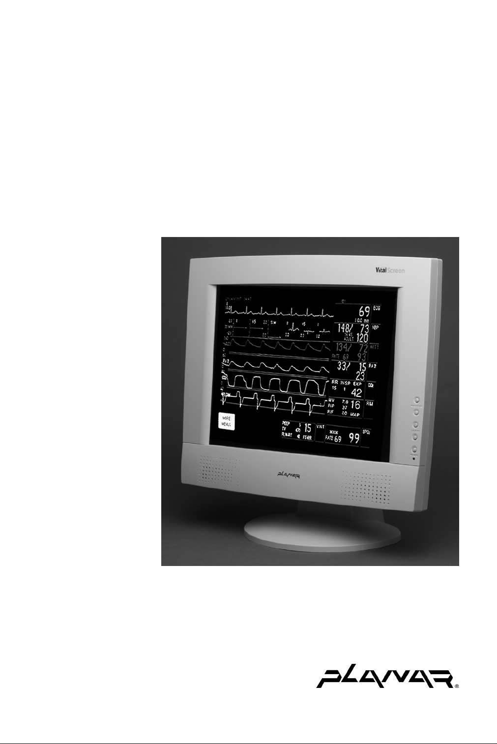
VitalScreen™ S
15" Medically Certified Display
VSS15X / VSS15X-TR
QUICK LINKS
Contents
Index
About the Display
Display Installation
Display Controls
Troubleshooting
Ordering Parts
Warranty
Page 2

Americas Sales
Planar Systems, Inc.
1195 NW Compton Drive
Beaverton, OR 97006-1992 USA
(503) 748-1100 phone
(503) 748-1493 fax
Medical Sales
Planar Systems, Inc.
400 Fifth Avenue
Waltham, MA 02451-8738 USA
(781) 895-1155 phone
(781) 895-1133 fax
Europe & Asia-Pacific Sales
Planar Systems, Inc.
Olarinluoma 9, P. O. Box 46
FIN-02201 Espoo, Finland
+ 358 9 420 01 phone
+ 358 9 420 0200 fax
Internet address for sales information: medicalsales@planar.com
Internet address for technical support: medicalsupport@planar.com
World Wide Web site: www.planar.com
Planar Systems, Inc. © 2003. All rights reserved.
Information in this document has been carefully checked for accuracy; however, no
guarantee is given to the correctness of the contents. This document is subject to
change without notice. Planar provides this information as reference only. Reference
to other vendors’ product does not imply any recommendation or endorsement.
This document contains proprietary information protected by copyright. No
part of this manual may be reproduced by any mechanical, electronic, or other
means, in any form, without prior written permission of the manufacturer.
Planar is a registered trademark and VitalScreen is a trademark of Planar Systems, Inc.
DOCUMENT HISTORY
Date Description
September 2002 020-0247-00 Rev. A
August 2003 020-0247-00 Rev. B
October 2003 020-0247-01 Rev. A
Page 3

iii
Contents
Regulatory
About
Product
About the VitalScreen S
1
Selecting a Workspace . . . . . . . . . . . . . . . . . . . . . . . . . . . . . . . . . 1
Unpacking the Display . . . . . . . . . . . . . . . . . . . . . . . . . . . . . . . . . 1
Identifying the Components . . . . . . . . . . . . . . . . . . . . . . . . . . . . 2
Adjusting the Viewing Angle . . . . . . . . . . . . . . . . . . . . . . . . . . . . 4
Installing the Display
2
Connecting the AC Power . . . . . . . . . . . . . . . . . . . . . . . . . . . . . . 5
Connecting the Video Cable . . . . . . . . . . . . . . . . . . . . . . . . . . . . . 6
Connecting the Stereo Speakers . . . . . . . . . . . . . . . . . . . . . . . . . . 7
Connecting the Optional Touch Screen . . . . . . . . . . . . . . . . . . . . . 8
Power Management System . . . . . . . . . . . . . . . . . . . . . . . . . . . . . 8
3
Display Controls
Compliance
This
Manual
Information
. . . . . . . . . . . . . . . . . . . . . . . . . . . . . iv
. . . . . . . . . . . . . . . . . . . . . . . . . . . . . . . . . v
. . . . . . . . . . . . . . . . . . . . . . . . . . . . . . . vi
. . . . . . . . . . . . . . . . . . . . . . . . . . . . 1
. . . . . . . . . . . . . . . . . . . . . . . . . . . . . . . 5
. . . . . . . . . . . . . . . . . . . . . . . . . . . . . . . . . . . 9
Hot Key Functions . . . . . . . . . . . . . . . . . . . . . . . . . . . . . . . . . . . 10
Onscreen Display Main Menu . . . . . . . . . . . . . . . . . . . . . . . . . . . 10
Function Menus . . . . . . . . . . . . . . . . . . . . . . . . . . . . . . . . . . . . . 11
Appendix A: Technical Information
Appendix B: Supported Timing
Appendix C: Troubleshooting
Index
. . . . . . . . . . . . . . . . . . . . . . . . . . . . . . . . . . . . . . . . . . . . 21
. . . . . . . . . . . . . . . . . . 17
. . . . . . . . . . . . . . . . . . . . . . 18
. . . . . . . . . . . . . . . . . . . . . . . 19
Page 4

iv
Regulatory Compliance
This display has been tested and certified to international medical safety
standards IEC/EN 60601-1 and IEC/EN 60601-1-2, and is certified to meet
C22.2 No. 601.1-M1990 (C US Mark).
Because many medical offices are located in residential areas, the medical display,
in addition to meeting medical requirements, has also been tested and found to
comply with the limits for Federal Communications Commission (FCC) Class B
computing devices in a typically configured system. It is the system integrator or
configurer’s responsibility to test and ensure that the entire system complies with
applicable electromagnetic compatibility (EMC) laws.
Planar Systems, Inc. has made great efforts to support the medical device industry,
in particular, medical device manufacturers and medical device system integrators.
We offer state-of-the-art color displays that are compliant with worldwide accepted
medical device safety standards, and for the European market, CE-marked displays
based on compliance with counsel directive 93/42/EEC commonly referred to as the
Medical Device Directive (MDD). The following summarizes our qualification of these
displays as it relates to compliance with the MDD.
The European Medical Device Directive requires that the intended use of the device
be defined. The intended use of these displays is “to display alphanumeric, graphic,
and image data as inputted from any type of medical device.” These displays do not
provide a measurement function in any way, and it is the device and systems
manufacturer’s responsibility to verify its function in the integrated device or system.
The display was classified as required by the MDD according to Annex IX of the
directive and the medical device (MEDDEV) guidance available at the time of
classification. Because the display uses electrical energy and has no direct patient
connections and—by itself—no medical utility, the display is classified according to
Rule 12 as an MDD Class I device-component or accessory. The MDD states that
manufacturers of Class I medical devices or accessories shall satisfy the requirements
in regard to design and manufacturing controls, that is, the applicable assessment
route to be used for CE-marking under the MDD, and it shall carry the CE mark
according to Annex XII of the directive, with no notified body annotation.
The applicable safety standards for an MDD Class I display are IEC/EN 60601-1:1997
along with Amendments 1 and 2. To help the medical device designer evaluate the
suitability of these displays, Planar has also conducted EMC testing to IEC 60601-1-2
as it can be applied. The display with its power supply alone does not represent a
functional medical device. Hence, Planar configured a minimal operating system to
exercise the display. The resulting data are made available to interested parties.
The data are informative data, not certification data. Certification data must be
obtained by the device or system integrator according to Article 12 of the MDD titled
“Particular procedure for systems and procedure packs.” Paragraph 2 clearly outlines
the device or system integrator’s responsibility in this matter.
In summary, Planar Systems, Inc. is CE-marking these displays under the Medical
Device Directive, which establishes compliance to the basic medical safety standards.
However, EMC compliance can only be accomplished in the configured medical
device or system and is the responsibility of the device or system manufacturer.
Planar has the necessary documentation such as IEC 60601-1 notified body and
other third-party test reports and certifications, a risk/hazard analysis, an essential
requirements checklist, and the Planar International Electrotechnical Commission
(IEC) declaration of conformity.
Page 5

v
Planar Systems, Inc., located in Beaverton, Oregon, USA, is the manufacturer of these
displays in the meaning of the directive. As required by the MDD in Article 14, Planar
Systems, Inc., not residing in the European Economic Area (EEA), has a European
representative, Planar Systems, Inc.—Espoo, Finland.
In the opinion of Planar Systems, Inc. registration required to put this device into
commerce is the responsibility of the medical device/system manufacturer, and
Planar supports this requirement by providing a European commission (EC)
declaration of conformity. If Planar supplies a display to an end user, rather than
a device manufacturer, it is the end user’s responsibility to ensure continued
compliance with the MDD of the system in which the display is integrated.
For vigilance reporting as required under Article 10 of the MDD, Planar Systems, Inc.
will provide any information requested by competent authority to support any
reported incident investigation by such an authority.
European Union Declaration of Conformity for Medical Applications
A Declaration of Conformity has been filed for this product. For additional copies of
the Declaration of Conformity document, contact Planar Systems, Inc. and request
document number 001-0014-07 “Declaration of Conformity.”
About This Manual
This manual contains information on the setup, use, and proper
maintenance of VitalScreen
S 15" display models VSS15X (non-touch)
™
and VSS15X-TR (resistive touch). Keep this manual for future reference.
The section on product information provides safety and cleaning
instructions. It also explains the symbols used on the products.
Chapter 1 provides an overview of the VitalScreen S display. It lists the
contents of the display package and identifies the components of the
display. Chapter 2 explains how to install the display correctly and use
optional components. Chapter 3 explains the menus and function
controls built into the display.
Appendix A shows technical information. Appendix B gives supported
timing. Appendix C offers troubleshooting solutions.
Description of warranty and ordering information are provided at
the back of this manual.
Page 6

vi
Product Information
•
•
•
•
•
•
•
•
•
•
•
Safety
instructions
Store the display in its original shipping carton when it is not in
operation for extended periods of time. Also use the original packing
materials and carton when shipping the display.
Do not place the display near a window. Exposing the display to rain,
water, moisture, or direct sunlight can damage it.
Do not place anything on top of the video cable. Make sure
the cable is placed where it will not be stepped on.
Do not apply excessive pressure to the screen. Excessive
pressure may cause permanent damage to the display.
Refer all servicing to qualified personnel to maintain your
warranty. The display and power adapter units contain no
user-serviceable parts.
Do not cover or obstruct the venting holes on the back of
the display.
Store the display in an environment with a temperature range
from -20 to 65 degrees Celsius. Storing your display outside that
temperature range could result in permanent damage.
Do not expose the display to liquid or drop it. If the case has been
damaged, the unit may pose a shock or fire hazard. Unplug the unit
immediately and call customer service for assistance.
Replace any cord or cable that is frayed or damaged with another
of the same type and rating, as supplied by Planar. The safety and
regulatory listings and certifications are based on the cable supplied
by Planar.
Use only the power adapter that has been tested and approved for
use with this display product. The power adapter must be plugged
into a grounded power outlet.
Do not immerse the power adapter in liquid, or a safety hazard could
arise during use.
Do not use the power adapter near inflammable anesthetics.
Page 7

1
2
3
4
•
•
•
•
•
•
vii
Cleaning
instructions
Use only the products listed below for cleaning the display. The
products differ for cleaning the screen and cleaning the plastic
enclosure. Be sure you use only the specific products approved for
either the screen or the enclosure.
Always apply the product to a clean nonabrasive cloth and then wipe
the screen or plastic enclosure. Cleaners applied directly to the display
could leak inside a non-sealed unit and cause damage. Be careful not to
splash solvents on the screen or enclosure.
Recommended cleaning solution for screen
Use 70 percent isopropyl alcohol. This is the only cleaning solution
approved for use on the non-touch screen (model VSS15X) and the
touch screen (model VSS15X-TR).
Do NOT use water or solvents (such as ketone, acetone) and aromatics
(such as xylene, toluene).
To clean the screen
Switch the power off.
Dampen a clean nonabrasive cloth with 70 percent
isopropyl alcohol.
Wipe the screen gently with the dampened cloth.
Dry the screen with a clean nonabrasive cloth to remove
any residue.
Recommended cleaning solutions for plastic enclosure
You may also use 70 percent isopropyl alcohol to clean the plastic
enclosure. Otherwise, use only these approved products to clean
the enclosure.
Cidex®
Clorox Clean-Up®
“Green soap” United States Pharmacopoeia (USP)
Formula 409®
Sani-Cloth® Plus
Virustat TBQ™
Do NOT use these products on the screen.
Page 8
viii
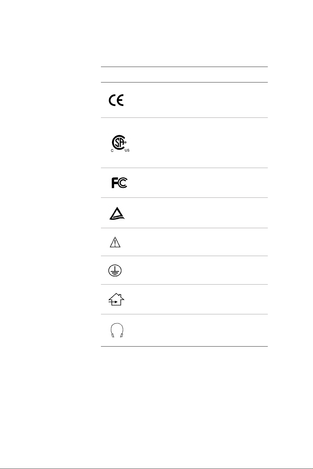
Symbol
explanations
This table explains the symbols appearing on the display or
power adapter.
Symbol Description
Proof of conformity to applicable European
Economic Community Council directives and
two harmonized standards published in the
official journal of the European Communities.
The product has been tested and certified by
CSA to C22.2 No. 601.1-M90. If this mark appears
with the indicators "C" and "US," the product
is certified for the Canadian and U.S. markets,
meeting the applicable Canadian and
U.S. standards.
The product has been tested to comply with
FCC Class B standards.
The product has been tested and certified by
TÜV Rheinland in accordance with EN6061-1.
More information available in
accompanying documents.
Protective earth ground.
Indoor use only.
Socket for headphones.
Page 9

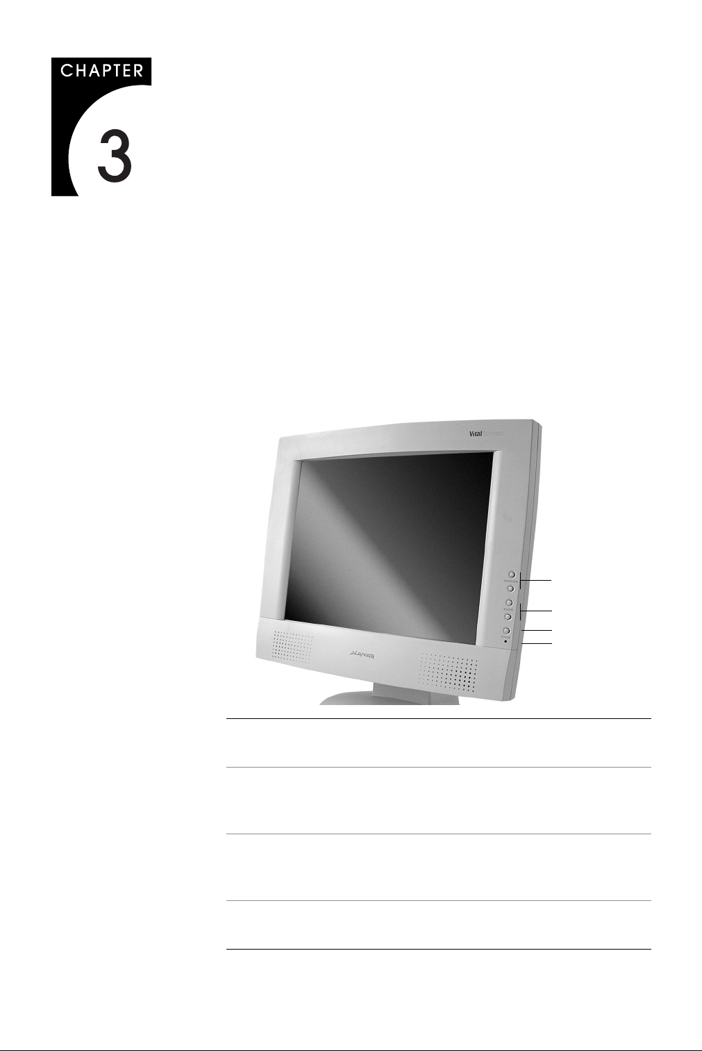
About the VitalScreen S
•
•
•
•
•
•
•
•
•
The architecture of the VitalScreen
panel that produces a clear display with low radiation emission. This
technology greatly reduces the radiation-related health concerns
associated with CRT monitors.
More significant, the VitalScreen S display is medically certified under
UL 2601 and IEC 60601. These qualifications make the display safer for
the patient and protect the hospital from liability.
Your new VitalScreen S display is versatile, ergonomic, and userfriendly. It supports Plug and Play and displays most standards from
640 x 480 VGA to 1024 x 768 XGA. The digital controls located on the
front panel allow you to easily adjust the display parameters using
onscreen menus. When incorporated into a complete workstation,
the display can be wall-mounted for added convenience.
Selecting a Workspace
Before you unpack the VitalScreen S display, select a suitable
workspace for the display and computer. You need a stable, level, and
clean surface near a wall outlet.
Even though this display uses little power, place it in a location that
allows sufficient airflow to ensure proper ventilation.
Avoid setting up the display near a window where sunlight often
comes in. You will have difficulty seeing the screen with glare reflecting
off the display.
S display incorporates an AMLCD
™
Unpacking the Display
Make sure you receive the following items. If any item is missing or
damaged, see your dealer immediately.
LCD screen
Desk stand or VESA mounting plate
Video cable
Stereo audio cable
Touchscreen cable (VSS15X-TR only)
AC power adapter with 1.5-meter (5-foot) cable
Medical-grade power cord (US or European)
CD with touchscreen driver and PDF of this manual
EU Declaration of Conformity
Page 10
2 Model VSS15X / VSS15X-TR
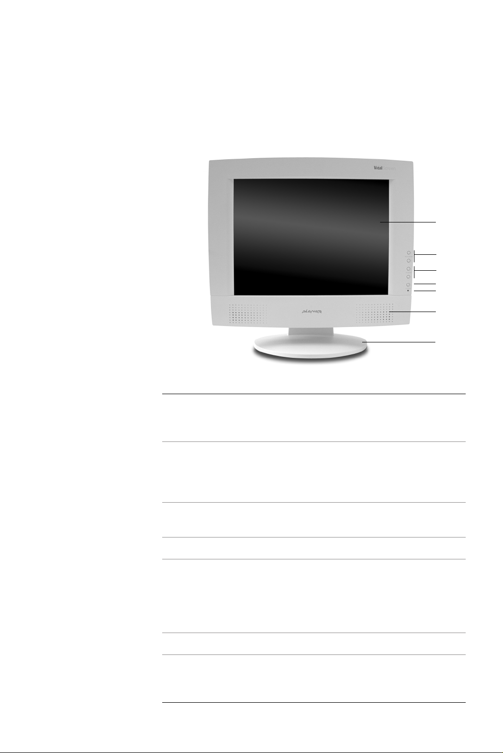
Identifying the Components
The VitalScreen S display provides easy access to all controls and
peripheral ports. The following illustrations of the front and back
panels identify the display controls and ports.
Front panel
1
2
3
4
5
6
7
1 LCD screen A 15-inch diagonal AMLCD. The screen
supports a maximum resolution of
1024 x 768 (XGA).
2 Function UP and
DOWN buttons
3 Adjust PLUS and
MINUS buttons
4 Power ON/OFF Power switch.
5 LED power indicator A light-emitting diode (LED) indicator that
Vertical arrows to navigate the onscreen
display menu horizontally. UP selects the
functions to the left. DOWN selects the
functions to the right.
Controls to change the value of
the selected function.
stays lit when the power is on and the
display is receiving a proper video signal.
The LED blinks slowly when the display is
in power-saving mode.
6 Stereo speakers Two transmission channels for sound.
7 Desk stand Flat-surface support for the display. The
stand allows you to pivot the screen to
various viewing angles.
Page 11
Back panel
About the VitalScreen S 3
412
3
1 Audio Line In Jack for the audio cable. (You can also
connect the CD-ROM Line Out to this jack.)
2 Power input port
(locking mini
DIN connector)
3 Video connector port Port for a 2-meter cable with two 15-pin
4 Touchscreen port Port for the RS-232 cable; used to operate
Port for the power connector.
D-Sub VGA connectors; used to join the
display to the VGA card in your computer.
the optional touch screen. This cable
is provided with the Optional Touch
Screen package.
Page 12
4 Model VSS15X / VSS15X-TR
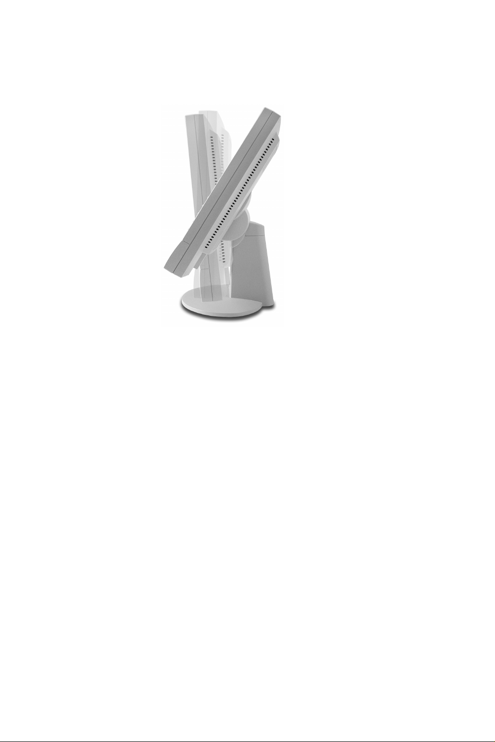
Adjusting the Viewing Angle
You can adjust your VitalScreen S
display to various viewing angles.
This side view of the display shows
the angle settings possible, ranging
from -5 to 25 degrees.
Page 13

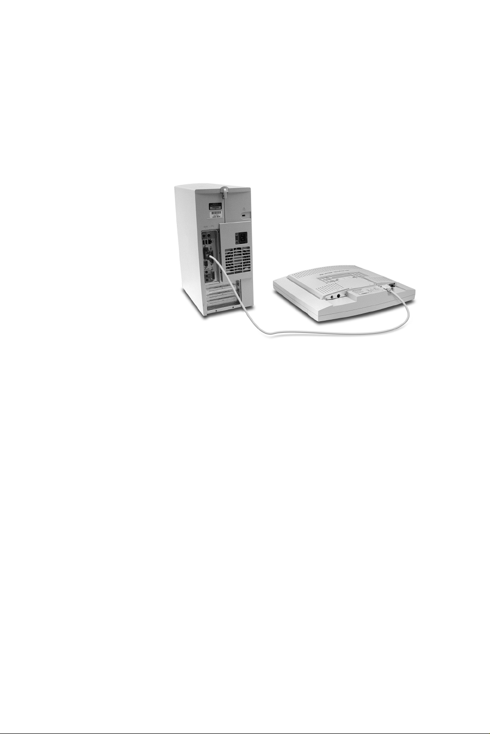
Installing the Display
To install the VitalScreen S display, connect the power supply first.
Next, connect the VGA cable. Then choose whether to connect optional
stereo speakers and touch screen.
Connecting the AC Power
You must use the Ault power adapter with this display unit.
Plug the AC power cord into the power adapter.
Plug the power connector into the locking mini DIN port on
the back panel.
Plug the power cord into a grounded wall outlet.
1
2
3
For added protection, use a surge protector between the power
adapter and the outlet to prevent sudden current variations from
reaching the display.
5
Page 14
6 Model VSS15X / VSS15X-TR
Connecting the Video Cable
1
2
3
Turn off your computer and the display before connecting
the two units.
Plug the video cable into the D-sub VGA connector port on
the back panel.
Plug the other end of the video cable into the VGA port on
the computer.
4
Make sure the cables are properly aligned, then tighten
the connecting screws to ensure a secure connection.
5 Turn on the display first and then the computer.
Page 15

Connecting the Stereo Speakers
1 Plug the audio cable to the Line Out port on the audio card in
your computer.
2 Plug the other end of the audio cable to the Line In jack on
the display.
Installing the Display 7
3 Adjust the volume of the stereo speakers by using the volume
control function on the onscreen display menu.
Note In some instances, the volume control function may be
disabled. If so, the volume is set to the maximum.
Although the display speakers are adequate for most audio
applications, Planar does not recommend using the display
speakers as the exclusive audio source for medical alarms or
applications critical for audio performance.
Page 16

8 Model VSS15X / VSS15X-TR
Connecting the Optional Touch Screen
1 Plug the RS232 cable into the RS232 port on the back panel.
2 Plug the other end of the cable into the RS232 serial port on
your computer.
3 Load the touchscreen driver from the CD enclosed.
Power Management System
The VitalScreen S display complies with the VESA DPMS power
management standard. This standard provides four power-saving
modes, based on the display detecting the horizontal or vertical sync
signals. The following table describes the four modes.
Mode
ON with audio
without audio
Standby 5 watts maximum Blinking green
Suspend 5 watts maximum Blinking green
OFF 5 watts maximum OFF
When the display is in power-saving mode, or when it detects an
incorrect timing, the display screen goes blank and the power LED
indicator blinks.
AC Input Power
(including AC adapter) LED Status
40 watts maximum
37 watts maximum
Steady green
Steady green
Page 17
Display Controls
This chapter explains the onscreen display (OSD) menu: the user
interface for controlling various aspects of the VitalScreen S display.
The VitalScreen S display features an intuitive, menu-driven, onscreen
display. Using the OSD menu, you can adjust the contrast, brightness,
display position, display clarity, color temperature, and stereo speaker
volume, as well as set onscreen display parameters.
Use the push buttons on the front of the display to access the controls.
Access the OSD menu by pressing the Function UP button when the
display is powered-up. If your computer is in power-saving mode, or
is powered-down, the OSD menu is inaccessible.
1
2
3
4
1 Function UP and
DOWN buttons
2 Adjust PLUS and
MINUS buttons
3 Power switch Turns the display ON or OFF when pressed for
4 LED power
indicator
Select functions to the left (UP) or right (DOWN).
Function UP also activates the OSD menu.
Increase or decrease the value of the selected
function. Each button also serves a Function
ENTER button.
a minimum of 2 seconds. Also exits the OSD
main menu and submenus with a quick press.
Is lit continuously when the display is on; blinks
when the display is in power-saving mode.
9
Page 18

10 Model VSS15X / VSS15X-TR
Hot Key Functions
Three Hot Key functions allow you to make quick adjustments to the
display setting, volume, and contrast without accessing the OSD menu.
Auto Adjust. Press the Function
DOWN button to apply a display
setting automatically. A small
Auto Adjust OSD is displayed.
Audio-Volume. Press the Adjust
PLUS button to change the audio
volume directly. A small AudioVolume OSD is displayed.
Contrast. Press the Adjust MINUS
button to change the contrast of
the display directly. A small
contrast OSD is displayed.
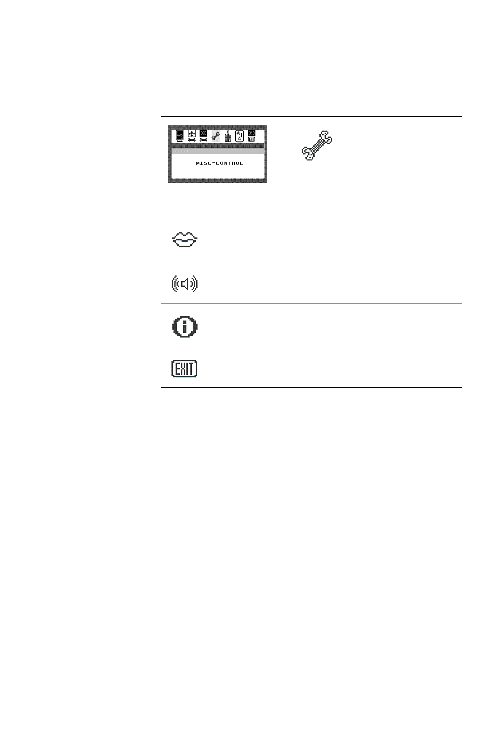
Onscreen Display Main Menu
This screen appears when you access the OSD main menu. The top row
of icons represents the main menus. When a menu item is highlighted,
its submenu, and a description of the submenu item, appears below
the main menu bar.
Main menu
Submenu
Description
Page 19

Function Menus
Display Controls 11
The following tables describe the main menus and submenus.
The Seven Main Menus
Auto Adjust. Allo ws the display to determine and
select the settings that are appropriate for your
system requirements. This function tunes the
display to the video card in your computer.
Monitor-Control. Allows you to adjust the
display characteristics such as the horizontal or
vertical position, display phase, display clock, and
factory reset. Adjusting these settings is necessary
if the results from the Auto Adjust function are not
satisfactory.
OSD-Control. Allows you to adjust the position
and setting of the onscreen display.
MISC-Control. Allows you to select the desired
text language of the onscreen display, adjust the
display speaker volume, and show/display the
current video information being sent to the
display from the video card.
Graphic-Control. Allows you to adjust the
display contrast, brightness, and color settings.
Graph/Text. Allows you to switch DOS text
resolution from 640 x 400 to 720 x 400 pixels.
This function has no effect with graphic operating
systems such as Microsoft
Exit. Closes the onscreen display.
®
Windows®.
Page 20

12 Model VSS15X / VSS15X-TR
Auto Adjust
Allows the display to determine
and select the settings that are
the most appropriate for your
system requirements.
With the Auto Adjust icon
selected, press either Function
Enter button to apply the
display settings automatically.
Monitor–Control
Allows you to adjust the
display characteristics.
With the Monitor-Control icon
selected, press either Function
Enter button to activate the
submenu.
H-Position. Press the Adjust PLUS or MINUS button to move
the display screen horizontally to the desired position.
V-Position. Press the Adjust PLUS or MINUS button to move
the display screen vertically to the desired position.
Phase. Press the Adjust PLUS or MINUS button to fine-tune the
display screen. An improper phase adjustment results in pixel
jitter or display noise.
Clock. Press the Adjust PLUS or MINUS button to stabilize the
display clock timing. An improper clock setting results in wide
vertical bands on the display.
Reset. Press either Function ENTER button to reset
the Monitor-Control submenu values to the factory
default values.
Exit. Press either Function ENTER button to exit the
Monitor-Control submenu.
Page 21

Display Controls 13
OSD–Control
Allows you to adjust the
position of the onscreen
display on the screen.
With the OSD-Control icon
selected, press either Function
Enter button to activate the
submenu.
OSD-H-Position. Press the Adjust PLUS or MINUS button
to move the OSD menu horizontally.
OSD-V-Position. Press the Adjust PLUS or MINUS button
to move the OSD menu vertically.
Exit. Press either Function ENTER button to exit the
OSD-Control submenu.
Page 22
14 Model VSS15X / VSS15X-TR
MISC–Control
Allows you to select the
display language, adjust the
volume setting, and view
system information.
With the MISC-Control icon
selected, press either Function
Enter button to activate the
submenu.
Language. Press the Adjust PLUS or MINUS button to select
the desired OSD display language. Languages supported:
English, German, French, Spanish, and Italian.
Audio Volume . Press the Adjust PLUS or MINUS button
to decrease or increase the volume of the stereo speakers.
Information. When selected, information displayed includes
the current resolution, vertical refresh rate, and display
firmware version.
Exit. Press either Function ENTER button to exit the
MISC-Control submenu.
Page 23

Display Controls 15
Graphic–Control
Allows you to adjust the
display contrast, brightness,
and color settings.
With the Graphic-Control icon
selected, press either Function
Enter button to activate the
submenu.
Contrast. Press the Adjust PLUS or MINUS button to adjust
the difference between the lightest and darkest areas of the
display. The contrast level can range from 0 to 63.
Brightness. Press the Adjust PLUS or MINUS button to adjust
the light level on the display screen Make this adjustment in
conjunction with the Contrast parameter.
Color. Press the Adjust PLUS or MINUS button to select the
display color. The available options are 9300, 6500, and User.
The 9300 and 6500 options allow you to set the Color
Temperature to CIE coordinate value 9300 and 6500 degrees
respectively. Selecting the User option allows you to customize
the Red, Green, and Blue coordinates.
R, G, B. Press the Adjust PLUS or MINUS button to make
individual adjustments to the Red, Green, and Blue gain for
the color temperature. There are 127 levels of adjustments
(0 to 127) available. Before adjusting these fields, select the
User option in the Color submenu.
Auto Level. Press either Function ENTER to automatically
perfect the white balance display.
Exit. Press either Function ENTER button to exit the
Graphic-Control submenu.
Page 24

16 Model VSS15X / VSS15X-TR
Graph/Text
Allows you to change the DOS
resolution from 640 x 400 to
720 x 400.
With the Graph/Text icon
selected, press the Adjust PL US
or MINUS button to change
the resolution from one
setting to the other.
Exit
Allows you to exit the OSD
menu.
With the Exit icon selected,
press either Function ENTER
button.
The OSD menu automatically
exits after a brief period of
inactivity.
Page 25

Technical Information
VSS15X/VSS15X-TR Specification
Panel 15” active matrix color TFT LCD; 1024 (H) x 768 (W) pixels (XGA)
Control functions power Software power switch with LED indicator
(Press a minimum of 2 seconds to turn OFF/ON.)
Onscreen display (OSD) Main Menu Submenu
Monitor Control Auto-Adjust/H-Position/V-Position/Phase/Clock/
Reset/<Graph/Text>/Exit
OSD Control OSD H-Position/OSD V-Position/OSD-Timer/Exit
Graphic Control Contrast/Brightness/Color/RGB/Auto-Level/
Reset/Exit
Misc. Control Language/Audio Volume/Information/Exit
OSD Exit
Display area (mm) 304.1 (W) x 228.1 (H); 380.1 (15-inch) diagonal
Response time (ms), Rise/Fall 20/5 ms typical
Contrast ratio 500:1 typical; 300:1 minimum
2
Brightness (non-touch) 300 cd/m
Viewing angle (degrees) 70/70 (L/R) horizontal
55/65 (U/D) vertical
Pixel pitch (mm) 0.297 (H) x 0.297 (W)
Display colors 16.2 M
Video interface VGA Compatible Analog RGB/ Composite Sync
Scanning frequency (Hz) 24-62k horizontal
56-77 vertical
Number of factory, preset mode 22
Power management Meets VESA DPMS
Power consumption (ON/OFF, W) 40/7 maximum
Dimensions (mm) 408 (W) x 388 (H) x 175 (D)
Net weight (kg) 5 VESA mounting
7.5 deskstand mounting
Power adapter, Ault 12 volts/3.3 amps
Options Wall mount, desk stand, touch screen
Environment Operating temperature: 0 (zero) to 40° C
Relative humidity: 10% to 90%
Audio (Two 1-Watt speakers with amplifier) Yes
Regulatory See “Regulatory Compliance” on page iv
typical; 230 cd/m2 minimum
17
Page 26

Supported Timing
Vertical
Dot Clock
Item Standard Resolution
1 NEC PC98 640x400 25.20 70.15 31.50
2 NEC PC98 640x400 21.05 56.42 24.83
3 MAC 13-inch mode 640x480 30.24 66.67 35.00
4MAC 16-inch mode 832x624 57.28 74.55 49.73
5 MAC 17-inch mode 1024x768 80.00 75.02 60.24
6VGA 640x350 25.18 70.09 31.47
7 VGA 640x400 25.18 70.09 31.47
8VGA 640x480 25.18 59.94 31.47
9 VESA 640x480 31.50 72.81 37.86
10 VESA 640x480 31.50 75.00 37.50
11 VESA 800x600 36.00 56.25 35.16
12 SVGA 800x600 40.00 60.32 37.88
(MHz)
Scanning Frequency
(Hz)
Horizontal
Scanning Frequency
(kHz)
13 VESA 800x600 50.00 72.19 48.08
14 VESA 800x600 49.50 75.00 46.88
15 VGA 720x400 28.32 70.09 31.47
16 XGA 1024x768 65.00 60.00 48.36
17 VESA 1024x768 75.00 70.07 56.48
18 VESA 1024x768 78.75 75.03 60.02
19 1024x768 71.64 66.13 53.96
20 SUN 1024x768 64.13 59.98 48.29
21 SUN 1024x768 74.25 70.04 56.59
22 SUN 1024x768 84.38 77.07 62.04
18
Page 27

Troubleshooting
Problem Display indicates “Over Range”
The frequency range is outside of display specifications, or the
incoming resolution is higher than 1024 x 768.
Frequency range
The incoming frame rate is higher than 75 Hz. The screen display may
not be centered and this warning message appears
Incoming resolution
The incoming resolution is higher than 1024 x 768. The video data turns
off and this warning message appears.
Solution Check that the scanning frequency is in a horizontal range of 24 to
62 kHz and a vertical range of 55 to 77 Hz. Or check that the display
resolution is set to 1024 x 768 or lower.
19
Page 28

20 Appendix C
Problem Display indicates “No Signal”
When there is no video-input signal from the source video port,
the OSD shows this message.
Solution Check that the video cable is connected securely to the computer and
the display.
Page 29

Index
A
AC power, connecting, 5
Adjust button, 2, 9
adjusting display, 9
adjusting viewing angle, 4
audio line, 3
Auto Adjust menu, 11, 12
B
back panel, 3
C
cleaning instructions, vii
components, identifying, 2
connecting
AC power
stereo speakers, 7
touch screen, 8
VGA cable, 6
controls, display, 9
customer support, 25
, 5
D
desk stand, 2
DIN connector, 3
display
adjusting
back panel, 3
cleaning, vii
controls, menu, 9
front panel, 2
installing, 5
setup, 1
troubleshooting, 19
unpacking, 1
viewing angle, adjusting, 4
DPMS, 8
, 9
I
identifying components, 2
information
ordering parts
product, vi
technical, 17
installing display, 5
, 26
L
LCD screen, 2
cleaning, vii
troubleshooting, 20
M
menu
Auto Adjust
Exit, 11, 16
Graph/Text, 11, 16
Graphic-Control, 11, 15
main, onscreen display, 11
MISC-Control, 11, 14
Monitor-Control, 11, 12
OSD-Control, 11, 13
MISC-Control menu, 11, 14
Monitor-Control menu, 11, 12
, 11, 12
O
onscreen display (OSD) menu, 11
ordering parts, 26
OSD-Control menu, 11, 13
P
power
indicator
management system, 8
switch, 2
product information, vi
, 2
E
Exit menu, 11, 16
F
front panel, 2
Function buttons, 2
G
Graph/Text menu, 11, 16
Graphic-Control menu, 11, 15
R
repair service, 25
RS232 connector, 3
S
safety instructions, vi
selecting workspace, 1
stereo speakers, 2, 7
supported timing, 18
21
Page 30

22 Index
T
technical information, 17
timing, supported, 18
touch screen
cleaning
connecting, 8
troubleshooting, 19
, vii
U
unpacking display, 1
V
VESA DPMS, 8
VGA
cable, connecting
connector, 3
viewing angle, adjusting, 4
, 6
W
warranty, 23
workspace, selecting, 1
Page 31

Description of Warranty
Planar Systems, Inc. (Planar) warrants that the goods sold hereunder
will be free of defects in materials and workmanship, and such goods
will substantially conform to the specifications furnished by Planar, and
to any drawings or specifications furnished to Planar by the Buyer if
approved by Planar. This warranty shall be effective only if Planar
receives notice of such defect or nonconformance during the period
of the warranty. Sole and exclusive liability of Planar for breach of
warranty shall be, at the company’s option, to repair or replace the
Planar product(s) with refurbished units or provide a credit to Buyer
in the amount of the purchase price.
Commencement
and duration of
warranty
Place of repair or
replacement
The warranty period begins on the date of shipment from Planar. The
goods sold hereunder are warranted for a period of 36 months from
date of shipment unless otherwise agreed to by Buyer and Planar. No
extension of the warranty will be given during the time the goods are in
the possession of Planar.
To obtain service under this warranty, Buyer must notify Planar of the
defect before expiration of the warranty period and request a “Return
Material Authorization Number (RMA).” If the configuration has been
modified in any manner, the product must be returned to its original
configuration before any warranty service will be performed by Planar.
No goods are to be returned to Planar without prior authorization.
Buyer will be responsible for packaging and shipping the defective
goods to the appropriate Planar Service Facility. For North America,
the service facility is located in Espoo, Finland.
MORE
Page 32

Limitation of
warranty
The foregoing warranty shall not apply to defects resulting from
(a) improper or inadequate maintenance by Buyer; (b) unauthorized
modification of the goods; (c) operations of the goods outside the
environmental specifications of the goods; (d) neglect, misuse, or
abuse of the goods; or (e) modification or integration with other goods
not covered by the Planar warranty when such modification or
integration increases the likelihood of damage to the goods.
THE WARRANTY IS GIVEN BY Planar IN LIEU OF ANY OTHER
WARRANTIES, EXPRESS OR IMPLIED. Planar DISCLAIMS ANY IMPLIED
WARRANTIES OF MERCHANTABILITY OR FITNESS FOR A PARTICULAR
PURPOSE. ITS RESPONSIBILITY TO REPAIR OR REPLACE DEFECTIVE
PRODUCTS IS THE SOLE AND EXCLUSIVE REMEDY PROVIDED TO THE
BUYER FOR BREACH OF THIS WARRANTY. Planar WILL NOT BE LIABLE
FOR ANY INDIRECT, SPECIAL, INCIDENTAL, OR CONSEQUENTIAL
DAMAGES IRRESPECTIVE OF WHETHER Planar HAS ADVANCE NOTICE
OF THE POSSIBILITY OF SUCH DAMAGES.
The warranty set forth above shall not be enlarged, diminished, or
affected by, and no obligation or liability shall arise from Planar, any
authorized dealer, or any other person’s rendering of technical advice,
assistance, or services in connection with the Buyer’s order of the goods
furnished hereunder. The Buyer is not relying on skill or judgment of
Planar to select or furnish suitable goods.
MORE
Page 33

Installation Planar makes no warranty with respect to any installation of Planar
product(s) by Planar, any authorized dealer, or any other person.
Technical
assistance
Repair service In North America, call Planar at (503) 748-1100 between 8 A.M. and
In North America, call 1 (866) PLANAR1 between 8 A.M. and 5 P.M. Pacific
time, Monday through Friday, or send a description of your technical
issues and e-mail address to medicalsupport@planar.com.
In Europe, call +358 9 420 01 between 8 A.M. and 4 P.M. Finnish
time (Eastern European time), Monday through Friday, or send
a description of your technical issues and e-mail address to
medicalsupport@planar.com.
4 P.M. Pacific time, Monday through Friday, or fax your request to
(503) 748-1493. You need the unit’s serial number and a brief
description of the problem to receive an RMA number.
In Europe, call Planar Customer Service at +358 9 420 01 between 8 A.M.
and 4 P.M. Eastern European time, Monday through Friday, or fax your
request to +358 9 420 0200. You need the unit’s serial number and
a brief description of the problem to receive an RMA number.
To protect Planar employees from potential health hazards, Planar
requires that the RMA product be disinfected before returning to Planar
for service. Any product not cleaned prior to shipment will be returned
to the customer.
Returns are not accepted without an assigned RMA number.
In-transit damage is not covered by the warranty. Insure your shipment.
Planar only pays for the return shipment by surface transportation.
It is responsibility of the sender to prepay transportation charges.
Page 34

Ordering Information
Non-touch display Use the information in these tables to order parts for
the VSS15X non-touch display.
VSS15X Display Part Number
VSS 15X 15-inch XGA VitalScreen S
Medically Certified Display with
desk stand and US power cord
VSS 15X 15-inch XGA VitalScreen S
Medically Certified Display with
desk stand and European power cord
VSS 15X 15-inch XGA VitalScreen S
Medically Certified Display with
mounting plate and US power cord
VSS 15X 15-inch XGA VitalScreen S
Medically Certified Display with
mounting plate and European power cord
Accessories Original Part Replacement Part
US power cord 903-0169-00
European power cord 903-0251-00
VGA cable 903-0454-00 903-0167-00
997-2261-01
997-2262-01
997-2265-01
997-2266-01
Audio cable 903-0455-00 903-0168-00
Power adapter, Ault 903-0013-01
Page 35

Resistive-touch
display
Use the information in these tables to order parts for
the VSS15X-TR resistive-touch display.
VSS15X-TR Display Part Number
VSS 15X-TR 15-inch XGA VitalScreen S
Medically Certified Display with
desk stand and US power cord
VSS 15X-TR 15-inch XGA VitalScreen S
Medically Certified Display with
desk stand and European power cord
VSS 15X-TR 15-inch XGA VitalScreen S
Medically Certified Display with
mounting plate and US power cord
VSS 15X-TR 15-inch XGA VitalScreen S
Medically Certified Display with
mounting plate and European power cord
Accessories Original Part Replacement Part
US power cord 903-0169-00
European power cord 903-0251-00
VGA cable 903-0454-00 903-0167-00
997-2401-01
997-2402-01
997-2403-01
997-2404-01
Audio cable 903-0455-00 903-0168-00
Touchscreen cable 903-0456-00 903-0233-00
Power adapter, Ault 903-0013-01
Page 36

Americas Sales
Planar Systems, Inc.
1195 NW Compton Drive
Beaverton, OR 97006-1992 USA
(503) 748-1100 phone
(503) 748-1493 fax
sales@planar.com
Medical Sales
Planar Systems, Inc.
400 Fifth Avenue
Waltham, MA 02451-8738 USA
(781) 895-1155 phone
(781) 895-1133 fax
medicalsales@planar.com
Europe & Asia-Pacific Sales
Planar Systems, Inc.
Olarinluoma 9, P. O. Box 46
FIN-02201 Espoo, Finland
+ 358 9 420 01 phone
+ 358 9 420 0200 fax
intlsales@planar.com
 Loading...