

Page 1
QUICK LINKS
Contents
Index
Ordering Parts
Product Information
Regulatory Compliance
Warranty
GETTING STARTED
About the Display
Unpack Display
Identify Components
INSTALLING THE DISPLAY
Connect Power
Connect Video
Connect Audio
Connect Touch Screen
Power Management System
USING THE CONTROLS
Display Controls
OSD Menu
Function Menus
OSD Lockout
DDC Change
VS15 Display
VS15XAD / VS15XAD-TR
Operations Manual
APPENDIXES
Technical Information
Troubleshooting
www.planar.com
Page 2

QUICK LINKS
Contents
Index
Ordering Parts
Product Information
Regulatory Compliance
Warranty
GETTING STARTED
About the Display
Unpack Display
Identify Components
INSTALLING THE DISPLAY
Connect Power
Connect Video
Connect Audio
Connect Touch Screen
Power Management System
USING THE CONTROLS
Display Controls
OSD Menu
Function Menus
OSD Lockout
DDC Change
APPENDIXES
Technical Information
Troubleshooting
Copyright © 2004 Planar Systems, Inc. All rights reserved.
This document contains proprietary information of Planar Systems, Inc. It is the exclusive
property of Planar. It may not be reproduced or transmitted, in whole or in part, without
a written agreement from Planar. No patent or other license is granted to this information.
The software, if any, described in this document is furnished under a license agreement.
The software may not be used or copied except as provided in the license agreement.
Planar Systems, Inc. provides this publication as is without warranty of any kind, either
express or implied, including but not limited to the implied warranties of merchantability
or fitness for a particular purpose. Planar may revise this document from time to time
without notice. Some states or jurisdictions do not allow disclaimer of express or implied
warranties in certain transactions; therefore, this statement may not apply to you.
Information in this document about products not manufactured by Planar is provided
without warranty or representation of any kind, and Planar will not be liable for any
damages resulting from the use of such information.
Planar is a registered trademark and VS15 a trademark of Planar Systems, Inc.
All other trademarks are the property of their respective owners.
DOCUMENT HISTORY
Date Description
August 2004 020-0158-00C
August 2003 020-0158-00B
May 2001 020-0158-00A
America Sales
Planar Systems, Inc.
1195 NW Compton Drive
Beaverton, OR 97006-1992 USA
(503) 748-1100 phone
(503) 748-1493 fax
Medical Sales
Planar Systems, Inc.
400 Fifth Avenue
Waltham, MA 02451-8738 USA
(781) 895-1155 phone
(781) 895-1133 fax
Europe & Asia-Pacific Sales
European Representative
Planar Systems, Inc.
Olarinluoma 9, P. O. Box 46
FIN-02201 Espoo, Finland
+ 358 9 420 01 phone
+ 358 9 420 0200 fax
medicalsales@planar.com
medicalsupport@planar.com
www.planar.com
VS15 Display
ii
Page 3

QUICK LINKS
Contents
Index
Ordering Parts
Product Information
Regulatory Compliance
Warranty
GETTING STARTED
About the Display
Unpack Display
Identify Components
INSTALLING THE DISPLAY
Connect Power
Connect Video
Connect Audio
Connect Touch Screen
Power Management System
USING THE CONTROLS
Display Controls
OSD Menu
Function Menus
OSD Lockout
DDC Change
APPENDIXES
Technical Information
Troubleshooting
Contents
Regulatory Compliance
Product Information
Getting Started
1
About the VS15 Display
Unpack the Display
Identify the Components
2
Installing the Display
Connect the AC Power
Connect the Video Cable
Connect the Audio Cable
Connect the Optional Touch Screen
Power Management System
3
Using the Display Controls
Display Controls
Onscreen Display Main Menu
Function Menus
Onscreen Display Lockout
DDC Change
Appendix A: Technical Information
Appendix B: Troubleshooting
Index
Overview of Standard Warranty
Ordering Information
. . . . . . . . . . . . . . . . . . . . . . . . . . . . . . . . . . . . . iv
. . . . . . . . . . . . . . . . . . . . . . . . . . . . . . . . . . . . . . . vi
. . . . . . . . . . . . . . . . . . . . . . . . . . . . . . . . . . . . . .1
. . . . . . . . . . . . . . . . . . . . . . . . . . . . . . . . . . . . . . . .2
. . . . . . . . . . . . . . . . . . . . . . . . . . . . . . . . . . . .3
. . . . . . . . . . . . . . . . . . . . . . . . . . . . . . . . . . . . . .5
. . . . . . . . . . . . . . . . . . . . . . . . . . . . . . . . . . . . .6
. . . . . . . . . . . . . . . . . . . . . . . . . . . . . . . . . . . . .7
. . . . . . . . . . . . . . . . . . . . . . . . . . . . . .8
. . . . . . . . . . . . . . . . . . . . . . . . . . . . . . . . . . .9
. . . . . . . . . . . . . . . . . . . . . . . . . . . . . . . . . . . . . . . . .10
. . . . . . . . . . . . . . . . . . . . . . . . . . . . . . . . .11
. . . . . . . . . . . . . . . . . . . . . . . . . . . . . . . . . . . . . . . . . .12
. . . . . . . . . . . . . . . . . . . . . . . . . . . . . . . . . . .18
. . . . . . . . . . . . . . . . . . . . . . . . . . . . . . . . . . . . . . . . . . . .19
. . . . . . . . . . . . . . . . . . . . . . . . . . .20
. . . . . . . . . . . . . . . . . . . . . . . . . . . . . . .21
. . . . . . . . . . . . . . . . . . . . . . . . . . . . . . . . . . . . . . . . . . . . . . . .22
. . . . . . . . . . . . . . . . . . . . . . . . . . . . . .24
. . . . . . . . . . . . . . . . . . . . . . . . . . . . . . . . . . . . .27
VS15 Display
iii
Page 4

QUICK LINKS
Contents
Index
Ordering Parts
Product Information
Regulatory Compliance
Warranty
GETTING STARTED
About the Display
Unpack Display
Identify Components
INSTALLING THE DISPLAY
Connect Power
Connect Video
Connect Audio
Connect Touch Screen
Power Management System
USING THE CONTROLS
Display Controls
OSD Menu
Function Menus
OSD Lockout
DDC Change
Regulatory Compliance
This display has been tested and certified to international medical safety standards IEC/EN 60601-1
and IEC/EN 60601-1-2, and is certified to meet C22.2 No. 601.1-M90 (C US Mark).
Because many medical offices are located in residential areas, the medical display, in addition to
meeting medical requirements, has also been tested and found to comply with the limits for
Federal Communications Commission (FCC) Class B computing devices in a typically configured
system. It is the system integrator or configurer’s responsibility to test and ensure that the entire
system complies with applicable electromagnetic compatibility (EMC) laws.
Planar Systems, Inc. has made great efforts to support the medical device industry, in particular,
medical device manufacturers and medical device system integrators. We offer state-of-the-art
color displays that are compliant with worldwide accepted medical device safety standards, and for
the European market, CE-marked displays based on compliance with counsel directive 93/42/EEC
commonly referred to as the Medical Device Directive (MDD). The following summarizes our
qualification of these displays as it relates to compliance with the MDD.
The European Medical Device Directive requires that the intended use of the device be defined. The
intended use of these displays is “to display alphanumeric, graphic, and image data as inputted
from any type of medical device.” These displays do not provide a measurement function in any
way, and it is the device and systems manufacturer’s responsibility to verify its function in the
integrated device or system.
The display was classified as required by the MDD according to Annex IX of the directive and the
medical device (MEDDEV) guidance available at the time of classification. Because the display uses
electrical energy and has no direct patient connections and—by itself—no medical utility, the
display is classified according to Rule 12 as an MDD Class I device-component or accessory. The
MDD states that manufacturers of Class I medical devices or accessories shall satisfy the
requirements in regard to design and manufacturing controls, that is, the applicable assessment
route to be used for CE-marking under the MDD, and it shall carry the CE mark according to Annex
XII of the directive, with no notified body annotation.
MORE
APPENDIXES
Technical Information
Troubleshooting
VS15 Display
iv
Page 5

QUICK LINKS
Contents
Index
Ordering Parts
Product Information
Regulatory Compliance
Warranty
GETTING STARTED
About the Display
Unpack Display
Identify Components
INSTALLING THE DISPLAY
Connect Power
Connect Video
Connect Audio
Connect Touch Screen
Power Management System
USING THE CONTROLS
Display Controls
OSD Menu
Function Menus
OSD Lockout
DDC Change
APPENDIXES
Technical Information
Troubleshooting
The applicable safety standards for an MDD Class I display are IEC/EN 60601-1:1900 along with
Amendments 1 and 2. To help the medical device designer evaluate the suitability of these displays,
Planar has also conducted EMC testing to IEC 60601-1-2 as it can be applied. The display with its
power supply alone does not represent a functional medical device. Hence, Planar configured a
minimal operating system to exercise the display. The resulting data are made available to
interested parties.
This is informative data, not certification data. Certification data must be obtained by the device or
system integrator according to Article 12 of the MDD titled “Particular procedure for systems and
procedure packs.” Paragraph 2 clearly outlines the device or system integrator’s responsibility in
this matter.
In summary, Planar Systems, Inc. is CE-marking these displays under the Medical Device Directive,
which establishes compliance to the basic medical safety standards. However, EMC compliance can
only be accomplished in the configured medical device or system and is the responsibility of the
device or system manufacturer. Planar has the necessary documentation such as IEC 60601-1
notified body and other third-party test reports and certifications, a risk/hazard analysis, an
essential requirements checklist, and the Planar International Electrotechnical Commission (IEC)
declaration of conformity.
Planar Systems, Inc., located in Beaverton, Oregon, USA, is the manufacturer of these displays in
the meaning of the directive. As required by the MDD in Article 14, Planar Systems, Inc., not residing
in the European Economic Area (EEA), has a European representative, Planar Systems, Inc.—
Olarinluoma 9, P.O. Box 46, FIN-02201Espoo, Finland (phone + 358 9 420 01; fax +358 9 420 0200).
In the opinion of Planar Systems, Inc. registration required to put this device into commerce is the
responsibility of the medical device/system manufacturer, and Planar supports this requirement by
providing a European commission (EC) declaration of conformity. If Planar supplies a display to an
end user, rather than a device manufacturer, it is the end user’s responsibility to ensure continued
compliance with the MDD of the system in which the display is integrated.
For vigilance reporting as required under Article 10 of the MDD, Planar Systems, Inc. will provide
any information requested by competent authority to support any reported incident investigation
by such an authority.
European Union Declaration of Conformity for Medical Applications
A Declaration of Conformity has been filed for this product. For additional copies of the Declaration
of Conformity document, contact Planar Systems, Inc.
VS15 Display
v
Page 6

QUICK LINKS
Contents
Index
Ordering Parts
Product Information
Regulatory Compliance
Warranty
GETTING STARTED
About the Display
Unpack Display
Identify Components
INSTALLING THE DISPLAY
Connect Power
Connect Video
Connect Audio
Connect Touch Screen
Power Management System
USING THE CONTROLS
Display Controls
OSD Menu
Function Menus
OSD Lockout
DDC Change
APPENDIXES
Technical Information
Troubleshooting
Product Information
Safety instructions
Store the display in its original shipping carton when it is not in operation for extended
periods of time. Use the original packing materials and carton when shipping the display.
• Do not place the display near a window. Exposing the display to rain, water,
moisture, or direct sunlight can damage it.
• Do not place anything on top of the video cable. Place the cable clear of foot traffic.
• Do not apply excessive pressure to the screen. Excessive pressure may cause permanent
damage to the display.
• Refer all servicing to qualified personnel to maintain your warranty. The display and power
adapter units contain no user-serviceable parts.
• Do not cover or obstruct the venting holes on the back of the display.
• Make sure the display storage area has a temperature range between -20 and 65 degrees
Celsius. Storing your display outside this range could result in permanent damage.
• Do not expose the display to liquid or drop it. If the case has been damaged, the unit
may pose a shock or fire hazard. Unplug the unit immediately and call customer support for
assistance.
• Replace any cord or cable that is frayed or damaged with another of the same type and
rating as supplied by Planar. The safety and regulatory listings and certifications are based
on the cable supplied by Planar.
• Use only the power adapter that has been tested and approved for use with this display
product. The power adapter must be plugged into a grounded power outlet.
• Do not use the power adapter near inflammable anesthetics.
• Do not immerse the power adapter in liquid, or a safety hazard could arise during use.
• Disconnect the display from the mains by pulling the mains power cord/mains plug.
• Install the display near a wall outlet that is easily accessible.
MORE
VS15 Display
vi
Page 7

QUICK LINKS
Contents
Index
Ordering Parts
Product Information
Regulatory Compliance
Warranty
GETTING STARTED
About the Display
Unpack Display
Identify Components
INSTALLING THE DISPLAY
Connect Power
Connect Video
Connect Audio
Connect Touch Screen
Power Management System
Cleaning instructions
The VS15XAD model continues to operate while being cleaned in a fashion normal for
a hospital environment. The display withstands nonabrasive cloths and cleaning solutions
used on similar equipment. Use a damp cloth with the cleaning solution for all surfaces. Drip
protection is provided in accordance with IPX1 rating defined in the IEC/EN60529 standard.
Still, do not spray liquid cleaners directly onto the screen.
To clean the screen
1
Stand away from the display and dampen a clean nonabrasive cloth with the cleaning
solution. (You can also use 70% isopropyl alcohol for the touchscreen surface.)
2
Wipe the screen gently with the cloth. Do not apply excessive pressure.
3
Dry the screen with a clean nonabrasive cloth to remove any residue.
Disposal information
The VS15XAD model contains cold cathode fluorescent lamps, which contain a maximum of
12 milligrams (3 milligrams per lamp) of mercury. Follow local ordinances or regulations for
its disposal.
Possible cleaning solutions
• 70% isopropyl alcohol
• 1.6 percent aqueous ammonia
• Cidex® (2.4 percent
glutaraldehyde solution)
• Sodium hypochlorite (bleach) 10%
• “Green soap” United States
Pharmacopoeia (USP)
• 0.5 percent Chlorhexidine in 70%
isopropyl alcohol
• Ovation®
• Formula 409®
• Fantastic®
• WexCide®
USING THE CONTROLS
Display Controls
OSD Menu
Function Menus
OSD Lockout
DDC Change
APPENDIXES
Technical Information
Troubleshooting
VS15 Display
MORE
vii
Page 8
QUICK LINKS
Contents
Index
Ordering Parts
Product Information
Regulatory Compliance
Warranty
GETTING STARTED
About the Display
Unpack Display
Identify Components
INSTALLING THE DISPLAY
Connect Power
Connect Video
Connect Audio
Connect Touch Screen
Power Management System
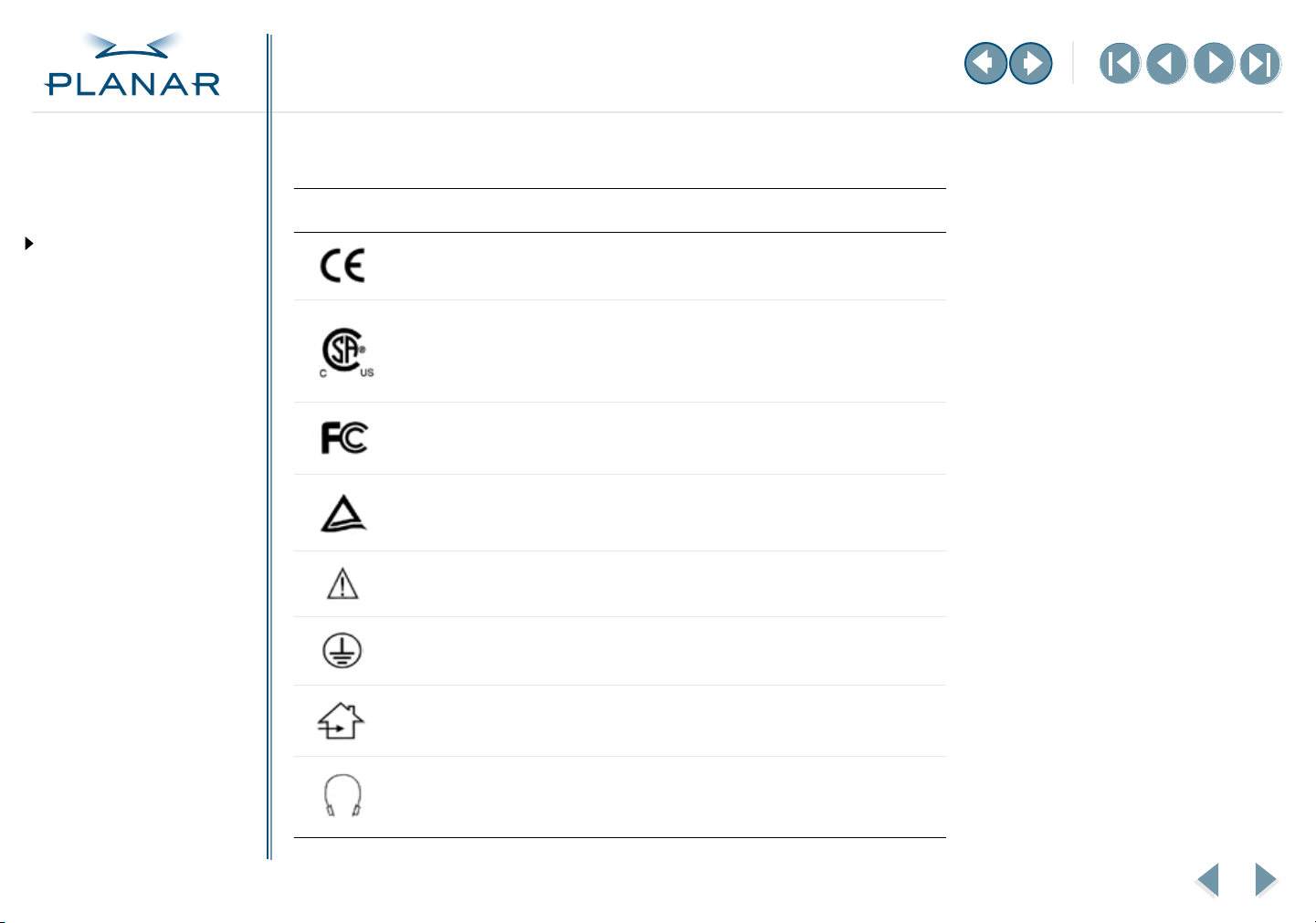
Symbol explanations
These symbols may appear on the display or power adapter.
Symbol Description
Proof of conformity to applicable European Economic Community Council
directives.
The product has been tested and certified by CSA to C22.2 No. 601.1-M1990.
If this mark appears with the indicators "C" and "US," the product is certified
for the Canadian and U.S. markets, meeting the applicable Canadian and
U.S. standards.
The product has been tested to comply with FCC Class B standards.
The product has been tested and certified by TÜV Rheinland in accordance
with EN6061-1.
More information available in accompanying documents.
USING THE CONTROLS
Display Controls
OSD Menu
Function Menus
OSD Lockout
DDC Change
APPENDIXES
Technical Information
Troubleshooting
VS15 Display
Protective earth ground.
Indoor use only.
Socket for headphones.
viii
Page 9

QUICK LINKS
Contents
Index
Ordering Parts
Product Information
Regulatory Compliance
Warranty
About the VS15 Display
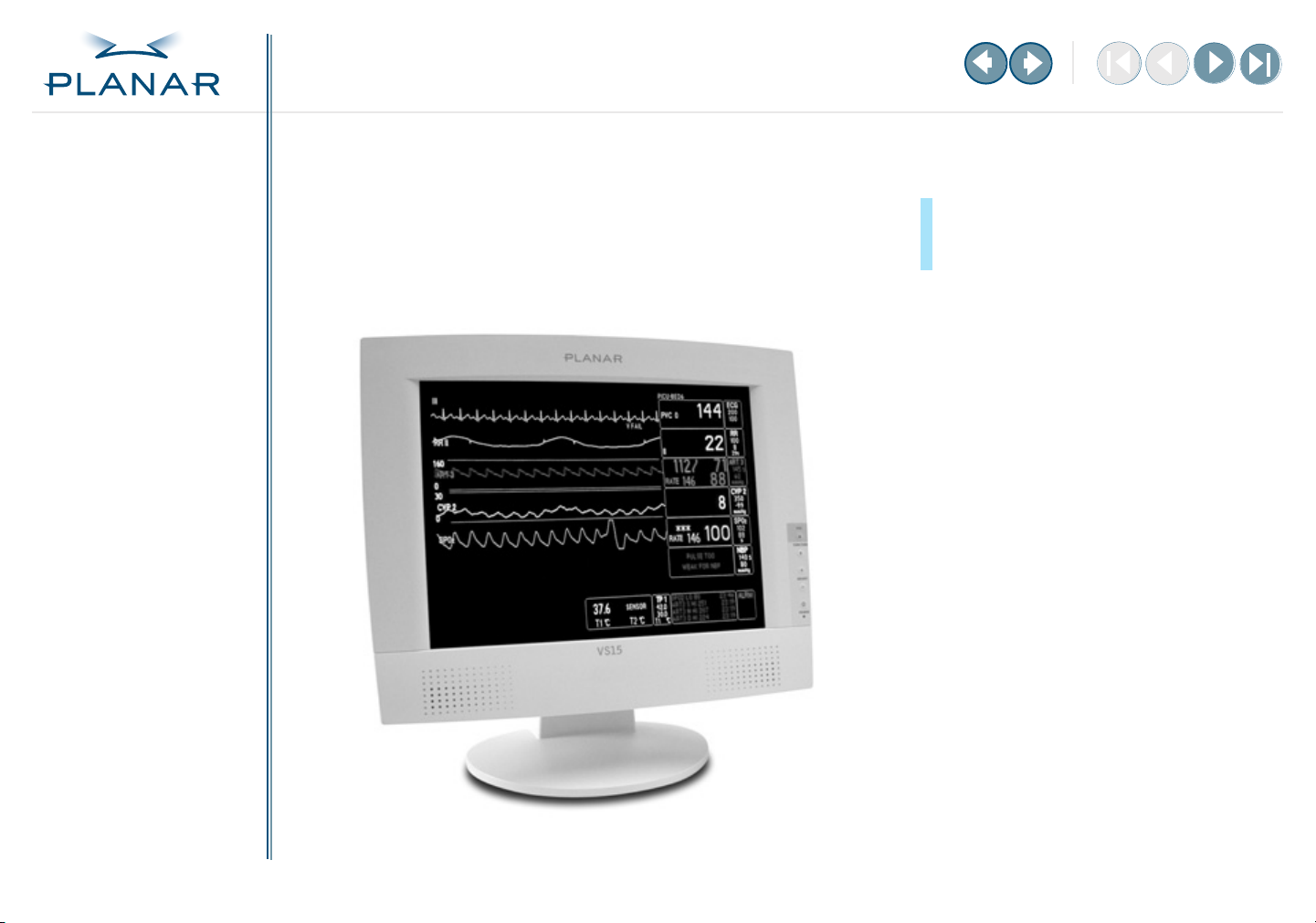
The Planar VS15XAD VS15 display is a high-resolution color monitor designed to be
versatile and easy to use. This display can accept either analog or digital video input
and display most video standards from 640 x 480 (Video Graphics Array, or VGA,
standard) to 1024 x 768 (Extended Graphics Array, or XGA, standard). The controls
located on the front panel allow you to easily adjust the display’s parameters using
onscreen menus.
GETTING STARTED
About the Display
Unpack Display
Identify Components
INSTALLING THE DISPLAY
Connect Power
Connect Video
Connect Audio
Connect Touch Screen
Power Management System
USING THE CONTROLS
Display Controls
OSD Menu
Function Menus
OSD Lockout
DDC Change
APPENDIXES
Technical Information
Troubleshooting
The display’s video input is a single-link, transition minimized differential signaling
(TMDS) digital visual interface (DVI). It is compliant with the Digital Display Working
Group (DDWG) DVI standard. This interface produces the sharpest display image
possible with little need for adjustment. The setup is Plug and Play.
The display uses a mounting plate that conforms to the Video Electronics Standards
Association (VESA) mounting standard.* That configuration allows the display to be
mounted in a variety of ways, such as on a wall bracket or swing arm. An alternate
configuration with a desk stand is also available for easy use on flat work surfaces.
The architecture of this display incorporates an active-matrix LCD panel that
produces a clear display with low radiation emission, greatly reducing the radiationrelated health concerns associated with CRT monitors.
* The VESA Flat Panel Monitor Physical Mounting Interface (FPMPMI) Standard defines physical
mounting interfaces for flat-panel displays, corresponding standards for flat-panel display mounting
devices, and associated cable, cable connectors, and power adapter location guidelines. For more
information, go to http://www.vesa.org.
VS15 Display
1
Page 10

QUICK LINKS
Contents
Index
Ordering Parts
Product Information
Regulatory Compliance
Warranty
GETTING STARTED
About the Display
Unpack Display
Identify Components
INSTALLING THE DISPLAY
Connect Power
Connect Video
Connect Audio
Connect Touch Screen
Power Management System
Unpack the Display
Inspect the display and other package contents for shipping damage that could
cause a fire or shock hazard. Report any shipping damage to the carrier or
transportation company immediately, and speak with a customer service
representative for assistance.
Make sure the following items are included:
• Active-matrix LCD panel
• Desk stand or VESA mounting plate
• Analog video cable (DVI-VGA)
• Digital video cable (DVI-DVI)
• Stereo audio cable
• Touchscreen cable (VS15XAD-TR only)
• AC power adapter with 1.5-meter (5-foot) cable
•Medical-grade power cord (US or European)
• CD with touchscreen driver and PDF of this manual
• EU Declaration of Conformity
Selecting a workspace
Before you unpack the VS15 display,
select a suitable workspace for the
display and computer. You need
a stable, level, and clean surface near
a wall outlet.
Avoid setting up the display near
a window where sunlight often
comes in. You will have difficulty
seeing the screen with glare
reflecting off the display.
This display is cooled by natural
convection. Do not block the cooling
vents. Place the display in a location
that allows sufficient airflow to ensure
proper ventilation.
USING THE CONTROLS
Display Controls
OSD Menu
Function Menus
OSD Lockout
DDC Change
APPENDIXES
Technical Information
Troubleshooting
Keep all packing material in case you need to ship, store, or return the display.
VS15 Display
2
Page 11
QUICK LINKS
Contents
Index
Ordering Parts
Product Information
Regulatory Compliance
Warranty
GETTING STARTED
About the Display
Unpack Display
Identify Components
INSTALLING THE DISPLAY
Connect Power
Connect Video
Connect Audio
Connect Touch Screen
Power Management System
USING THE CONTROLS
Display Controls
OSD Menu
Function Menus
OSD Lockout
DDC Change
APPENDIXES
Technical Information
Troubleshooting
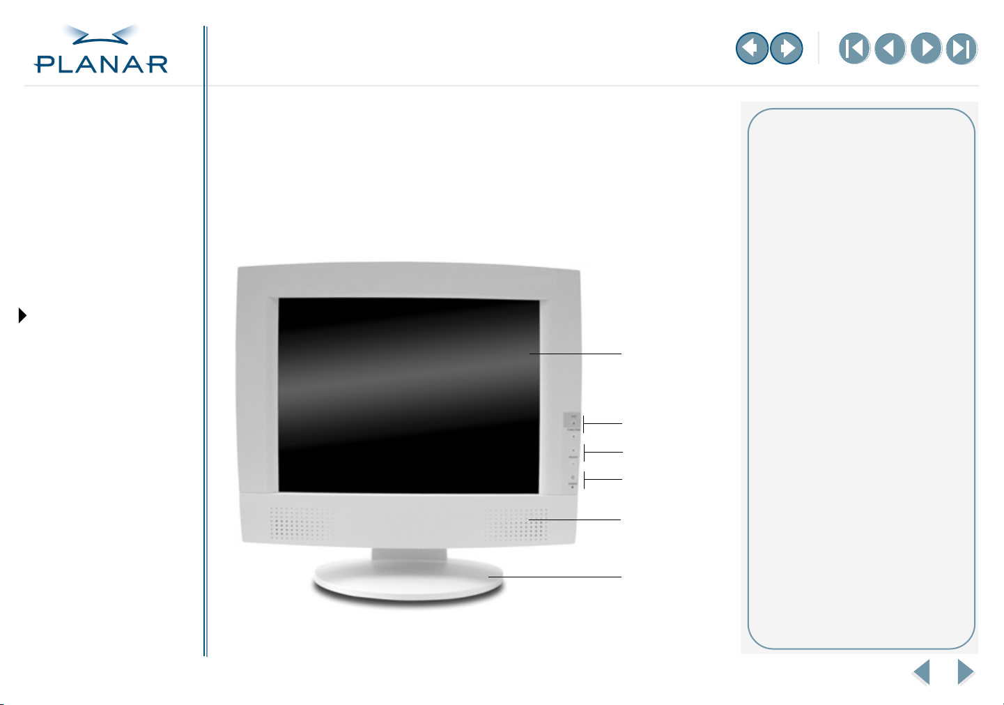
Identify the Components
The VS15 display provides easy access to all controls and peripheral ports. Check
the following illustrations of the front and back panels to identify the display
controls and ports.
Front panel
1
2
3
4, 5
6
7
MORE
Legend
1 LCD screen
A 15-inch diagonal active-matrix
LCD panel. The panel can produce
most display standards from 640 x
480 VGA to 1024 x 768 XGA.
2 Function UP and DOWN buttons
UP activates the OSD menu and
navigates the OSD main menu;
DOWN navigates the submenus.
3 Adjust PLUS and MINUS buttons
Controls to change the value of
the selected icon.
4 Power switch
Depress this button for 2 seconds
to turn the display on/off.
5 Power ON Indicator
The LED indicator is illuminated
when the power is on and blinks
when the display is in powersaving mode.
6 Stereo speakers
Built-in amplifier and stereo
speakers for sound.
7 Desk stand
Flat-surface support for the
display. The stand allows you
to tilt the screen to various
viewing angles.
VS15 Display
3
Page 12
QUICK LINKS
Contents
Index
Ordering Parts
Product Information
Regulatory Compliance
Warranty
GETTING STARTED
About the Display
Unpack Display
Identify Components
INSTALLING THE DISPLAY
Connect Power
Connect Video
Connect Audio
Connect Touch Screen
Power Management System
USING THE CONTROLS
Display Controls
OSD Menu
Function Menus
OSD Lockout
DDC Change
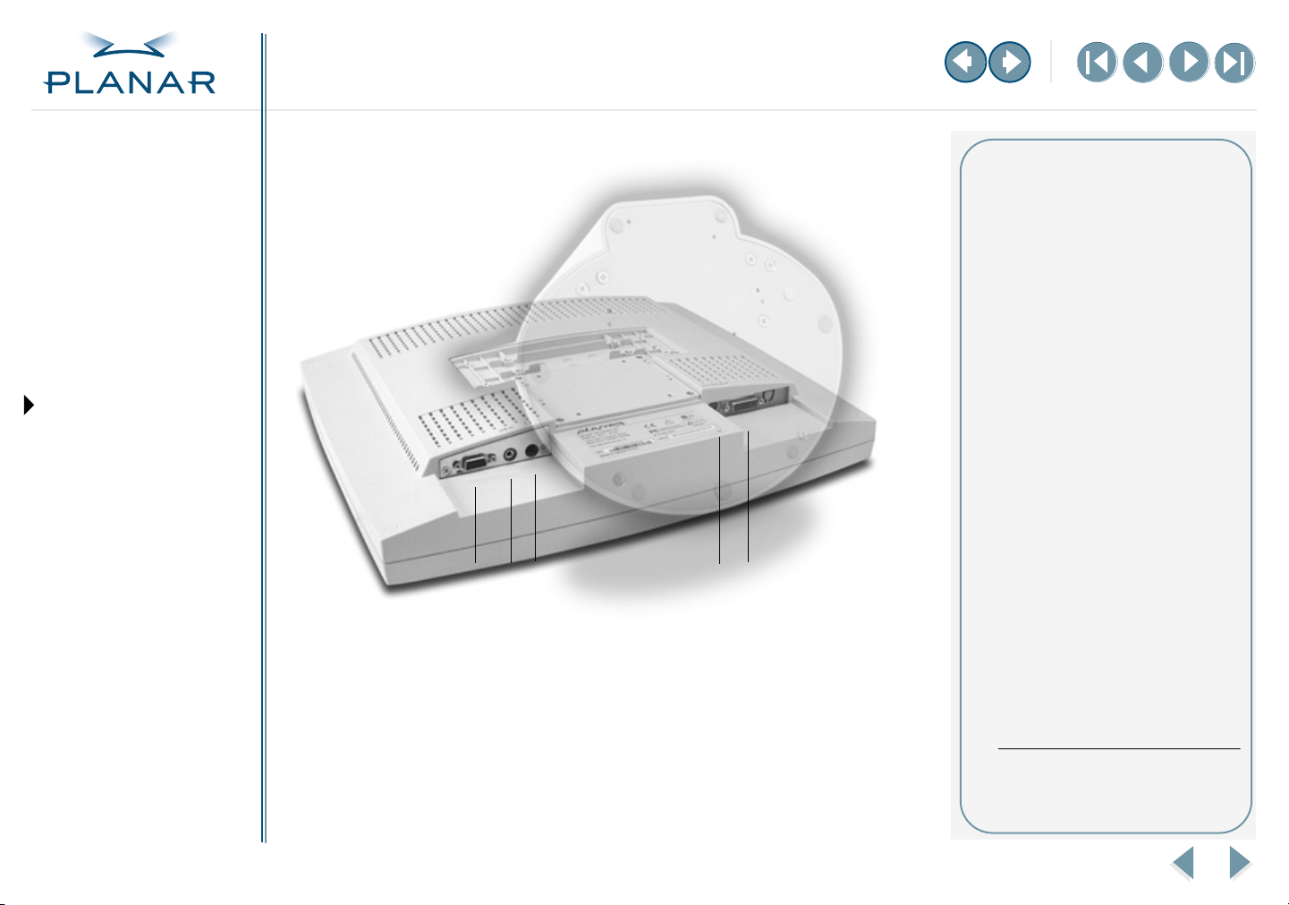
Back panel
Legend
1 Touchscreen port
Port for the RS-232 cable; used
to operate the touch screen.
This cable is provided with the
Optional Touch Screen package.
2 Audio Line In
Jack for the audio cable. (You can
also connect the CD-ROM Line
Out to this jack.)
3 Stereo headphone port
Port for stereo headphones or
powered external speakers.
4 Power input port (locking/
latching mini-DIN 4-pin)
Port for the power connector.
5 VGA connector port
Port for a 2-meter analog or
3
5
412
digital cable. The analog video
cable incorporates a male 29-pin
locking DVI connector at one
end and a male 15-pin D-sub
connector at the other end. The
digital video cable incorporates
a male 29-pin DVI connector at
one end and a male 24-pin DVI
connector at the other end.
*
APPENDIXES
Technical Information
Troubleshooting
VS15 Display
* When the headphones are
plugged in, the stereo speakers are
turned off.
4
Page 13

QUICK LINKS
Contents
Index
Ordering Parts
Product Information
Regulatory Compliance
Warranty
GETTING STARTED
About the Display
Unpack Display
Identify Components
INSTALLING THE DISPLAY
Connect Power
Connect Video
Connect Audio
Connect Touch Screen
Power Management System
USING THE CONTROLS
Display Controls
OSD Menu
Function Menus
OSD Lockout
DDC Change
APPENDIXES
Technical Information
Troubleshooting
Connect the AC Power
You must use the Ault power adapter with this display unit.
1
Plug the AC power cord into the power adapter.
2
Plug the power connector into the locking mini DIN port on the back panel.
Push the connector in until the locking mechanism clicks.
3
Plug the power cord into a grounded wall outlet.
Installation tips
If you need to place your display
face down to attach cables, lower it
carefully on a protective cloth to
protect the screen.
Avoiding power surges
Use a surge protector between the
power adapter and the outlet to
prevent sudden current variations
from reaching the display.
“Unlocking” the power cord
To detach the cord, press down on
the plug housing and then pull out.
IN OPERATION: No power
Check that the display and
computer are both turned on.
Verify that the outlet is functioning.
Plug a lamp into the same outlet
to check.
Check the status of the LED
indicator on the power supply. If the
green light is off, call customer
support for assistance.
Check the status of the LED
indicator on the display. If the
display is on but the green light is
neither steady nor blinking, call
customer support for assistance.
VS15 Display
5
Page 14

QUICK LINKS
Contents
Index
Ordering Parts
Product Information
Regulatory Compliance
Warranty
GETTING STARTED
About the Display
Unpack Display
Identify Components
INSTALLING THE DISPLAY
Connect Power
Connect Video
Connect Audio
Connect Touch Screen
Power Management System
USING THE CONTROLS
Display Controls
OSD Menu
Function Menus
OSD Lockout
DDC Change
Connect the Video Cable
1
Turn off your computer and display before connecting the two units.
2
Plug the video cable into the D-sub VGA connector port on the back panel.
3
Plug the other end of the cable into the VGA port on the computer.
4
Make sure the cable are properly aligned, then tighten the connecting screws
to ensure a secure connection.
5
Turn on the display first and then the computer.
IN OPERATION: Blank screen
Check the LED indicator on the
display. If it is steady green, but you
have no image on the screen, check
that all connections are secure and
the power is on. If the problem still
exists, call customer support for
assistance.
APPENDIXES
Technical Information
Troubleshooting
VS15 Display
6
Page 15

QUICK LINKS
Contents
Index
Ordering Parts
Product Information
Regulatory Compliance
Warranty
GETTING STARTED
About the Display
Unpack Display
Identify Components
INSTALLING THE DISPLAY
Connect Power
Connect Video
Connect Audio
Connect Touch Screen
Power Management System
USING THE CONTROLS
Display Controls
OSD Menu
Function Menus
OSD Lockout
DDC Change
Connect the Audio Cable
1 Plug the audio cable to the Line Out on the audio card in your computer.
2 Plug the other end of the audio cable to the Line In jack on the display.
3 Adjust the volume of the stereo speakers by using the volume control
function on the onscreen display menu.
On volume control
In some instances, the volume
control function may be disabled.
If so, the volume has been preset to
the maximum.
Although the display speakers
are adequate for most audio
applications, Planar does not
recommend using the display
speakers as the exclusive audio
source for medical alarms or
applications critical for audio
performance.
IN OPERATION: No sound
Verify that your display unit has
speakers. Try loading a CD or
another audio program.
Check the volume setting on the
display and the computer. Disable
mute or increase the volume.
Check that the audio cable is
plugged into the OUTPUT on the
computer and INPUT on the display.
Plug headphones or speakers into
your computer to see if they
produce sound.
APPENDIXES
Technical Information
Troubleshooting
VS15 Display
7
Page 16

QUICK LINKS
Contents
Index
Ordering Parts
Product Information
Regulatory Compliance
Warranty
GETTING STARTED
About the Display
Unpack Display
Identify Components
INSTALLING THE DISPLAY
Connect Power
Connect Video
Connect Audio
Connect Touch Screen
Power Management System
USING THE CONTROLS
Display Controls
OSD Menu
Function Menus
OSD Lockout
DDC Change
Connect the Optional Touch Screen
1 Plug the RS232 cable into the RS232 port on the back panel.
2 Plug the other end of the cable to the RS232 serial port on your computer.
3 Load the touchscreen driver from the CD enclosed.
IN OPERATION: No touch
The CD shipped with your display
contains several touchscreen drivers.
Be sure the proper touchscreen
driver is installed on your computer.
If you have conflicts or any problems
with the driver, try reinstalling it.
If you continue to have problems,
then you need to determine the
source, the display or the computer.
Try using the display with another
computer, or installing the driver on
another display.
If the problem still exists, contact
customer support for assistance.
APPENDIXES
Technical Information
Troubleshooting
VS15 Display
8
Page 17

QUICK LINKS
Contents
Index
Ordering Parts
Product Information
Regulatory Compliance
Warranty
GETTING STARTED
About the Display
Unpack Display
Identify Components
INSTALLING THE DISPLAY
Connect Power
Connect Video
Connect Audio
Connect Touch Screen
Power Management System
USING THE CONTROLS
Display Controls
OSD Menu
Function Menus
OSD Lockout
DDC Change
Power Management System
The VS15 display complies with the VESA DPMS standard. This standard provides
four power-saving modes, based on the display detecting the horizontal or vertical
sync signal. This table describes the four modes.
AC Input Power
Mode
ON with audio
without audio
Standby 5 watts maximum Blinking green
Suspend 5 watts maximum Blinking green
OFF 5 watts maximum OFF
When the display is in power-saving mode, or when it detects an incorrect timing,
the display screen goes blank and the power LED indicator blinks.
(including AC adapter) LED Status
40 watts maximum
37 watts maximum
Steady green
Steady green
APPENDIXES
Technical Information
Troubleshooting
VS15 Display
9
Page 18

QUICK LINKS
Contents
Index
Ordering Parts
Product Information
Regulatory Compliance
Warranty
GETTING STARTED
About the Display
Unpack Display
Identify Components
INSTALLING THE DISPLAY
Connect Power
Connect Video
Connect Audio
Connect Touch Screen
Power Management System
USING THE CONTROLS
Display Controls
OSD Menu
Function Menus
OSD Lockout
DDC Change
Display Controls
The VS15 display features an intuitive, menu-driven, onscreen display. Use the
OSD menu to adjust the contrast, brightness, display position, color temperature,
stereo speaker volume, and set the OSD parameters.
Use the push buttons on the front of the display to adjust the controls. Access the
OSD menu with a quick press to the OSD/Function UP button when the display is
powered-up. If your computer is in power-saving mode, or is powered-down, the
OSD menu is inaccessible.
1
2
3, 4
Legend
1 Function UP and DOWN buttons
Function UP activates the OSD
menu and navigates the main
menu. Function DOWN navigates
the submenu.
2 Adjust PLUS and MINUS buttons
Increase or decrease the value of
the selected function. Each button
also serves a Function ENTER
button.
3 Power switch
Turns the display ON or OFF
when pressed for a minimum of
2 seconds.
4 LED power indicator
Is lit continuously when the
display is on; blinks when the
display is in power-saving mode.
APPENDIXES
Technical Information
Troubleshooting
VS15 Display
10
Page 19

QUICK LINKS
Contents
Index
Ordering Parts
Product Information
Regulatory Compliance
Warranty
GETTING STARTED
About the Display
Unpack Display
Identify Components
INSTALLING THE DISPLAY
Connect Power
Connect Video
Connect Audio
Connect Touch Screen
Power Management System
USING THE CONTROLS
Display Controls
OSD Menu
Function Menus
OSD Lockout
DDC Change
APPENDIXES
Technical Information
Troubleshooting
Onscreen Display Main Menu
The available control functions of the onscreen display are grouped into categories.
The display’s selected mode of operation (either analog or digital) determines the
available categories.
Onscreen Display Menu
Analog operation
Basic Change brightness, contrast and view
DDC mode.
Position Change the display position.
Miscellaneous Adjust OSD position and display
information about the monitor.
Color Adjust the color settings.
Digital operation
Digital Basic Change brightness, contrast and view
DDC mode.
Miscellaneous Adjust OSD position and display
information about the monitor.
VS15 Display
11
Page 20

QUICK LINKS
Contents
Index
Ordering Parts
Product Information
Regulatory Compliance
Warranty
GETTING STARTED
About the Display
Unpack Display
Identify Components
INSTALLING THE DISPLAY
Connect Power
Connect Video
Connect Audio
Connect Touch Screen
Power Management System
USING THE CONTROLS
Display Controls
OSD Menu
Function Menus
OSD Lockout
DDC Change
APPENDIXES
Technical Information
Troubleshooting
Function Menus
The following tables describe the items of each OSD menu.
Basic Menu
Contrast Adjust the contrast level of the display.
Brightness Adjust the brightness of the
display backlight.
Volume Adjust the audio volume.
DDC Digital/analog DDC mode
(information only).
MORE
VS15 Display
12
Page 21

QUICK LINKS
Contents
Index
Ordering Parts
Product Information
Regulatory Compliance
Warranty
GETTING STARTED
About the Display
Unpack Display
Identify Components
INSTALLING THE DISPLAY
Connect Power
Connect Video
Connect Audio
Connect Touch Screen
Power Management System
USING THE CONTROLS
Display Controls
OSD Menu
Function Menus
OSD Lockout
DDC Change
Position Menu
Auto Adjust Automatically adjust the picture quality and alignment.
(Use this function in Windows or similar environments.
Not available in the interlaced modes of operation.)
Phase Adjust the screen display for focus and clarity.
Clock Adjust the display pixel alignment.
H-Position Adjust the display position horizontally.
V-Position Adjust the display position vertically.
Graph/Text Select Graph or Text expansion method while 640 x 400
or 720 x 400 mode. (Not available in all modes.)
APPENDIXES
Technical Information
Troubleshooting
VS15 Display
Reset Reset all the parameters of this menu.
MORE
13
Page 22

QUICK LINKS
Contents
Index
Ordering Parts
Product Information
Regulatory Compliance
Warranty
GETTING STARTED
About the Display
Unpack Display
Identify Components
INSTALLING THE DISPLAY
Connect Power
Connect Video
Connect Audio
Connect Touch Screen
Power Management System
USING THE CONTROLS
Display Controls
OSD Menu
Function Menus
OSD Lockout
DDC Change
Miscellaneous Menu
H-Position Adjust the onscreen display position horizontally.
V-Position Adjust the onscreen display position vertically.
Menu Timer Adjust the length of idle time before the menu
display turns off (5, 10, 15, 20, 25, 30 seconds).
Information Display the incoming display mode and
firmware version.
Language Choose the appropriate language: English, French,
German, Italian, or Spanish.
APPENDIXES
Technical Information
Troubleshooting
VS15 Display
Reset Reset all the parameters of this menu.
MORE
14
Page 23

QUICK LINKS
Contents
Index
Ordering Parts
Product Information
Regulatory Compliance
Warranty
GETTING STARTED
About the Display
Unpack Display
Identify Components
Color Menu
*
INSTALLING THE DISPLAY
Connect Power
Connect Video
Connect Audio
Connect Touch Screen
Power Management System
USING THE CONTROLS
Display Controls
OSD Menu
Function Menus
OSD Lockout
DDC Change
APPENDIXES
Technical Information
Troubleshooting
COLOR 9300 Set the color temperature of white to 9300° Kelvin
COLOR 6500 Set the color temperature of white to 6500° Kelvin
COLOR USER Enable “User Color” selection, and adjust individual RGB levels
RAdjust red contrast
GAdjust green contrast
BAdjust blue contrast
*There are three sets of color temperature settings available: two for standard settings and
one for user adjustment.
VS15 Display
MORE
15
Page 24

QUICK LINKS
Contents
Index
Ordering Parts
Product Information
Regulatory Compliance
Warranty
GETTING STARTED
About the Display
Unpack Display
Identify Components
Digital Basic Menu
INSTALLING THE DISPLAY
Connect Power
Connect Video
Connect Audio
Connect Touch Screen
Power Management System
USING THE CONTROLS
Display Controls
OSD Menu
Function Menus
OSD Lockout
DDC Change
APPENDIXES
Technical Information
Troubleshooting
VS15 Display
Contrast Adjust the contrast level of the display.
Brightness Adjust the brightness of the display backlight.
Volume Adjust the audio volume.
DDC Digital/analog DDC mode
(information only).
MORE
16
Page 25

QUICK LINKS
Contents
Index
Ordering Parts
Product Information
Regulatory Compliance
Warranty
GETTING STARTED
About the Display
Unpack Display
Identify Components
INSTALLING THE DISPLAY
Connect Power
Connect Video
Connect Audio
Connect Touch Screen
Power Management System
USING THE CONTROLS
Display Controls
OSD Menu
Function Menus
OSD Lockout
DDC Change
Digital Miscellaneous Menu
H-Position Adjust the onscreen display position
horizontally.
V-Position Adjust the onscreen display position vertically.
Menu Timer Adjust the length of idle time before the menu
display turns off (5, 10, 15, 20, 25, 30 seconds).
Information Display the incoming display mode and
firmware version.
Language Choose the appropriate language: English,
French, German, Italian, or Spanish.
APPENDIXES
Technical Information
Troubleshooting
VS15 Display
Reset Reset all the parameters of this menu.
17
Page 26

QUICK LINKS
Contents
Index
Ordering Parts
Product Information
Regulatory Compliance
Warranty
GETTING STARTED
About the Display
Unpack Display
Identify Components
INSTALLING THE DISPLAY
Connect Power
Connect Video
Connect Audio
Connect Touch Screen
Power Management System
USING THE CONTROLS
Display Controls
OSD Menu
Function Menus
OSD Lockout
DDC Change
Onscreen Display Lockout
The display incorporates an OSD lockout function. Pressing controls
Function DOWN, Adjust PLUS, and Adjust MINUS—that is, buttons 2, 3, and 4—
simultaneously lock out the onscreen display. Display settings cannot be altered at
this point, but navigation through the OSD menus is possible. An “OSD” lock
appears at the bottom of the OSD menu. To unlock the onscreen display, press the
same three controls in the same manner as if locking the display.
APPENDIXES
Technical Information
Troubleshooting
VS15 Display
18
Page 27

QUICK LINKS
Contents
Index
Ordering Parts
Product Information
Regulatory Compliance
Warranty
GETTING STARTED
About the Display
Unpack Display
Identify Components
INSTALLING THE DISPLAY
Connect Power
Connect Video
Connect Audio
Connect Touch Screen
Power Management System
USING THE CONTROLS
Display Controls
OSD Menu
Function Menus
OSD Lockout
DDC Change
APPENDIXES
Technical Information
Troubleshooting
DDC Change
Follow these instructions to change the display from analog to digital mode or
from digital to analog mode.
1 Make sure the display power is ON. (The LED indicator is steady or blinking).
2 Disconnect video cable from the display. The display indicates “No Video.”
3 Wait for the “No Video” message to disappear.
4 Push the Function UP ( ) and Adjust MINUS ( ) buttons simultaneously.
This creates a change in the DDC file; one of the following messages appears.
The message on the left indicates a change from analog to digital mode.
The message on the right indicates a change from digital to analog mode.
5 Plug the video cable into the display. The display shows the supplied
video input.
VS15 Display
19
Page 28

QUICK LINKS
Contents
Index
Ordering Parts
Product Information
Regulatory Compliance
Warranty
GETTING STARTED
About the Display
Unpack Display
Identify Components
INSTALLING THE DISPLAY
Connect Power
Connect Video
Connect Audio
Connect Touch Screen
Power Management System
USING THE CONTROLS
Display Controls
OSD Menu
Function Menus
OSD Lockout
DDC Change
APPENDIXES
Technical Information
Troubleshooting
Technical Information
VS15XAD/VS15XAD-TR Specification
Display panel 381 mm (15-in.) XGA active-matrix color TFT LCD
Display color 262,144 colors
Dimension (mm) 408 x 333 x 85 (W x H x D)
Weight (kg) 5 kg
Display area (mm) 304.1 x 228.1 (W x H); 380.1 mm (15-in.) diagonal
Response time (ms) 30 ms ON and 25 ms OFF maximum
Viewing angle ±80 degrees typical (horizontal or vertical)
Contrast ratio 400:1 typical
Brightness Non-touch
Resistive touch
Pixel pitch (mm) 0.297 (W) x 0.297 (H)
Reliability Monitor
Backlight
Video interface 15.4 M, 8 bit
Scanning frequency Analog
Digital
Power consumption 40 watts maximum; <5 watts in standby or off mode
Power adapter, Ault
Input power
Audio Stereo speakers
Stereo headphone jack output Output power 1 watt at 8 ohms
Temperature Operating
Nonoperating
Humidity Operating
Nonoperating
Altitude Operating
Nonoperating
Shock 50 g, 11 ms duration operating/nonoperating
Regulatory See Regulatory Compliance
228 cd/m2 typical
200 cd/m2 typical
40,000 hours mean time between failure (MTBF)
50,000 hours to reach 50% of initial brightness
Horizontal: 24 to 62 kHz; Vertical: 50 to 90 Hz
Horizontal: 30 to 64 kHz; Vertical: 56 to 85 Hz
12 volts / 3.5 amps, 40 watts
100 volts AC to 240 volts AC at 50 to 60 Hz, AC Adapter (external)
1 watt amplifier
Maximum input levels
Input impedance
0° to 40° C
-20° to 65° C
10% to 93% relative humidity noncondensing
0% to 95% relative humidity noncondensing
0 to 3500 m
0 to 1220 m
(Half sine with three shocks on each of six axes)
1 volt RMS typical
2000 ohms typical
VS15 Display
20
Page 29

QUICK LINKS
Contents
Index
Ordering Parts
Product Information
Regulatory Compliance
Warranty
GETTING STARTED
About the Display
Unpack Display
Identify Components
INSTALLING THE DISPLAY
Connect Power
Connect Video
Connect Audio
Connect Touch Screen
Power Management System
USING THE CONTROLS
Display Controls
OSD Menu
Function Menus
OSD Lockout
DDC Change
APPENDIXES
Technical Information
Troubleshooting
Troubleshooting
Problem: Display indicates “No Video”
When the display is powered-on and no video signal is being received, the No Video message
appears until the display enters power-saving mode.
Solution: Ensure that the video cable is connected to the user system and the display.
Problem: No image on screen
Solution: To produce an image on the LCD screen, follow these steps:
1 Make sure that the power indicator on the display is illuminated, all connections are secure,
and the system is running on a supported video timing mode.
2 If the power LED is not lit, secure the AC power connector. If the AC adapter has an LED,
verify that the LED is illuminated. If it is not, speak with customer support.
3 Turn the display off and then turn it back on.
4 If one is available, connect your system to another VS15 display. If the system functions
properly with the alternate display, but not with the VS15XAD display, and the VS15XAD
display’s power LED is blinking, the output timing of the computer’s video board may be out
of the display’s synchronous range. Change to an alternate mode that is listed in Appendix A
or connect to an alternate video source and repeat steps 1 and 2.
5 Ensure that the computer’s video port is enabled. This is a function of the video board in the
user computer system. Refer to the video board documentation for instructions on how to
enable the video port.
6 If the system does not function with either the alternate display or the VS15XAD display, get
help from technical support.
VS15 Display
21
Page 30

QUICK LINKS
Contents
Index
Ordering Parts
Product Information
Regulatory Compliance
Warranty
GETTING STARTED
About the Display
Unpack Display
Identify Components
INSTALLING THE DISPLAY
Connect Power
Connect Video
Connect Audio
Connect Touch Screen
Power Management System
USING THE CONTROLS
Display Controls
OSD Menu
Function Menus
OSD Lockout
DDC Change
Index
A
AC power, connecting 5
Adjust button
adjusting display
analog-to-digital mode
audio
cable
line
B
back panel 4
Basic menu
C
cable
audio
audio line-in port, connecting
touchscreen
video analog
video digital
video input
cleaning instructions
Color menu
components, identifying
3, 10
10
2
4
12
2
2
2
2
4
vii
15
19
connecting
AC power
stereo speakers
touch screen
video cable
connector ports
controls, display
5
7
8
6
4
10
D
DDC change 19
desk stand
Digital Basic menu
Digital Miscellaneous menu
digital-to-analog mode
display
4
3
3
16
adjusting
back panel
cleaning
controls, menu
front panel
installing
setup
troubleshooting
unpacking
10
4
vii
3
5
2
2
17
19
10
21
disposal information
DPMS
9
F
front panel 3
Function buttons
I
identifying components 3
information
disposal
ordering parts
product
technical
installing display
L
LCD screen 3
cleaning
troubleshooting
vii
3, 10
vii
27
vi
20
5
vii
21
APPENDIXES
Technical Information
Troubleshooting
VS15 Display
22
Page 31

QUICK LINKS
Contents
Index
Ordering Parts
Product Information
Regulatory Compliance
Warranty
GETTING STARTED
About the Display
Unpack Display
Identify Components
INSTALLING THE DISPLAY
Connect Power
Connect Video
Connect Audio
Connect Touch Screen
Power Management System
USING THE CONTROLS
Display Controls
OSD Menu
Function Menus
OSD Lockout
DDC Change
M
menu
analog operation
Basic
12
Color
15
Digital Basic
Digital Miscellaneous
digital operation
function
main, onscreen display
Miscellaneous
Position
Miscellaneous menu
16
12
13
O
onscreen display
analog operation
digital operation
lockout
18
main menu
ordering parts
11
27
14
11
14
11
11
11
17
11
P
ports, connector 4
Position menu
power
connecting AC
indicator
input port
management system
ON indicator
switch
product information
13
10
4
3
3, 10
R
repair 24
RS232 connector
4
S
safety instructions vi
selecting workspace
stereo speakers
headphone port
3, 7
T
technical information 20
touch screen
cable
2
5
9
cleaning
connecting
port
troubleshooting
vii
4
8
21
U
vi
2
unpacking display 2
V
VESA DPMS 9
video
analog cable
cable, connecting
digital cable
input port
2
2
4
6
W
4
warranty 24
workspace, selecting
2
APPENDIXES
Technical Information
Troubleshooting
VS15 Display
23
Page 32

QUICK LINKS
Contents
Index
Ordering Parts
Product Information
Regulatory Compliance
Warranty
GETTING STARTED
About the Display
Unpack Display
Identify Components
INSTALLING THE DISPLAY
Connect Power
Connect Video
Connect Audio
Connect Touch Screen
Power Management System
USING THE CONTROLS
Display Controls
OSD Menu
Function Menus
OSD Lockout
DDC Change
APPENDIXES
Technical Information
Troubleshooting
Overview of Standard Warranty
Summary
• Standard 1-year “repair and return” warranty on all VS15 displays
• Typical repair turnaround time of 10 business days
• Repair facilities and technical support in the United States and in Europe
Standard Warranty Return Procedure
As a Planar Standard Warranty customer, you must follow the procedure below if you have
a non-functioning display. Planar customer service staff will attempt to correct any minor
issues that may be causing the problem. Once Planar has determined that you have a nonfunctioning product, Planar will arrange for return and repair of the non-functioning product.
1 Contact Planar via the web at http://www.planar.com/support. In North America, call
(866) PLANAR1 (866.752.6271). In Europe, call +358 9 420 01 or send your info by fax
to +358 9 420 0200. You must have the model number, serial number, and proof-ofpurchase available.
2 Planar customer service staff will attempt to correct any minor issues that may be
causing the problem. If we are unable to correct the problem to your satisfaction,
we will issue a Return Material Authorization (RMA).
3 You must return the product, as specified, to Planar Systems. Do not return the
battery cell or cart to planar Systems unless directed by Planar customer service.
4 Planar will validate the defect, repair the unit, and return the unit to you. The typical
turnaround time is 10 business days.
At its sole discretion, Planar may charge you the customer for returned units deemed
functional or for returned units with only customer-caused damage. It is the responsibility of
the customer to properly package the hardware, include all appropriate materials, and return
it to the location specified by Planar customer service.
MORE
VS15 Display
24
Page 33

QUICK LINKS
Contents
Index
Ordering Parts
Product Information
Regulatory Compliance
Warranty
GETTING STARTED
About the Display
Unpack Display
Identify Components
INSTALLING THE DISPLAY
Connect Power
Connect Video
Connect Audio
Connect Touch Screen
Power Management System
USING THE CONTROLS
Display Controls
OSD Menu
Function Menus
OSD Lockout
DDC Change
Summary Limitations and Exclusions of VS15 Displays
1 Warranty is valid only for the first consumer purchaser (non-transferable).
2 Warranty does not cover the battery cell(s), mouse, or keyboard.
3 The customer must provide original proofs of purchase for the hardware.
4 Warranty is void on any product with a defaced, modified, or removed serial number.
5 Warranty is void on any product with damage, deterioration, or malfunction resulting
from the following:
a) Accident, misuse, neglect, fire, water, lightning, or other acts of nature, unauthorized
product modification, or failure to follow instructions supplied with the product.
b) Repair or attempted repair by anyone not authorized by Planar.
c) Any damage of the product due to shipment.
d) Removal or installation of the product.
e) Causes external to the product, such as electric power fluctuations or failure.
f) Use of supplies or parts not meeting Planar specifications.
g) Normal wear and tear, including backlights dimming over time.
h) Any other cause which does not relate to a product defect.
6 Warranty excludes removal, installation, and setup service charges.
Limitation of Implied Warranties
THERE ARE NO WARRANTIES, EXPRESS OR IMPLIED, WHICH EXTEND BEYOND THE
DESCRIPTION CONTAINED HEREIN INCLUDING THE IMPLIED WARRANTY OF
MERCHANTABILITY AND FITNESS FOR A PARTICULAR PURPOSE.
MORE
APPENDIXES
Technical Information
Troubleshooting
VS15 Display
25
Page 34

QUICK LINKS
Contents
Index
Ordering Parts
Product Information
Regulatory Compliance
Warranty
GETTING STARTED
About the Display
Unpack Display
Identify Components
INSTALLING THE DISPLAY
Connect Power
Connect Video
Connect Audio
Connect Touch Screen
Power Management System
USING THE CONTROLS
Display Controls
OSD Menu
Function Menus
OSD Lockout
DDC Change
Exclusion of Damages
THE LIABILITY OF PLANAR IS LIMITED TO THE COST OF REPAIR OR REPLACEMENT OF
THE PRODUCT. PLANAR SHALL NOT BE LIABLE FOR THE FOLLOWING:
1 DAMAGE TO OTHER PROPERTY CAUSED BY ANY DEFECTS IN THE PRODUCT,
DAMAGES BASED UPON INCONVENIENCE, LOSS OF USE OF THE PRODUCT, LOSS
OF TIME, LOSS OF PROFITS, LOSS OF BUSINESS OPPORTUNITY, LOSS OF GOODWILL,
INTERFERENCE WITH BUSINESS RELATIONSHIPS, OR OTHER COMMERCIAL LOSS,
EVEN IF ADVISED OF THEIR POSSIBILITY OF SUCH DAMAGES.
2 ANY OTHER DAMAGES, WHETHER INCIDENTAL, INDIRECT, CONSEQUENTIAL, OR
OTHERWISE.
3 ANY CLAIM AGAINST THE CUSTOMER BY ANY OTHER PARTY.
Effect of Local Law
This warranty gives you specific legal rights, and you may have other rights, which vary from
locality to locality. Some localities do not allow limitations on implied warranties and/or do
not allow the exclusion of incidental or consequential damages, so the above limitations and
exclusions may not apply to you.
APPENDIXES
Technical Information
Troubleshooting
VS15 Display
26
Page 35

QUICK LINKS
Contents
Index
Ordering Parts
Product Information
Regulatory Compliance
Warranty
GETTING STARTED
About the Display
Unpack Display
Identify Components
INSTALLING THE DISPLAY
Connect Power
Connect Video
Connect Audio
Connect Touch Screen
Power Management System
USING THE CONTROLS
Display Controls
OSD Menu
Function Menus
OSD Lockout
DDC Change
Ordering Information
Non-touch display
VS15XAD Display Part Number
VS15XAD 15-inch XGA Medically Certified Display with desk stand
and US power cord (non-touch)
VS15XAD 15-inch XGA Medically Certified Display with desk stand
and European power cord (non-touch)
VS15XAD 15-inch XGA Medically Certified Display with universal
mounting plate and US power cord (non-touch)
VS15XAD 15-inch XGA Medically Certified Display with universal
mounting plate and European power cord (non-touch)
Cable & Power Adapter Part Number
Cable, DVI-VGA, 2 m, white, smooth surface 903-0227-00
Cable, DVI-DVI, 2 m, white, smooth surface 903-0204-00
Audio cable, 1.5 m 903-0168-00
Power adapter 903-0013-01
996-0475-00
996-0475-01
996-0475-02
996-0475-03
APPENDIXES
Technical Information
Troubleshooting
VS15 Display
MORE
27
Page 36

QUICK LINKS
Contents
Index
Ordering Parts
Product Information
Regulatory Compliance
Warranty
GETTING STARTED
About the Display
Unpack Display
Identify Components
INSTALLING THE DISPLAY
Connect Power
Connect Video
Connect Audio
Connect Touch Screen
Power Management System
USING THE CONTROLS
Display Controls
OSD Menu
Function Menus
OSD Lockout
DDC Change
Resistive-touch display
VS15XAD-TR Display Part Number
VS15XAD-TR 15-inch XGA Medically Certified Display with desk
stand and US power cord (resistive touch)
VS15XAD-TR 15-inch XGA Medically Certified Display with desk
stand and European power cord (resistive touch)
VS15XAD-TR 15-inch XGA Medically Certified Display with
universal mounting plate and US power cord (resistive touch)
VS15XAD-TR 15-inch XGA Medically Certified Display with
universal mounting plate and European power cord
(resistive touch)
Cable & Power Adapter Part Number
Touchscreen cable, 2 m, white, smooth surface 903-0233-00
Power adapter, Ault 903-0013-01
996-0476-00
996-0476-01
996-0476-02
996-0476-03
MORE
APPENDIXES
Technical Information
Troubleshooting
VS15 Display
28
Page 37

QUICK LINKS
Contents
Index
Ordering Parts
Product Information
Regulatory Compliance
Warranty
GETTING STARTED
About the Display
Unpack Display
Identify Components
INSTALLING THE DISPLAY
Connect Power
Connect Video
Connect Audio
Connect Touch Screen
Power Management System
Cables and accessories
Miscellaneous Part Number
Cable, DVI-VGA, 3 m, white, smooth surface 903-0228-00
Cable, DVI-VGA, 3 m, black, smooth surface 903-0229-00
Cable, DVI-VGA, 10 m, white, smooth surface 903-0230-00
Cable, DVI-DVI, 3 m, white, smooth surface 903-0231-00
Cable, DVI-DVI, 10 m, white, smooth surface 903-0232-00
European medical grade power cord, 3 m 903-0251-00
US medical grade power cord, 3 m 903-0169-00
Touchscreen cable, 3 m, white, smooth surface 903-0234-00
Touchscreen cable, 10 m, white, smooth surface 903-0235-00
Universal mounting plate 501-0301-00
USING THE CONTROLS
Display Controls
OSD Menu
Function Menus
OSD Lockout
DDC Change
APPENDIXES
Technical Information
Troubleshooting
Planar desk stand 501-0348-00
VS15 Display
29
 Loading...