

Page 1
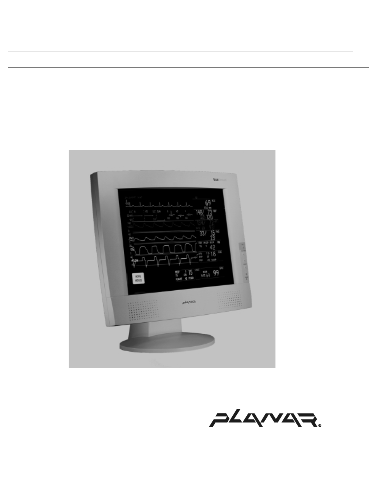
VS15XAD
ONITOR FAMILY
M
ITALSCREEN
V
Operations Manual
EDICAL GRADE
M
Page 2

Planar Systems, Inc. © 2001
“Planar” is a registered trademark of Planar Systems, Inc.
This document is subject to change without notice. Planar provides this information as reference
only. Reference to other vendors’ products does not imply any recommendation or endorsement.
Revision Control
Date Description
May 2001 Document number OM705-00 (020-0158-00 Rev. A)
Page 3

Contents
Planar VS15XAD VitalScreen Medical Grade Monitor Family.....................1
Cleaning Instructions ...................................................................................................2
Safety Instructions........................................................................................................2
Disposal Information....................................................................................................3
Regulatory Compliance................................................................................................3
European Union Declaration of Conformity for Medical Applications...............4
Symbol Explanations ...................................................................................................5
Product Contents and Installation .....................................................................6
Identifying Components...............................................................................................7
Front View............................................................................................................7
Rear View .............................................................................................................8
Connecting AC Power..................................................................................................9
Connecting Video........................................................................................................9
Connecting Optional Stereo Speakers........................................................................10
Connecting the Optional Touchscreen.......................................................................11
Power Management System.......................................................................................11
Using the On-Screen Display.....................................................................................12
OSD Main Menu........................................................................................................12
Function Menus..........................................................................................................12
Basic Menu...............................................................................................13
Position Menu ..........................................................................................13
Miscellaneous Menu.................................................................................14
Color Menu ..............................................................................................14
Digital Basic Menu ..................................................................................15
Digital Miscellaneous Menu ....................................................................15
On-Screen Display Lockout.......................................................................................16
DDC Change (Analog to Digital Mode or Digital to Analog Mode).........................16
Technical Information.......................................................................................17
VS15XAD VitalScreen Medical Grade Monitor Family Specifications....................17
Troubleshooting Procedures.............................................................................18
PROBLEM: Display Indicates “No Video”........................................................18
PROBLEM: No Image on Monitor.....................................................................18
Description of Warranty...................................................................................19
Commencement and Duration of Warranty........................................................19
Place of Repair or Replacement.........................................................................19
Limitation of Warranty.......................................................................................19
Installation..........................................................................................................20
Technical Assistance...........................................................................................20
Repair Service.....................................................................................................20
Ordering Information .......................................................................................21
Operations Manual (OM705-00)
i
Page 4

Figures
Figure 1: Controls and Front View....................................................................7
Figure 2: Monitor, Rear Ports............................................................................8
Figure 3: Connecting Power to the Monitor .....................................................9
Figure 4: Connecting the Monitor to Your System..........................................9
Figure 5: Connecting the Stereo Speakers ......................................................10
Figure 6: Connecting the Optional Touchscreen Cable.................................11
Figure 7. Basic Menu.........................................................................................13
Figure 8. Position Menu ....................................................................................13
Figure 9. Miscellaneous Menu..........................................................................14
Figure 10. Color Menu ......................................................................................14
Figure 11. Digital Basic Menu ..........................................................................15
Figure 12. Digital Miscellaneous Menu ...........................................................15
ii
Operations Manual (OM705-00)
Page 5

Planar VS15XAD VitalScreen Medical Grade
Monitor Family
The Planar VS15XAD VitalScreen Medical Grade Monitor family is a set of
high-resolution color monitors designed to be versatile and easy to use. These
monitors can accept either analog or digital video input and display most video
standards from 640 x 480 (Video Graphics Array, or VGA, standard) to
1024 x 768 (Extended Graphics Array, or XGA, standard). The controls located
on the front panel allow you to easily adjust the monitor’s display parameters
using on-screen display (OSD) menus.
The monitor’s video input is a single-link, transition minimized differential
signaling (TMDS) digital visual interface (DVI) and is compliant with the
Digital Display Working Group (DDWG) DVI standard. This interface produces
the sharpest display image possible with little need for adjustment. Setup is
simple: just plug in the monitor and use.
The monitor uses a mounting plate that conforms to the Video Electronics
Standards Association (VESA) mounting standard
1
. That configuration allows
the monitor to be mounted in a variety of ways, such as on a wall bracket or
swing arm. An alternate configuration with a desk stand is also available for easy
use on flat work surfaces.
The architecture of the Planar VS15XAD VitalScreen Medical Grade Monitor
incorporates an active matrix liquid-crystal display (AMLCD) panel that
produces a clear display with low radiation emission, greatly reducing the
radiation-related health concerns associated with cathode-ray tube monitors.
1
The VESA Flat Panel Monitor Physical Mounting Interface (FPMPMI) Standard defines
physical mounting interfaces for flat panel monitors, corresponding standards for flat
panel monitor mounting devices and associated cable, cable connectors and power supply
location guidelines. For more information, see http://www.vesa.org/
Operations Manual (OM705-00)
.
1
Page 6

Cleaning Instructions
The VS15XAD VitalScreen Medical Grade Monitor will continue to operate
normally while being cleaned in a fashion normal for a hospital environment.
That includes cleaning with a damp (wrung out), mild soapy cloth. Drip
protection is provided in accordance with IPX1 rating defined in the
IEC/EN60529 standard.
The VS15XAD VitalScreen Medical Grade Monitor family withstands
nonabrasive cloths and cleaning solutions used in hospitals for like equipment.
That would typically include warm water and mild detergent for all surfaces or
70 percent isopropyl alcohol for the touch-screen surface. Possible cleaning
solutions include these:
70 percent isopropyl alcohol
•
1.6 percent aqueous ammonia
•
Cidex® (2.4 percent glutaraldehyde solution)
•
Sodium hypochlorite (bleach) 10 percent
•
“Green soap” United States Pharmacopoeia
•
0.5 percent Chlorhexidine in 70 percent isopropyl alcohol
•
Ovation®
•
Formula 409®
•
Fantastic®
•
•
WexCide
To clean the screen, do not spray liquid cleaners directly onto it. Stand away from the
monitor and spray the cleaning solution onto a nonabrasive cloth. Without applying
excessive pressure, clean the screen with the slightly dampened cloth.
®
863
Safety Instructions
•
Do not place the monitor near a window. Exposing the monitor to rain, water,
moisture or constant direct sunlight can severely damage it.
•
Do not place anything on top of the monitor-to-computer signal cord. Make sure the
cord is placed where it will not be stepped on.
•
Do not apply excessive pressure to the screen. Excessive pressure may cause
permanent damage to the display.
•
The monitor and power supply units have no user-serviceable parts inside, except
for the backlight lamp assemblies. Refer all servicing to qualified personnel to
maintain your warranty.
•
Do not cover or obstruct the venting holes on the back of the monitor.
Store the monitor within -20° to +65° Celsius. Storing your monitor outside
•
that temperature range could result in permanent damage. Please store the
monitor in its original shipping carton.
•
If any cord or cable is frayed or damaged, immediately replace it with another of the
same type and rating as supplied by Planar. See “Ordering Information” on page 22
for part numbers. The safety and regulatory listings and certifications are based on
the cable supplied by Planar.
•
If the monitor has been exposed to liquid, it has been dropped, or if its case has been
damaged, it may pose a shock or fire hazard; immediately unplug it and contact
customer service for assistance.
2
Operations Manual (OM705-00)
Page 7

Use only the power adapter that has been tested and approved for use with
•
this monitor product. See “Ordering Information” on
numbers.
Caution: The power adapter must be plugged into a GROUNDED
power outlet.
To clean the power adapter, use a cloth dampened with liquid cleaner on the
•
outside of the enclosure and cable only. Do not immerse the product in liquid,
or a safety hazard could arise during use.
page
22 for part
Do not use the power adapter near flammable anesthetics.
•
Disposal Information
This monitor contains cold cathode fluorescent lamps, which contain a maximum
of 12 milligram (3 milligram per lamp) of mercury. Please follow local
ordinances or regulations for its disposal.
Regulatory Compliance
This monitor has been tested and found to comply with IEC/EN 60601-1 and
IEC/EN 60601-1-2 standards by TÜV Rheinland and is certified by CSA
International to meet medical standard C22.2 No. 601.1-M1990 (C US Mark).
Because many medical offices are located in residential areas, the medical
monitor, in addition to meeting medical requirements, has also been tested and
found to comply with the limits for Federal Communications CommissionFCC)
Class B computing devices in a typically configured system. It is the system
integrator or configurer’s responsibility to test and ensure that the entire system
complies with applicable electromagnetic compatibility (EMC) laws.
Planar Systems, Inc. has made great efforts to support the medical device
industry, in particular medical device manufacturers and medical device system
integrators. We offer state-of-the-art color displays that are compliant with
worldwide accepted medical device safety standards, and for the European
market, CE-marked displays based on compliance with counsel directive
93/42/EEC—commonly referred to as the Medical Device Directive (MDD).
The following summarizes our qualification of these displays as it relates to
compliance with the MDD.
The European Medical Device Directive requires that the intended use of the
device be defined. The intended use of these displays is “to display
alphanumeric, graphic and image data as inputted from any type of medical
device.” These displays do not provide a measurement function in any way, and
it is the device and systems manufacturers responsibility to verify its function in
the integrated device or system.
The display was classified as required by the MDD according to Annex IX of the
directive and the medical device (MEDDEV) guidance available at the time of
classification. Because the display uses electrical energy and has no direct
patient connections and—by itself—no medical utility, the display is classified
according to Rule 12 as an MDD Class I device–component or accessory. The
MDD states that manufacturers of Class I medical devices or accessories shall
satisfy the requirements in regard to design and manufacturing controls, i.e., the
applicable assessment route to be used for CE-marking under the MDD, and it
shall carry the CE-mark according to Annex XII of the directive, with no notified
body annotation.
Operations Manual (OM705-00)
3
Page 8

The applicable safety standards for an MDD Class I display are IEC/EN 606011: 1990 along with Amendments 1 and 2. To help the medical device designer
evaluate the suitability of these displays, Planar has also conducted EMC testing
to IEC 60601-1-2 as it can be applied. The display with its power supply alone
does not represent a functional medical device. Hence, Planar configured a
minimal operating system to exercise the display. The resulting data is made
available to interested parties.
The data is informative data, not certification data. Certification data must be
obtained by the device or system integrator according to Article 12 of the MDD
titled “Particular procedure for systems and procedure packs.” Paragraph 2
clearly outlines the device or system integrator’s responsibility in this matter.
In summary, Planar Systems, Inc. is CE-marking these displays under the
Medical Device Directive, which establishes compliance to the basic medical
safety standards. However, EMC compliance can only be accomplished in the
configured medical device or system and is the responsibility of the device or
system manufacturer. Planar has the necessary documentation such as IEC
60601-1 notified body and other third-party test reports and certifications, a
risk/hazard analysis, an essential requirements checklist, and Planar’s
International Electrotechnical Commission (IEC) declaration of conformity.
Planar Systems, Inc. located in Beaverton, OR, USA is the manufacturer of these
displays in the meaning of the directive. As required by the MDD in Article 14,
Planar Systems, Inc. not residing in the
European Representative, Planar Systems, Inc.—Espoo, Finland.
In the opinion of Planar Systems, Inc. registration required to put this device into
commerce is the responsibility of the medical device/system manufacturer, and
Planar supports this requirement by providing a European Commission (EC)
declaration of conformity. If Planar supplies a display to an end user, rather than
a device manufacturer, it is the end user’s responsibility to ensure continued
compliance with the MDD of the system in which the display is integrated.
For vigilance reporting as required under Article 10 of the MDD, Planar
Systems, Inc. will provide any information requested by competent authority to
support any reported incident investigation by such an authority.
European Economic Area (
EEA) has a
European Union
Declaration of Conformity for Medical
Applications
A Declaration of Conformity has been filed for this product. For additional
copies of the Declaration of Conformity document, please contact Planar
Systems, Inc. and request document number 001-0014-03 “Declaration of
Conformity.”
4
Operations Manual (OM705-00)
Page 9

Symbol Explanations
Following are explanations of the symbols found on the monitor or power adapter.
Indicates proof of conformity to applicable European Economic
Community Council directives and two harmonized standards
published in the official journal of the European Communities.
Indicates that it has been tested and certified by CSA to C22.2 No.
601.1-M1990. If this mark appears with the indicators “C” and
“US,” the product is certified for the U.S. and Canadian markets,
meeting the applicable U.S. and Canadian standards.
Indicates that it has been tested to comply with FCC Class B
standards.
Indicates that it has been tested and certified by TÜV Rheinland in
accordance with EN6061-1.
Consult accompanying documents.
Indicates protective earth ground.
Indicates indoor use only.
Identifies the socket for headphones.
Operations Manual (OM705-00)
5
Page 10

Product Contents and Installation
Before unpacking the monitor, prepare a suitable workspace. You need a stable
and level surface near a grounded wall outlet in an area that is relatively free of
glare from sunlight or other sources of bright light. The monitor is cooled by
natural convection (it lacks a fan). For best performance, do not block the
cooling vents.
While unpacking the monitor, inspect it and other package contents for shipping
damage that could cause a fire or shock hazard. Immediately report any shipping
damage to the carrier or transportation company, and contact customer service
for assistance. Keep all packing material in case you need to ship, store or return
the monitor.
After unpacking the monitor, make sure the following items are included (see
“Ordering Information” on page 22 for part numbers):
Monitor
•
1.5-meter (5-foot) stereo audio cable
•
AC power supply adapter with 1.5-meter (5-foot) cable
•
3-meter (9-foot) medical-grade power cord, which connects from the AC
•
main supply to the AC adapter
CAUTION: The AC adapt er m ust be plugged into a GROUNDED
power outlet.
2 meter (6-foot) analog video cable (DVI-VGA)
•
2 meter (6 foot) digital video cable (DVI-DVI)
•
This operations manual
•
EU Declaration of conformity
•
If you ordered the monitor with the resistive touchscreen option, the following
item should also be included:
2 meter (6-foot) touch screen cable
•
6
Operations Manual (OM705-00)
Page 11

Identifying Components
Front View
Figure 1: Controls and Front View
1.
Monitor Screen
The screen is capable of producing most display standards from 640 x 480
VGA to 1024 x 768 XGA.
2.
Function Buttons
Press the
Press the
When the OSD menu is displayed, press these buttons to select a control
function.
3.
Adjustment Buttons
Use the
the selected setting.
4.
Power Switch/On-Screen Display
Depress this button for two seconds to turn monitor on/off.
5.
Power-On Indicator
The Power LED is illuminated when monitor is on and blinks when the
monitor is in power-saving mode.
6.
Stereo Speakers
Built-in amplifier and stereo speakers for sound. Connect the computer’s
audio-out port to the monitor’s audio-in port using the supplied audio cable.
button to access the OSD Main Menu.
button to navigate through the different OSD menus
button to increase the selected setting. Use the button to decrease
Operations Manual (OM705-00)
7
Page 12

Rear View
Figure 2: Monitor, Rear Ports
1.
Video Cable
Both an analog and a digital video cable are included. The analog video
cable incorporates a male 29 pin locking DVI connector at one end and a
male 15-pin D-sub connector at the other end. The digital video cable
incorporates a male 29-pin DVI connector at one end and a male 24-pin DVI
connector at the other end. Both cables are 2 meters long.
2.
Power Input Port
(locking/latching mini-Din 4-Pin)
Connect the low-voltage cable from the power adapter to this port.
3.
Touchscreen Port
If this is a resistive touchscreen monitor, connect the system’s touchscreen
cable to this port.
4.
Audio Line-In Port
Connect the system’s audio lineout to this port to listen to the system’s audio
on the monitor’s stereo speakers. The system’s CD-ROM line out can also
be connected to this port.
5.
Stereo Headphone Port
Connect stereo headphones or powered external speakers to this port to
listen to the system’s audio output.
When headphones are plug ged in, the stereo speakers are
Note:
turned off.
8
Operations Manual (OM705-00)
Page 13

Connecting AC Power
1. Plug the receptacle end of the AC power cord into the AC power adapter,
then plug the power connector of the adapter into the power port on the
monitor. This power port is located on the back of the monitor near the DVI
connector (Figure 3). The power connector should be oriented with the flat
side of the connector facing away from the monitor body. Press firmly to
engage the protective lock mechanism.
2. Insert the plug end of the power cord into a grounded wall outlet. For added
protection, use a surge protector between the AC adapter and the electrical
wall outlet to prevent sudden current variations from reaching the monitor.
Connecting Video
1. With the power to the computer and the monitor turned off, connect the
supplied video cable from the monitor to the computer’s video port (Figure 4).
Figure 3: Connecting Power to the Monitor
Figure 4: Connecting the Monitor to Your System
2. Make sure the video cable connector is securely connected to the video port
on your computer.
3. Turn the monitor on first, and then turn on the computer.
Operations Manual (OM705-00)
9
Page 14

Connecting Optional Stereo Speakers
1. Connect the supplied audio cable to the line-out port of the computer’s audio
card.
2. Connect the other end of the audio cable to the monitor’s line-in port (see
Figure 5, which also shows the video cable attached).
Figure 5: Connecting the Stereo Speakers
3. Adjust the sound volume of the stereo speakers by using the volume control
function on the OSD.
Planar does not recommend using the audio from the monitor
Note:
speakers as the exclusive audio source in medical applications—
especially as an alarm indicator.
10
Operations Manual (OM705-00)
Page 15

Connecting the Optional Touchscreen
If your monitor has this optional feature, connect the monitor’s 9-pin D-sub
serial port to the computer’s 9-pin RS-232 serial port using the cable that came
with the touchscreen package.
Figure 6: Connecting the Optional Touchscreen Cable
Next, connect the male end of the RS-232 cable to the 9-pin serial port at the
back of the monitor (see Figure 6).
: Follow the instructions included on the enclosed CD for installing the
Note
touchscreen drivers on your system. If you have questions, contact your
system provider or Planar Systems, Inc. at
touchscreen driver and installation instructions. Following driver software
installation, calibrate your touchscreen to the system following the
procedure described on the enclosed CD.
Power Ma nagement System
The Planar VS15XAD VitalScreen Medical Grade Monitor complies with the
VESA DPMS power management standard. This standard provides four powersaving modes, based on the monitor detecting the horizontal or vertical sync
signals. The table below describes those four modes.
Mode AC Input Power
(including AC
On
With audio
Without audio
40 watts maximum
37 watts maximum
adapter)
www.planar.com
LED Status
Steady green
Steady green
for the
Standby
Suspend
Off
When the monitor is in power saving mode or detects incorrect timing, the
screen is blank and the power LED indicator blinks.
Operations Manual (OM705-00)
5 watts maximum Blinking green
5 watts maximum Blinking green
5 wat ts maximum Of f
11
Page 16

Using the On-Screen Display
The OSD makes adjusting the display settings quick and easy. Using the OSD,
you can adjust the brightness, the volume, the OSD’s position and the language
for the options in the display. You can access the OSD whenever both the
computer and monitor are on. If the computer is off or in power saving mode, the
OSD is inaccessible.
Call up the OSD Main Menu by pressing the Function Select up button. Use the
Function buttons to scroll through the menu items. When the desired sub-menu is
displayed, use either Adjustment button to select the sub-menu. Then use the
function buttons to select the desired function and the adjust buttons to make the
needed changes.
OSD Main Menu
To access the OSD Main Menu, press the Function Select Up button.
The available control functions are grouped into categories. The monitor’s
selected mode of operation (either analog or digital) determines the available
categories.
OSD Menu for Analog Operation
Basic
Position
Miscellaneous
Color
Change brightness, contrast and view DDC mode.
Change the display position.
Adjust OSD position and display information about
the monitor.
Adjust the color settings.
OSD Menu for Digital Operation
Digital Basic
Miscellaneous
Change brightness, contrast and view DDC mode.
Adjust OSD position and display information about
the monitor.
Function Menus
Each item in each category is described below.
12
Operations Manual (OM705-00)
Page 17

Basic Menu
Figure 7. Basic Menu
Basic Setting Menu
•
CONTRAST
BRIGHTNESS
VOLUME
DDC
Position Menu
Position Menu
AUTO ADJUST
Adjust the contrast level of the display.
Adjust the brightness of the display’s backlight.
Adjust the audio volume.
Digital/Analog DDC mode (information only).
Figure 8. Position Menu
Automatically adjust the picture quality and alignment. It is
recommended that you use this function in Mic rosoft™
Windows™ or similar environments. This function is not
available in the interlaced modes of operation.
PHASE
CLOCK
H-POSITION
V-POSITION
GRAPH/TEXT
RESET
Operations Manual (OM705-00)
Adjust the screen display for focus and clarity.
Adjust the display pixel alignment.
Adjust the display position horizontally.
Adjust the display position vertically.
Select Graph or Text expansion method while 640 x 400 or
720 x 400 mode. (Not available in all modes.)
Reset all the parameters in this menu.
13
Page 18

Miscellaneous Menu
Miscellaneous Menu
Figure 9. Miscellaneous Menu
Color Menu
OSD H-POSITION
OSD V-POSITION
MENU TIMER
INFORMATION
LANGUAGE
RESET
Adjust the OSD position horizontally.
Adjust the OSD position vertically.
Adjust the length of idle time before the menu display
turns off (5, 10, 15, 20, 25, 30 seconds).
Display the incoming display mode and firmware
version.
Choose the appropriate l anguage: English, French,
German, Italian or Spanish.
Reset all the parameters in this menu.
There are three sets of color temperature settings available: two for standard
settings and one for user adjustment.
Figure 10. Color Menu
14
Color menu
COLOR 9300
COLOR 6500
COLOR USER
R
G
B
Set the color temperature of white to 9300° Kelvin.
Set the color temperature of white to 6500° Kelvin.
Enable “User Color” selection, and adjust individual RGB levels.
Adjust red contrast.
Adjust green contrast.
Adjust blue contrast.
Operations Manual (OM705-00)
Page 19

Digital Basic Menu
Figure 11. Digital Basic Menu
Digital Basic Setting Menu
CONTRAST
•
BRIGHTNESS
VOLUME
DDC
Digital Miscellaneous Menu
Adjust the contrast level of the display.
Adjust the brightness of the display backlight.
Adjust the audio volume.
Digital/Analog DDC mode (information only).
Digital Miscellaneous Menu
OSD H-POSITION
OSD V-POSITION
MENU TIMER
INFORMATION
LANGUAGE
RESET
Operations Manual (OM705-00)
Figure 12. Digital Miscellaneous Menu
Adjust the OSD position horizontally.
Adjust the OSD position vertically.
Adjust the length of idle time before the menu display
turns off (5, 10, 15, 20, 25, 30 seconds).
Display the incoming display mode and firmware
version.
Choose the appropriate l anguage: English, French,
German, Italian or Spanish.
Reset all the parameters in this menu.
15
Page 20

On-Screen Display Lockout
OSD Lock
The monitor incorporates an OSD lockout function. Pressing the three controls
Function select down
simultaneously will lock out the OSD. Monitor settings cannot be altered at this
point, but navigation through the OSD menus is possible. An “OSD” lock is
displayed at the bottom of the OSD menu. To unlock the OSD, press the same
three controls in the same manner as locking the OSD.
, Adjust , Adjust
[Buttons 2, 3, 4]
DDC Change (Analog Mode to Digital Mode or Di gi tal Mode to
Analog Mode)
The monitor can be changed from Analog Mode to Digital mode or from Digital
Mode to Analog Mode as follows:
1. Ensure monitor power is “on” (steady or blinking power LED below OSD
buttons).
2. Disconnect video cable from the monitor. The display will indicate “No
video”
3. Wait for the “no video” message to disappear.
4. Push the
DDC file and one of the following messages should appear.
and buttons simultaneously. This creates a change in the
The message on the left indicates a change from Analog to Digital mode. The
message on the right indicates a change from Digital to Analog mode.
5. Plug the video cable into the monitor. The monitor should be displaying the
supplied video input.
16
Operations Manual (OM705-00)
Page 21

Technical Information
VS15XAD Vi talScreen Medical Grade Monitor Family
Specifications
Display Panel
Display Colors
Dimensions
Weight
Display Area
Response Time
Viewing Angle
Contrast Ratio
Brightness
Resistive Touch
Pixel Pitch
Reliability
Backlight
Video Interface
Scanning
Frequency
Power Consumption
Power Supply
Audio
Stereo Headphone Jack
Output
Temperature
Humidity
Altitude
Non-operating
Shock
Non-touch
Monitor
Analog
Digital
Operating
Non-operating
Operating
Non-operating
Operating
15-inch (381 mm) XGA active matrix color TFT LCD
262,144 colors
408 x 333 x 85 mm (width x height x depth)
5 kilograms
304.1 x 228.1 mm (width x height)
15 inch (380.1 mm) diagonal
30 milliseconds ON and 25 milliseconds OFF max.
80 ° typical (horizontal or vertical)
±
400:1 typical
228 cd/m
200 cd/m
0.297mm (width) x 0.297 mm (height)
40,000 hours mean time between failure (MTBF)
50,000 hours to reach 50% of initial brightness
Analog and digital video input. DDWG-compliant single
link TMDS Digital Visual Interface (DVI) standard
Version 1.0.
Horizontal: 24–62 kHz
Vertical: 50–90 Hz
Horizontal: 30–64 kHz
Vertical: 56–85 Hz
40 watts maximum
<5 watts in standby or off mode
12 volts / 3 amps, 36 watts
Input power 100 volts AC to 240 volts AC at 50 to 60
Hz, AC Adapter (external)
Stereo speakers: 1 watt amplifier
Maximum input levels: 1 volt RMS typical
Input impedance: 2000 ohms typical
Output power: 1 watt at 8 ohms
0 to 40 °C
-20 to 65 °C
10 to 93 percent relative humidity non-condensing
0 to 95 percent relative humidity non-condensing
0 to 3500 meters
0 to 1220 meters
50g, 11 milliseconds duration operating/non-operating.
Half sine with three shocks on each of six axes
2
typical
2
typical
Regulatory
Operations Manual (OM705-00)
See “Regulatory Compliance” on page 3 for details.
17
Page 22

Troubleshooting Procedures
PROBLEM: Display Indicates “No Video”
When the monitor is on and no video signal is being received, the following
message displays until the monitor enters power-saving mode:
Check to ensure that the video cable is connected to the user system and the
monitor. See “PROBLEM: No Image on Monitor” on page 18 for more
information.
PROBLEM: No Image on Monitor
1. Make sure that the power indicator on the monitor is illuminated, all
connections are secure, and the system is running on a supported video
timing mode.
2. If the power LED is not illuminated, make sure the AC power connector is
securely connected. If the AC adapter has an LED, verify that the LED is
illuminated. If it is not, contact your dealer for assistance.
3. Turn the monitor off and then turn it back on.
4. If one is available, connect your system to another VitalScreen monitor. If
the system functions properly with the alternate VitalScreen monitor but it
does not function with the VS15XAD monitor, and the VS15XAD monitor’s
power LED is blinking, the output timing of the computer’s video board may
be out of the monitor’s synchronous range. Please change to an alternate
mode (listed in “Technical Information” on page 17) or connect to an
alternate video source and repeat steps 1 and 2.
5. Ensure that the computer’s video port is enabled. This is a function of the
video board in the user computer system. See the video board documentation
for instructions on how to enable the video port.
6. If the system does not function with either the alternate VitalScreen monitor
or the VS15XAD monitor, contact technical support at your system provider.
18
Operations Manual (OM705-00)
Page 23

Description of Warranty
Planar Systems, Inc. (Planar) warrants that the goods sold hereunder will be free
of defects in materials and workmanship, and such goods will substantially
conform to the specifications furnished by Planar, and to any drawings or
specifications furnished to Planar by the Buyer if approved by Planar. This
warranty shall be effective only if Planar receives notice of such defect or
nonconformance during the period of the warranty. Planar’s sole and exclusive
liability for breach of warranty shall be, at Planar’s option, to repair or replace
the Planar product(s) with refurbished units or provide a credit to Buyer in the
amount of the purchase price.
Commencement and Duration of Warranty
The warranty period begins on the date of shipment from Planar. The goods sold
hereunder are warranted for a period of 36 months from date of shipment unless
otherwise agreed to by Buyer and Planar. No extension of the warranty will be
given during the time the goods are in Planar’s possession.
Place of Repair or Replacement
To obtain service under this warranty, Buyer must notify Planar of the defect
before expiration of the warranty period and request a “Return Material
Authorization Number.” If the configuration has been modified in any manner,
the product must be returned to its original configuration before any warranty
service will be performed by Planar. No goods are to be returned to Planar
without prior authorization. Buyer will be responsible for packaging and
shipping the defective goods to the appropriate Planar Service Facility. For
North America, the service facility is located in Beaverton, Oregon; for Europe,
the service facility is located in Espoo, Finland.
Limitation of Warranty
The foregoing warranty shall not apply to defects resulting from (a) improper or
inadequate maintenance by Buyer; (b) unauthorized modification of the goods;
(c) operation of the goods outside the environmental specifications of the goods;
(d) neglect, misuse or abuse of the goods; or (e) modification or integration with
other goods not covered by Planar’s warranty when such modification or
integration increases the likelihood of damage to the goods.
THE WARRANTY IS GIVEN BY Planar IN LIEU OF ANY OTHER
WARRANTIES, EXPRESS OR IMPLIED. Planar DISCLAIMS ANY IMPLIED
WARRANTIES OF MERCHANTABILITY OR FITNESS FOR A PARTICULAR
PURPOSE. Planar’S RESPONSIBILITY TO REPAIR OR REPLACE DEFECTIVE
PRODUCTS IS THE SOLE AND EXCLUSIVE RE MEDY PROVIDED TO THE
BUYER FOR BREACH OF THIS WARRANTY. Planar WILL NOT BE LIABLE
FOR ANY INDIRECT, SPECIAL, INCIDENTAL OR CONSEQUENTIAL
DAMAGES IRRESPECTIVE OF WHETHER Planar HAS ADVANCE NOTICE OF
THE POSSIBILITY OF SUCH DAMAGES.
Operations Manual (OM705-00)
19
Page 24

The warranty set forth above shall not be enlarged, diminished or affected by,
and no obligation or liability shall arise from, Planar, any authorized dealer or
any other person’s rendering of technical advice, assistance or services in
connection with the Buyer’s order of the goods furnished hereunder. The Buyer
is not relying on Planar’s skill or judgment to select or furnish suitable goods.
Installation
Planar makes no warranty with respect to any installation of Planar’s product(s)
by Planar, any authorized dealer or any other person.
Technical Assistance
In North America, for technical assistance please call +1(503) 748 1100 between
8 A.M. and 5 P.M. PST, Monday through Friday or send a description of your
technical issues and email address to app_eng@planar.com.
In Europe, for technical assistance please call +358 9 420 01 between 8 A.M.
and 4 P.M. Finnish Time (Eastern European Time), Monday through Friday or
send a description of your technical issues and email address to
tech_support@planar.com.
Repair Service
In North America, if your VitalScreen Medical Grade Monitor needs service,
call Planar at +1(503) 748 1100 between 8 A.M. and 4 P.M. PST, Monday
through Friday or fax your request to +1(503) 748 1493. You will need the unit’s
serial number and a brief description of the problem to receive an RMA number..
In Europe, if your 15” Medical-Grade Monitor needs service, call Planar
Customer Service at +358 9 420 01 between 8 A.M. and 4 P.M. Eastern
European Time, Monday through Friday or fax your request to +358 9 420 0200.
You will need the unit’s serial number and a brief description of the problem to
receive an RMA number.
To protect Planar employees from potential health hazards, Planar requires that
the RMA product be
product not cleaned prior to shipment
disinfected before returning to Planar for service
will be returned to the customer
. Any
.
Returns are not accepted without an assigned RMA number.
Note:
In-transit damage is not covered by the warranty. We suggest you insure your
shipment. Planar will only pay for the return shipment by surface transportation.
It is the responsibility of the sender to prepay transportation charges.
20
Operations Manual (OM705-00)
Page 25

Ordering Information
Product Part Number
VS15XAD 15-Inch XGA VitalScreen Medical Grade Mo nitor with Desk
Stand and US power cord (non touch)
VS15XAD 15-Inch XGA VitalScreen Medical Grade Mo nitor with Desk
Stand and European power cord (non touch)
VS15XAD 15-Inch XGA VitalScreen Medical Grade Monitor with Universal
Mounting Plate and US power cord (non touch)
VS15XAD 15-Inch XGA VitalScreen Medical Grade Monitor with Universal
Mounting Plate and European power cord (non touch)
VS15XAD;TR 15-Inch XGA VitalScreen Medical Grade Moni t or with Desk
Stand and US power cord (resistive touch)
VS15XAD;TR 15-Inch XGA VitalScreen Medical Grade Moni t or with Desk
Stand and European power cord (resistive touch)
VS15XAD;TR 15-Inch XGA VitalScreen Medical Grade Monit or with
Universal Mounting Plate and US power cord (resistive touch)
VS15XAD;TR 15-Inch XGA VitalScreen Medical Grade Monit or with
Universal Mounting Plate and Europ ean power cord (resistive touch)
All products also include the following items:
Cable, DVI-VGA, 2m, white, smooth surface 903-0227-00
Cable, DVI-DVI, 2m, white, smooth surface 903-0204-00
Audio Cable, 1.5m 903-0168-00
VS15XAD Operations Manual 020-0158-00
Resistive touch products also include the following item:
Touch Screen Cable, 2m, white, smooth surface 903-0233-00
Additional cables and accessories are also available.
Cable, DVI-VGA, 3m, white, smooth surface 903-0228-00
Cable, DVI-VGA, 3m, black, smooth surface 903-0229-00
Cable, DVI-VGA, 10m, white, smooth surface 903-0230-00
Cable, DVI-DVI, 3m, white, smooth surface 903-0231-00
Cable, DVI-DVI, 10m, white, smoot h surface 903-0232-00
European Medical Grade Power Cord, 3m 903-0251-00
U.S. Medical Grade Power Cord, 3m 903-0169-00
Touch Screen Cable, 3m, white, smooth surface 903-0234-00
Touch Screen Cable, 10m, white, smooth surface 903-0235-00
Universal Mounting Plate 501-0301-01
Planar Desk Stand 501-0348-00
996-0475-00
996-0475-01
996-0475-02
996-0475-03
996-0476-00
996-0476-01
996-0476-02
996-0476-03
Operations Manual (OM705-00)
21
Page 26

North & South America Sales Europe & Asia-Pacific Sales
Planar Systems, Inc.
1400 NW Compton Drive
Beaverton, OR 97006-1992
Tel. +1(503) 748 1100
Fax +1(503) 748 1493
sales@planar.com
app_eng@planar.com
Planar Systems, Inc.
Olarinluoma 9, P.O. Box 46
FIN-02201 Espoo, Finland
Tel. +358 9 420 01
Fax +358 9 420 0200
intlsales@planar.com
Tech_support@planar.com
Visit the Planar web site:
www.planar.com
22
Operations Manual (OM705-00)
 Loading...