

Page 1
QUICK LINKS
Contents
FCC Compliance Statement
Index
Ordering Parts
Product Information
Regulatory Compliance
Warranty
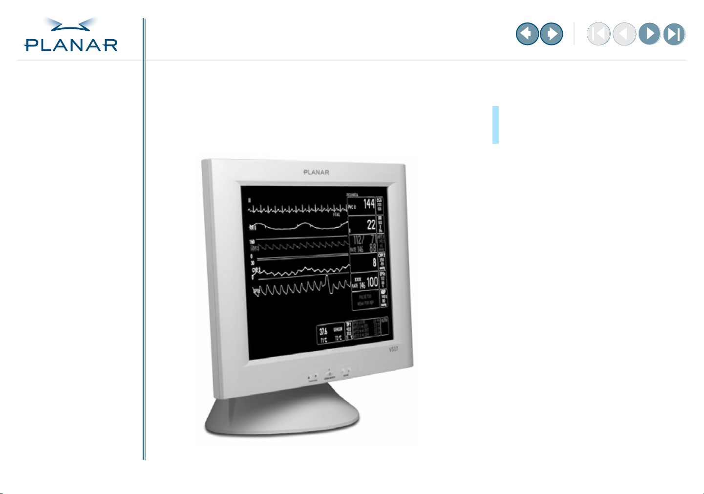
VS17 Display
VS17SXAD / VS15SXAD-TR
GETTING STARTED
About the Display
Unpack Display
Identify Components
Adjust Orientation/Angle
INSTALLING THE DISPLAY
Connect Power
Connect Video
Connect Audio
Connect Touch Screen
Power Management System
USING THE CONTROLS
Overview
Hot Key Functions
OSD Menu
Function Menus
OSD Lockout
APPENDIXES
Technical Information
Supported Timing
Troubleshooting
Operations Manual
www.planar.com
Page 2
QUICK LINKS
Contents
FCC Compliance Statement
Index
Ordering Parts
Product Information
Regulatory Compliance
Warranty
GETTING STARTED
About the Display
Unpack Display
Identify Components
Adjust Orientation/Angle
INSTALLING THE DISPLAY
Connect Power
Connect Video
Connect Audio
Connect Touch Screen
Power Management System
USING THE CONTROLS
Overview
Hot Key Functions
OSD Menu
Function Menus
OSD Lockout
Copyright © Planar Systems, Inc., 2004. All rights reserved.
Information in this document has been carefully checked for accuracy; however, no guarantee is
given to the correctness of the contents. This document is subject to change without notice. Planar
provides this information as reference only. Reference to other vendors’ product does not imply
any recommendation or endorsement.
This document contains proprietary information protected by copyright. No part of this manual
may be reproduced by any mechanical, electronic, or other means, in any form, without prior
written permission of the manufacturer.
Planar is a registered trademark and VS17 a trademark of Planar Systems, Inc.
All other trademarks are the property of their respective owners.
DOCUMENT HISTORY
August 2004 020-0318-00B
February 2004 020-0318-00A
America Sales
Planar Systems, Inc.
1195 NW Compton Drive
Beaverton, OR 97006-1992 USA
(503) 748-1100 phone
(503) 748-1493 fax
Medical Sales
Planar Systems, Inc.
400 Fifth Avenue
Waltham, MA 02451-8738 USA
(781) 895-1155 phone
(781) 895-1133 fax
Europe & Asia-Pacific Sales
European Representative
Planar Systems, Inc.
Olarinluoma 9, P. O. Box 46
FIN-02201 Espoo, Finland
+ 358 9 420 01 phone
+ 358 9 420 0200 fax
medicalsales@planar.com
medicalsupport@planar.com
www.planar.com
APPENDIXES
Technical Information
Supported Timing
Troubleshooting
VS17 Display
ii
Page 3
QUICK LINKS
Contents
FCC Compliance Statement
Index
Ordering Parts
Product Information
Regulatory Compliance
Warranty
GETTING STARTED
About the Display
Unpack Display
Identify Components
Adjust Orientation/Angle
INSTALLING THE DISPLAY
Connect Power
Connect Video
Connect Audio
Connect Touch Screen
Power Management System
USING THE CONTROLS
Overview
Hot Key Functions
OSD Menu
Function Menus
OSD Lockout
APPENDIXES
Technical Information
Supported Timing
Troubleshooting
Contents
Regulatory Compliance
FCC Compliance Statement
Product Information
Getting Started
1
About the VS17 Display
Unpack the Display
Identify the Components
Adjust the Orientation/Viewing Angle
2
Installing the Display
Connect the AC Power
Connect the Video Cable
Connect the Audio
Connect the Optional Touch Screen
Power Management System
Using the Controls
3
Overview of Display Controls
Hot Key Functions
Onscreen Display Main Menu
Function Menus
Onscreen Display Lockout
Appendix A: Technical Information
Appendix B: Supported Timing
Appendix C: Troubleshooting
Index
Description of Warranty
Ordering Information
VS17 Display
. . . . . . . . . . . . . . . . . . . . . . . . . . . . . . . . . . . . . iv
. . . . . . . . . . . . . . . . . . . . . . . . . . . . . . . . . vi
. . . . . . . . . . . . . . . . . . . . . . . . . . . . . . . . . . . . . . vii
. . . . . . . . . . . . . . . . . . . . . . . . . . . . . . . . . . . . . . 1
. . . . . . . . . . . . . . . . . . . . . . . . . . . . . . . . . . . . . . . . . 2
. . . . . . . . . . . . . . . . . . . . . . . . . . . . . . . . . . . . . 3
. . . . . . . . . . . . . . . . . . . . . . . . . . . . 5
. . . . . . . . . . . . . . . . . . . . . . . . . . . . . . . . . . . . . . 6
. . . . . . . . . . . . . . . . . . . . . . . . . . . . . . . . . . . . . 7
. . . . . . . . . . . . . . . . . . . . . . . . . . . . . . . . . . . . . . . . . 8
. . . . . . . . . . . . . . . . . . . . . . . . . . . . . . 9
. . . . . . . . . . . . . . . . . . . . . . . . . . . . . . . . . . 10
. . . . . . . . . . . . . . . . . . . . . . . . . . . . . . . . . 11
. . . . . . . . . . . . . . . . . . . . . . . . . . . . . . . . . . . . . . . . 12
. . . . . . . . . . . . . . . . . . . . . . . . . . . . . . . . . 13
. . . . . . . . . . . . . . . . . . . . . . . . . . . . . . . . . . . . . . . . . . 14
. . . . . . . . . . . . . . . . . . . . . . . . . . . . . . . . . . . 21
. . . . . . . . . . . . . . . . . . . . . . . . . . . 22
. . . . . . . . . . . . . . . . . . . . . . . . . . . . . . 23
. . . . . . . . . . . . . . . . . . . . . . . . . . . . . . . 24
. . . . . . . . . . . . . . . . . . . . . . . . . . . . . . . . . . . . . . . . . . . . . . . . . 25
. . . . . . . . . . . . . . . . . . . . . . . . . . . . . . . . . . . 27
. . . . . . . . . . . . . . . . . . . . . . . . . . . . . . . . . . . . . 30
iii
Page 4

QUICK LINKS
Contents
FCC Compliance Statement
Index
Ordering Parts
Product Information
Regulatory Compliance
Warranty
GETTING STARTED
About the Display
Unpack Display
Identify Components
Adjust Orientation/Angle
INSTALLING THE DISPLAY
Connect Power
Connect Video
Connect Audio
Connect Touch Screen
Power Management System
USING THE CONTROLS
Overview
Hot Key Functions
OSD Menu
Function Menus
OSD Lockout
APPENDIXES
Technical Information
Supported Timing
Troubleshooting
Regulatory Compliance
This display has been tested and found to comply with IEC/EN 60601-1 and IEC/EN 60601-1-2
standards, and is certified to meet medical standard C22.2 No. 601.1-M1990 (C US Mark).
The medical display, in addition to meeting medical requirements, has been tested and found to
comply with the limits for Federal Communications Commission (FCC) Class B computing devices in
a typically configured system since many medical offices are located in residential areas. It is the
system integrator’s responsibility to test and ensure that the entire system complies with applicable
electromagnetic compatibility (EMC) laws.
Planar Systems, Inc. has made great efforts to support the medical device industry, in particular,
medical device manufacturers and medical device system integrators. We offer state-of-the-art
color displays that are compliant with worldwide accepted medical device safety standards, and for
the European market, CE-marked displays based on compliance with counsel directive 93/42/EEC—
commonly referred to as the Medical Device Directive (MDD). The following summarizes our
qualification of these displays as it relates to compliance with the MDD.
The European Medical Device Directive requires that the intended use of the device be defined.
The intended use of these displays is “to display alphanumeric, graphic, and image data as inputted
from any type of medical device.” These displays do not provide a measurement function in any
way, and it is the device and systems manufacturer’s responsibility to verify its function in the
integrated device or system.
The display was classified as required by the MDD according to Annex IX of the directive and the
medical device (MEDDEV) guidance available at the time of classification. Because the display uses
electrical energy and has no direct patient connections and—by itself—no medical utility, the
display is classified according to Rule 12 as an MDD Class I device, component, or accessory. The
MDD states that manufacturers of Class I medical devices or accessories shall satisfy the
requirements in regard to design and manufacturing controls, that is, the applicable assessment
route to be used for CE-marking under the MDD, and it shall carry the CE mark according to
Annex XII of the directive, with no notified body annotation.
The applicable safety standards for an MDD Class I display are IEC/EN 60601-1:1990 along with
Amendments 1 and 2. To help the medical device designer evaluate the suitability of these displays,
Planar has also conducted EMC testing to IEC 60601-1-2 as it can be applied. The display with its
power supply alone does not represent a functional medical device. Hence, Planar configured
a minimal operating system to exercise the display. The resulting data are made available to
interested parties.
VS17 Display
–MORE–
iv
Page 5

QUICK LINKS
Contents
FCC Compliance Statement
Index
Ordering Parts
Product Information
Regulatory Compliance
Warranty
GETTING STARTED
About the Display
Unpack Display
Identify Components
Adjust Orientation/Angle
INSTALLING THE DISPLAY
Connect Power
Connect Video
Connect Audio
Connect Touch Screen
Power Management System
USING THE CONTROLS
Overview
Hot Key Functions
OSD Menu
Function Menus
OSD Lockout
This is informative data, not certification data. Certification data must be obtained by the device or
system integrator according to Article 12 of the MDD titled “Particular procedure for systems and
procedure packs.” Paragraph 2 clearly outlines the device or system integrator’s responsibility in
this matter.
In summary, Planar Systems, Inc. is CE-marking these displays under the Medical Device Directive,
which establishes compliance to the basic medical safety standards. However, EMC compliance can
only be accomplished in the configured medical device or system and is the responsibility of the
device or system manufacturer. Planar has the necessary documentation such as IEC 60601-1
notified body and other third-party test reports and certifications, a risk/hazard analysis, an
essential requirements checklist, and the Planar International Electrotechnical Commission (IEC)
declaration of conformity.
Planar Systems, Inc., located in Beaverton, Oregon, USA, is the manufacturer of these displays in
the meaning of the directive. As required by the MDD in Article 14, Planar Systems, Inc., not residing
in the European Economic Area (EEA), has a European representative, Planar Systems, Inc.—
Olarinluoma 9, P.O. Box 46, FIN-02201Espoo, Finland (phone + 358 9 420 01; fax +358 9 420 0200).
In the opinion of Planar Systems, Inc. registration required to put this device into commerce is the
responsibility of the medical device/system manufacturer, and Planar supports this requirement by
providing a European Commission (EC) declaration of conformity. If Planar supplies a display to an
end user, rather than a device manufacturer, it is the end user’s responsibility to ensure continued
compliance with the MDD of the system in which the display is integrated.
For vigilance reporting as required under Article 10 of the MDD, Planar Systems, Inc. will provide
any information requested by competent authority to support any reported incident investigation
by such an authority.
European Union Declaration of Conformity for Medical Applications
A Declaration of Conformity has been filed for this product. For additional copies of the Declaration
of Conformity document, contact Planar Systems, Inc.
APPENDIXES
Technical Information
Supported Timing
Troubleshooting
VS17 Display
v
Page 6

QUICK LINKS
Contents
FCC Compliance Statement
Index
Ordering Parts
Product Information
Regulatory Compliance
Warranty
GETTING STARTED
About the Display
Unpack Display
Identify Components
Adjust Orientation/Angle
INSTALLING THE DISPLAY
Connect Power
Connect Video
Connect Audio
Connect Touch Screen
Power Management System
USING THE CONTROLS
Overview
Hot Key Functions
OSD Menu
Function Menus
OSD Lockout
FCC Compliance Statement
This equipment has been tested and found to comply with the limits for a Class B digital device,
pursuant to Part 15 of the FCC Rules. These limits are designed to provide reasonable protection
against harmful interference when the equipment is operated in a residential installation. This
equipment generates, uses, and can radiate radio frequency energy and, if not installed and used in
accordance with the instruction manual, may cause harmful interference to radio communications.
However, there is no guarantee that interference will not occur in a particular installation. If this
equipment does cause harmful interference to radio or television reception, which can be
determined by turning the equipment off and on, you are encouraged to try to correct the
interference by one or more of the following measures:
•
Reorient or relocate the receiving antenna.
•
Increase the separation between the equipment and the receiver.
•
Connect the equipment into an outlet different from that to which the receiver
is connected.
•
Consult the dealer or an experienced radio/TV technician for help.
To comply with the limits for an FCC Class B computing device, always use the shielded signal cord
and shielded power cord supplied with this unit.
The Federal Communications Commission warns that changes or modifications of the unit not
expressly approved by the party responsible for compliance could void the user’s authority to
operate the equipment.
APPENDIXES
Technical Information
Supported Timing
Troubleshooting
VS17 Display
vi
Page 7
QUICK LINKS
Contents
FCC Compliance Statement
Index
Ordering Parts
Product Information
Regulatory Compliance
Warranty
GETTING STARTED
About the Display
Unpack Display
Identify Components
Adjust Orientation/Angle
INSTALLING THE DISPLAY
Connect Power
Connect Video
Connect Audio
Connect Touch Screen
Power Management System
USING THE CONTROLS
Overview
Hot Key Functions
OSD Menu
Function Menus
OSD Lockout
APPENDIXES
Technical Information
Supported Timing
Troubleshooting
Product Information
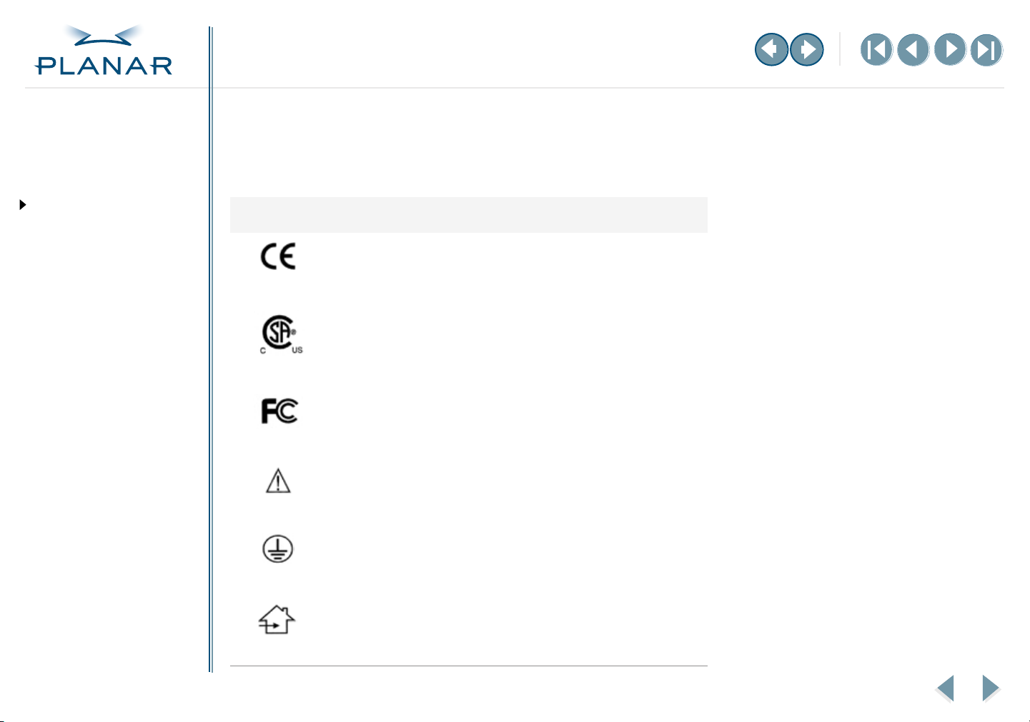
Symbol explanations
These symbols appear on the display or power adapter.
Symbol
VS17 Display
Description
Proof of conformity to applicable European Economic Community
Council directives.
The product has been tested and certified by CSA to C22.2
No. 601.1-M1990. If this mark appears with the indicators "C" and
"US," the product is certified for the U.S. and Canadian markets,
meeting the applicable U.S. and Canadian standards.
The product has been tested to comply with FCC Class B standards.
More information available in accompanying documents.
Protective earth ground.
Indoor use only.
–MORE–
vii
Page 8

QUICK LINKS
Contents
FCC Compliance Statement
Index
Ordering Parts
Product Information
Regulatory Compliance
Warranty
GETTING STARTED
About the Display
Unpack Display
Identify Components
Adjust Orientation/Angle
INSTALLING THE DISPLAY
Connect Power
Connect Video
Connect Audio
Connect Touch Screen
Power Management System
USING THE CONTROLS
Overview
Hot Key Functions
OSD Menu
Function Menus
OSD Lockout
APPENDIXES
Technical Information
Supported Timing
Troubleshooting
Safety instructions
Store the display in its original shipping carton when it is not in operation for extended
periods of time. Also use the original packing materials and carton when shipping the display.
•
Do not place the display near a window. Exposing the display to rain, water, moisture, or
constant direct sunlight can damage it.
•
Do not place anything on top of the display-to-computer signal cord. Make sure the cord is
clear of foot traffic.
•
Do not apply excessive pressure to the screen.
Do not operate the touch screen with sharp objects, such as a scalpel. Sharp objects can
•
scratch or damage the touch screen. A damaged touch screen may pose a safety hazard.
Refer all servicing to qualified personnel to maintain your warranty. The display and power
•
supply units contain no user-serviceable parts.
•
Do not cover or obstruct the venting holes on the back of the display.
•
Store the display in an environment with a temperature range from -20° to 65° C
(from -4° to 149° F). Storing your display outside the temperature range could
result in permanent damage.
•
Replace any cord or cable that is frayed or damaged with another of the same type and
rating as supplied by Planar. (See “Ordering Information” on page 30 for part numbers.)
The safety and regulatory listings and certifications are based on the cable supplied by
Planar.
Do not expose the display to liquid or drop it. If the case has been damaged, the unit may
•
pose a shock or fire hazard. Unplug the unit and call customer service for assistance.
•
Use only the power adapter that has been tested and approved for use with this display
product. (See “Ordering Information” on page 30 for part numbers.) The power adapter
must be plugged into a grounded power outlet.
Use a cloth dampened with liquid cleaner to clean the power adapter. Wipe the outside of
•
the enclosure and cable only. Do not immerse the adapter in liquid, or a safety hazard
could arise during use.
Do not use the power adapter near inflammable anesthetics.
•
VS17 Display
–MORE–
viii
Page 9
QUICK LINKS
Contents
FCC Compliance Statement
Index
Ordering Parts
Product Information
Regulatory Compliance
Warranty
GETTING STARTED
About the Display
Unpack Display
Identify Components
Adjust Orientation/Angle
INSTALLING THE DISPLAY
Connect Power
Connect Video
Connect Audio
Connect Touch Screen
Power Management System
USING THE CONTROLS
Overview
Hot Key Functions
OSD Menu
Function Menus
OSD Lockout
Cleaning instructions
The VS17SXAD models will continue to operate while being cleaned in a fashion normal for
a hospital environment. The display withstands nonabrasive cloths and cleaning solutions
used on similar equipment.
Do not spray liquid cleaners directly onto the screen. Stand away from the display and apply
the cleaning solution onto a clean nonabrasive cloth.
Use a damp cloth with the cleaning solution for all surfaces. (You can also use 70% isopropyl
alcohol to clean the touchscreen surface.) Without applying excessive pressure, clean the
screen with the slightly dampened cloth. Dry the screen with a clean nonabrasive cloth to
remove any residue.
Disposal Information
The VS17SXAD models contains cold cathode fluorescent lamps, which contain
a maximum of 20 milligrams of mercury (5 milligrams per lamp). Follow local
ordinances or regulations for its disposal.
Possible cleaning solutions
•
70% isopropyl alcohol
•
1.6% aqueous ammonia
Cidex® (2.4% glutaraldehyde
•
solution)
Sodium hypochlorite (bleach)
•
10%
“Green soap” United States
•
Pharmacopoeia (USP)
•
0.5% Chlorhexidine in 70%
isopropyl alcohol
•
Ovation®
•
Formula 409®
fantastik®
•
•
WexCide®
APPENDIXES
Technical Information
Supported Timing
Troubleshooting
VS17 Display
ix
Page 10
QUICK LINKS
Contents
FCC Compliance Statement
Index
Ordering Parts
Product Information
Regulatory Compliance
Warranty
GETTING STARTED
About the Display
Unpack Display
Identify Components
Adjust Orientation/Angle
INSTALLING THE DISPLAY
Connect Power
Connect Video
Connect Audio
Connect Touch Screen
Power Management System
USING THE CONTROLS
Overview
Hot Key Functions
OSD Menu
Function Menus
OSD Lockout
About the VS17 Display
The architecture of the VS17 display incorporates an active matrix liquid-crystal
display (AMLCD) panel that produces a bright, high-contrast image with low
radiation emission. This technology greatly reduces the radiation-related health
concerns associated with cathode-ray tube (CRT) monitors.
The VS17 is a high-resolution color display designed to be versatile and easy to use.
The display accepts either analog or digital video (DVI) input and displays most video
standards from 640 x 480 (VGA standard) to 1280 x 1024 (SXGA standard). The
controls located on the front panel allow you to easily adjust the display parameters
using onscreen display (OSD) menus.
Digital video input is a single-link, transition minimized differential signaling (TMDS)
digital visual interface (DVI), and is in compliance with the Digital Display Working
Group (DDWG) DVI standard. This interface produces the sharpest display image
possible with little need for adjustment. The setup is Plug and Play. The display
complies with the VESA DDC1 and DDC2B protocols for analog mode. For more
information, refer to the VESA standard DDCC Interface.
This display has been designed, tested, and certified for use within the patient
vicinity. It has lower electric discharge, thus reducing the likelihood of electric shock.
The display is certified to UL-2601, IE 60601-1, and other representatives of the most
stringent electric discharge certifications available. In addition, the interface buttons
on the front panel are sealed by a plastic membrane, allowing simpler and safer
cleaning. The display also meets the liquid/particle ingress certifications, IPX1.
For more information, see the display specification.
Display features
Built-in platform that conforms
to the VESA mounting standard.
The display is mountable on the
following devices:
Articulated swing arm
•
Desk stand
•
Wall bracket
•
Rugged display housing that
makes the unit ideal for hospital
applications. The acrylic cover
protects the display from bumps,
falls, collisions, and even everyday
cleaning.
Configuration management to
ensure that you receive a consistent
and predictable product.
APPENDIXES
Technical Information
Supported Timing
Troubleshooting
VS17 Display
1
Page 11
QUICK LINKS
Contents
FCC Compliance Statement
Index
Ordering Parts
Product Information
Regulatory Compliance
Warranty
GETTING STARTED
About the Display
Unpack Display
Identify Components
Adjust Orientation/Angle
INSTALLING THE DISPLAY
Connect Power
Connect Video
Connect Audio
Connect Touch Screen
Power Management System
USING THE CONTROLS
Overview
Hot Key Functions
OSD Menu
Function Menus
OSD Lockout
Unpack the Display
Make sure you receive the following items. If any item is missing or damaged,
see your dealer immediately.
•
LCD screen
•
Desk stand or VESA mounting plate
•
Integrated VGA-VGA-audio cable
•
Integrated DVI-DVI-audio cable
•
Serial cables (VS17SXAD-TR only)
•
AC power adapter with 1.5-meter (5-foot) cable
•
Medical-grade power cord (U.S. or European)
•
Documentation package, including EU Declaration of Conformity,
quick setup guide, and CD with touchscreen driver and PDF file of
this manual
Selecting a workspace
Before you unpack the VS17 display,
select a suitable workspace for the
display and computer. You need a
stable, level, and clean surface near a
wall outlet.
Even though this display uses little
power, place it in a location that
allows sufficient airflow to ensure
proper ventilation.
Avoid setting up the display near
a window where sunlight often
comes in. You will have difficulty
seeing the screen with glare
reflecting off the display.
APPENDIXES
Technical Information
Supported Timing
Troubleshooting
VS17 Display
2
Page 12
QUICK LINKS
Contents
FCC Compliance Statement
Index
Ordering Parts
Product Information
Regulatory Compliance
Warranty
GETTING STARTED
About the Display
Unpack Display
Identify Components
Adjust Orientation/Angle
INSTALLING THE DISPLAY
Connect Power
Connect Video
Connect Audio
Connect Touch Screen
Power Management System
USING THE CONTROLS
Overview
Hot Key Functions
OSD Menu
Function Menus
OSD Lockout
APPENDIXES
Technical Information
Supported Timing
Troubleshooting
Identify the Components
The VS17 display provides easy access to all controls and peripheral ports.
The following illustrations of the front and back panels identify the display controls
and ports.
Front panel
5
3
6
4
VS17 Display
1
2
Legend
1 LCD screen
A 17-inch diagonal AMLCD.
The screen supports a maximum
resolution of 1280 x 1024 (SXGA).
2 Function UP and DOWN buttons
Vertical arrows to navigate
the onscreen display horizontally.
Select the icons to the left or right.
3 Power ON indicator
An LED indicator that stays lit
when the power is on and the
display is receiving a proper
video signal. The LED blinks
slowly when the display is in
power-saving mode.
4 Power/Menu
Dual function button for the
power switch and onscreen
display menu.
5 Adjust PLUS and MINUS buttons
Controls to change the value of
the selected icon.
6 Desk stand
Flat-surface support for the
display. The stand allows you
to both rotate the screen to
landscape or portrait and tilt the
screen to various viewing angles.
3
Page 13

QUICK LINKS
Contents
FCC Compliance Statement
Index
Ordering Parts
Product Information
Regulatory Compliance
Warranty
GETTING STARTED
About the Display
Unpack Display
Identify Components
Adjust Orientation/Angle
INSTALLING THE DISPLAY
Connect Power
Connect Video
Connect Audio
Connect Touch Screen
Power Management System
USING THE CONTROLS
Overview
Hot Key Functions
OSD Menu
Function Menus
OSD Lockout
Back panel
3
24
1
5
6
1 Power input (locking mini
DIN connector)
Port for the power connector.
2 Audio Line In
Jack for the audio cable. (You can
also connect the CD-ROM Line Out
to this jack.)
3 Touchscreen port
Port for the RS-232 cable; used to
operate the optional touch screen.
This cable is provided with the
Optional Touch Screen package.
4 DVI connector
Port for digital video cable.
5 VGA connector
Port for a 1.5-meter cable with two
15-pin D-Sub VGA connectors.
6 Stereo speakers
Two transmission channels
for sound.
Legend
APPENDIXES
Technical Information
Supported Timing
Troubleshooting
VS17 Display
4
Page 14

QUICK LINKS
Contents
FCC Compliance Statement
Index
Ordering Parts
Product Information
Regulatory Compliance
Warranty
GETTING STARTED
About the Display
Unpack Display
Identify Components
Adjust Orientation/Angle
INSTALLING THE DISPLAY
Connect Power
Connect Video
Connect Audio
Connect Touch Screen
Power Management System
USING THE CONTROLS
Overview
Hot Key Functions
OSD Menu
Function Menus
OSD Lockout
APPENDIXES
Technical Information
Supported Timing
Troubleshooting
Adjust the Orientation/Viewing Angle
You can rotate your VS17 display from landscape to portrait and tilt it downward or
upward to various viewing angles. The side view of the display shows the angle
settings possible, ranging from -5 degrees downward to 25 degrees upward.
1 Gently pull the lower half of the display toward you. You must tilt the display
upward before rotating it.
2 Use both hands to change the orientation of the display. Rotate the display
90° to the left (counterclockwise) until it stops in portrait mode.
3 Select, if necessary and/or available, the different option on the video card, or
display settings on the control panel.
4 Refer to www.portrait.com for software that allows conversion from land-
scape to portrait mode.
VS17 Display
5
Page 15

QUICK LINKS
Contents
FCC Compliance Statement
Index
Ordering Parts
Product Information
Regulatory Compliance
Warranty
GETTING STARTED
About the Display
Unpack Display
Identify Components
Adjust Orientation/Angle
INSTALLING THE DISPLAY
Connect Power
Connect Video
Connect Audio
Connect Touch Screen
Power Management System
USING THE CONTROLS
Overview
Hot Key Functions
OSD Menu
Function Menus
OSD Lockout
APPENDIXES
Technical Information
Supported Timing
Troubleshooting
Connect the AC Power
1 Plug the AC power cord into the power adapter.
2 Plug the power connector into the locking mini DIN port on the back panel.
Push the connector in until the locking mechanism clicks.
3 Plug the power cord into a grounded wall outlet.
VS17 Display
Installation tips
For displays mounted on a desk
stand, rotate the screen from landscape to portrait for easy access to
the ports. If you need to place your
display face down, lower it carefully
on a protective cloth.
Avoiding power surges
Use a surge protector between the
power adapter and the outlet to
prevent sudden current variations
from reaching the display.
“Unlocking” the power cord
To detach the cord, press down on
the plug housing and then pull out.
IN OPERATION: No power
Check that the display and
computer are both turned on.
Verify that the outlet is functioning.
Plug a lamp into the same outlet
to check.
Check the status of the LED indicator
on the power supply. If the green
light is off, call customer support.
Check the status of the LED indicator
on the display. If the display is on but
the green light is neither steady nor
blinking, call customer support.
6
Page 16

QUICK LINKS
Contents
FCC Compliance Statement
Index
Ordering Parts
Product Information
Regulatory Compliance
Warranty
GETTING STARTED
About the Display
Unpack Display
Identify Components
Adjust Orientation/Angle
INSTALLING THE DISPLAY
Connect Power
Connect Video
Connect Audio
Connect Touch Screen
Power Management System
USING THE CONTROLS
Overview
Hot Key Functions
OSD Menu
Function Menus
OSD Lockout
APPENDIXES
Technical Information
Supported Timing
Troubleshooting
Connect the Video Cable
1 Turn off your computer and display before connecting the two units.
2 Plug the video cable into the DVI port for digital mode or into the D-sub
VGA port for analog mode. (The illustration below shows the VGA
connection. The DVI connector is to the immediate left.)
3 Plug the other end of the cable into the video port on the computer.
4 Make sure the cable are properly aligned, then tighten the connecting screws
to ensure a secure connection.
5 Turn on the display first and then the computer.
VS17 Display
IN OPERATION: Blank screen
Check the LED indicator on the
display. If it is steady green, but you
have no image on the screen, check
that all connections are secure and
the power is on. If the problem still
exists, call customer support.
7
Page 17

QUICK LINKS
Contents
FCC Compliance Statement
Index
Ordering Parts
Product Information
Regulatory Compliance
Warranty
GETTING STARTED
About the Display
Unpack Display
Identify Components
Adjust Orientation/Angle
INSTALLING THE DISPLAY
Connect Power
Connect Video
Connect Audio
Connect Touch Screen
Power Management System
USING THE CONTROLS
Overview
Hot Key Functions
OSD Menu
Function Menus
OSD Lockout
Connect the Audio
1 Plug the audio cable to the Line Out on the audio card in your computer.
2 Plug the other end of the audio cable to the Line In jack on the display.
3 Adjust the volume of the stereo speakers by using the volume control
function on the onscreen display menu.
On volume control
In some instances, the volume
control function may be disabled.
If so, the volume has been preset
to the maximum.
Although the display speakers
are adequate for most audio
applications, Planar does not
recommend using the display
speakers as the exclusive audio
source for medical alarms or
applications critical for audio
performance.
IN OPERATION: No sound
Verify that your display unit has
speakers. Try loading a CD or
another audio program.
Check the volume setting on the
display and the computer. Disable
mute or increase the volume.
Check that the audio cable is
plugged into the OUTPUT on the
computer and INPUT on the display.
Plug headphones or speakers into
your computer to see if they
produce sound.
APPENDIXES
Technical Information
Supported Timing
Troubleshooting
VS17 Display
8
Page 18

QUICK LINKS
Contents
FCC Compliance Statement
Index
Ordering Parts
Product Information
Regulatory Compliance
Warranty
GETTING STARTED
About the Display
Unpack Display
Identify Components
Adjust Orientation/Angle
INSTALLING THE DISPLAY
Connect Power
Connect Video
Connect Audio
Connect Touch Screen
Power Management System
USING THE CONTROLS
Overview
Hot Key Functions
OSD Menu
Function Menus
OSD Lockout
Connect the Optional Touch Screen
1 Plug the RS232 cable into the RS232 port on the display.
2 Plug the other end of the cable to the RS232 serial port on your computer.
3 Load the touchscreen driver from the CD enclosed.
IN OPERATION: No touch
The CD shipped with your display
contains several touchscreen drivers.
Be sure the proper touchscreen driver
is installed on your computer.
If you have conflicts or any problems
with the driver, try reinstalling it.
If you continue to have problems,
then you need to determine the
source—the display or the computer.
Try using the display with another
computer, or installing the driver
on another display system.
If the problem still exists, contact
customer support.
APPENDIXES
Technical Information
Supported Timing
Troubleshooting
VS17 Display
9
Page 19

QUICK LINKS
Contents
FCC Compliance Statement
Index
Ordering Parts
Product Information
Regulatory Compliance
Warranty
GETTING STARTED
About the Display
Unpack Display
Identify Components
Adjust Orientation/Angle
INSTALLING THE DISPLAY
Connect Power
Connect Video
Connect Audio
Connect Touch Screen
Power Management System
USING THE CONTROLS
Overview
Hot Key Functions
OSD Menu
Function Menus
OSD Lockout
Power Management System
The VS17 display complies with the VESA Display Power Management Signaling
standard. The four power-saving modes listed below are based on the display
detecting the horizontal or vertical sync signal.
Mode AC Input Power LED Status
ON 60 watts maximum Steady green
Standby 6 watts maximum Blinking green
Suspend 6 watts maximum Blinking green
OFF 6 watts maximum OFF
When the display is in power-saving mode, or when it detects an incorrect
timing, the display screen goes blank and the power LED indicator blinks.
APPENDIXES
Technical Information
Supported Timing
Troubleshooting
VS17 Display
10
Page 20

QUICK LINKS
Contents
FCC Compliance Statement
Index
Ordering Parts
Product Information
Regulatory Compliance
Warranty
GETTING STARTED
About the Display
Unpack Display
Identify Components
Adjust Orientation/Angle
INSTALLING THE DISPLAY
Connect Power
Connect Video
Connect Audio
Connect Touch Screen
Power Management System
USING THE CONTROLS
Overview
Hot Key Functions
OSD Menu
Function Menus
OSD Lockout
APPENDIXES
Technical Information
Supported Timing
Troubleshooting
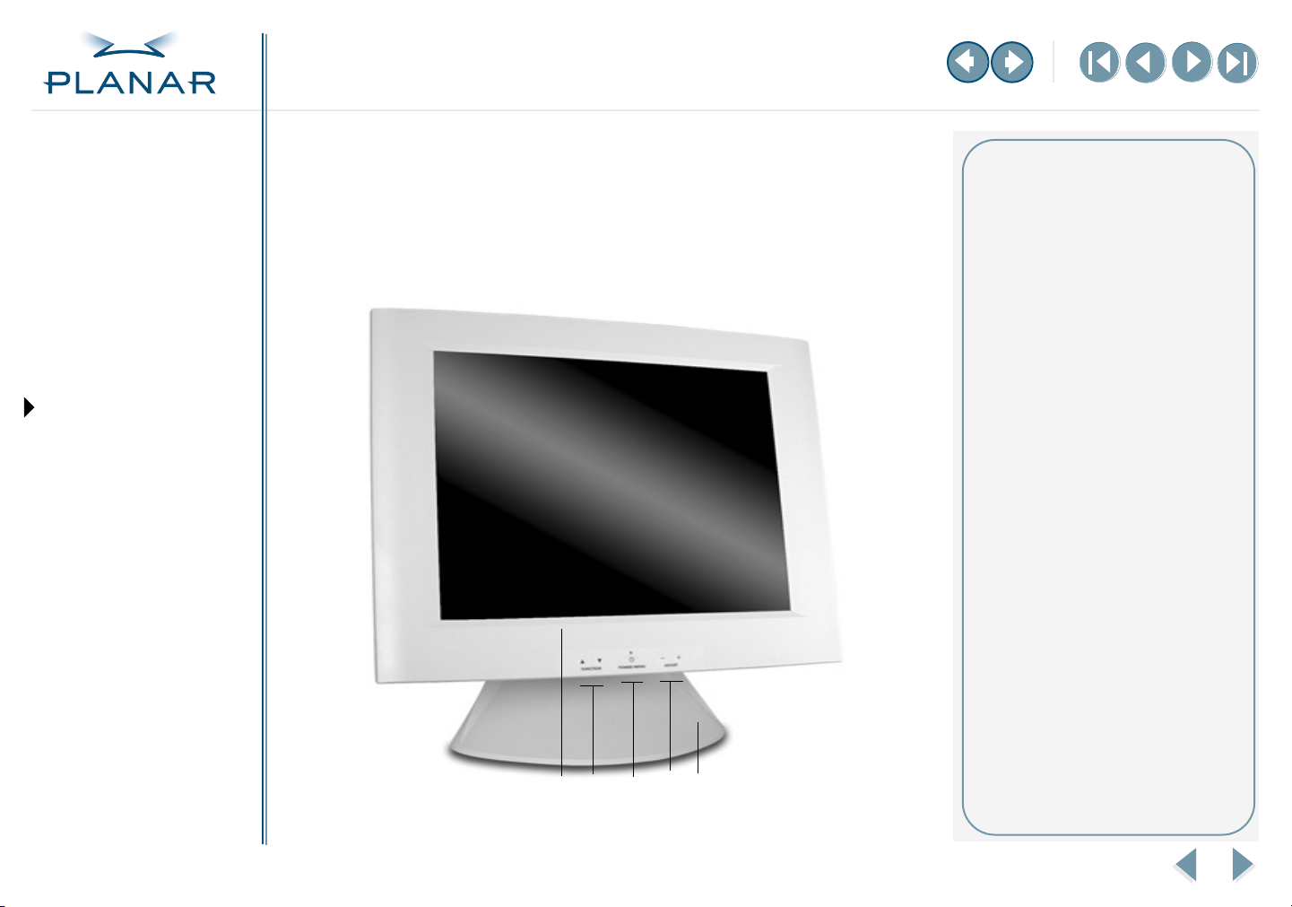
Overview of Display Controls
The onscreen display (OSD) menu is the user interface for controlling various
aspects of the VS17 display. Using the OSD menu, you can adjust functions such as
brightness, image fine-tuning, and speaker volume.
Use the push buttons on the front of the display to operate the controls. Access
the OSD menu by quickly pressing the Power/Menu button when the display
is powered-up. If your computer is in power-saving mode, or is powered-down,
the OSD menu is inaccessible.
1
VS17 Display
42
3
Legend
1 Function UP and DOWN buttons
Select the icons to the left or right.
2 LED power indicator
Is lit when the power is on and the
display is receiving a proper video
signal; blinks when the display is
in power-saving mode.
3 Power/Menu button
Turns the display ON or OFF (press
for a minimum of 2 seconds).
Activates the OSD main menu
with a quick press.
4 Adjust PLUS and MINUS buttons
Change the value of the selected
icon or select a menu item.
11
Page 21

QUICK LINKS
Contents
FCC Compliance Statement
Index
Ordering Parts
Product Information
Regulatory Compliance
Warranty
GETTING STARTED
About the Display
Unpack Display
Identify Components
Adjust Orientation/Angle
INSTALLING THE DISPLAY
Connect Power
Connect Video
Connect Audio
Connect Touch Screen
Power Management System
USING THE CONTROLS
Overview
Hot Key Functions
OSD Menu
Function Menus
OSD Lockout
Hot Key Functions
Three Hot Key functions allow you to make quick adjustments to the display setting,
volume, and contrast.
Auto Adjust. Press the Function
DOWN button to apply a display
setting automatically. A small Auto
Adjust OSD is also displayed.
(Analog mode only)
Audio-Volume. Press the Adjust
PLUS button to change the audio
volume directly. A small AudioVolume OSD is also displayed.
Contrast. Press the Adjust MINUS
button to change the contrast of
the display directly. A small contrast
OSD is also displayed.
APPENDIXES
Technical Information
Supported Timing
Troubleshooting
VS17 Display
12
Page 22

QUICK LINKS
Contents
FCC Compliance Statement
Index
Ordering Parts
Product Information
Regulatory Compliance
Warranty
GETTING STARTED
About the Display
Unpack Display
Identify Components
Adjust Orientation/Angle
INSTALLING THE DISPLAY
Connect Power
Connect Video
Connect Audio
Connect Touch Screen
Power Management System
USING THE CONTROLS
Overview
Hot Key Functions
OSD Menu
Function Menus
OSD Lockout
Onscreen Display Main Menu
This screen appears when you access the OSD main menu. The top row of icons
represents the main menus. When a menu item is highlighted, its submenu and
a description of the submenu item appear below the main menu bar.
IN OPERATION: Image quality
To correct poor image quality,
try the following:
• Bring up the OSD menu and
set the display to its native
resolution, refresh rate, and
maximum color depth.
• Auto adjust the display.
• Go to the Windows shutdown
screen and set phase.
• Verify that the computer settings
are compatible with the display.
Check the information on the
OSD menu. (See MISC-Control
menu.)
• If the problem still exists, call
customer support.
APPENDIXES
Technical Information
Supported Timing
Troubleshooting
VS17 Display
13
Page 23

QUICK LINKS
Contents
FCC Compliance Statement
Index
Ordering Parts
Product Information
Regulatory Compliance
Warranty
GETTING STARTED
About the Display
Unpack Display
Identify Components
Adjust Orientation/Angle
INSTALLING THE DISPLAY
Connect Power
Connect Video
Connect Audio
Connect Touch Screen
Power Management System
Function Menus
Analog Mode
Monitor–Control Menu
Monitor-Control. Allows you to adjust the display characteristics such as the horizontal or vertical position,
display phase, display clock, and factory reset. Adjusting these settings is necessary if the results from the
Auto Adjust function are not satisfactory.
Pressing the Adjust PLUS or MINUS button displays the Monitor-Control submenu. Use the Function UP or
DOWN button to select a submenu item.
Auto-Adjust. Select Auto-Adjust to set the display parameters to optimum values.
H-Position. Press the Adjust PLUS or MINUS button to move the display image left or right on a horizontal plane.
V-Position. Press the Adjust PLUS or MINUS button to move the display image up or down on a vertical plane.
Phase. Press the Adjust PLUS or MINUS button to fine-tune the display image.
Clock. Press the Adjust PLUS or MINUS button to adjust the display pixel number alignment.
USING THE CONTROLS
Overview
Hot Key Functions
OSD Menu
Function Menus
OSD Lockout
APPENDIXES
Technical Information
Supported Timing
Troubleshooting
VS17 Display
Reset. Press the Adjust PLUS or MINUS button to reset all the Monitor-Control submenu settings.
Graph/Text. Press the Function Enter button to switch between the text and graphic options.
Port-Select. Switch between analog and digital mode; if no signal comes the Auto-Detection function is activated.
Exit. Press the Adjust PLUS or MINUS button to exit the Monitor-Control submenu.
14
Page 24

QUICK LINKS
Contents
FCC Compliance Statement
Index
Ordering Parts
Product Information
Regulatory Compliance
Warranty
GETTING STARTED
About the Display
Unpack Display
Identify Components
Adjust Orientation/Angle
INSTALLING THE DISPLAY
Connect Power
Connect Video
Connect Audio
Connect Touch Screen
Power Management System
USING THE CONTROLS
Overview
Hot Key Functions
OSD Menu
Function Menus
OSD Lockout
OSD–Control Menu
OSD-Control. Allows you to adjust the position of the onscreen display.
Pressing the Adjust PLUS or MINUS button displays the OSD-Control submenu. Use the Function UP or
DOWN button to select a submenu item.
OSD-H-Position. Press the Adjust PLUS or MINUS button to change the position of the OSD on a horizontal plane.
OSD-V-Position. Press the Adjust PLUS or MINUS button to change the position of the OSD on a vertical plane.
OSD-Timer. Use the Adjust PLUS or MINUS button to change the OSD display time
Exit. Press the Adjust PLUS or MINUS button to exit the OSD-Control submenu.
APPENDIXES
Technical Information
Supported Timing
Troubleshooting
VS17 Display
15
Page 25

QUICK LINKS
Contents
FCC Compliance Statement
Index
Ordering Parts
Product Information
Regulatory Compliance
Warranty
GETTING STARTED
About the Display
Unpack Display
Identify Components
Adjust Orientation/Angle
INSTALLING THE DISPLAY
Connect Power
Connect Video
Connect Audio
Connect Touch Screen
Power Management System
USING THE CONTROLS
Overview
Hot Key Functions
OSD Menu
Function Menus
OSD Lockout
APPENDIXES
Technical Information
Supported Timing
Troubleshooting
Graphic–Control Menu
Graphic-Control. Allows you to adjust the display contrast, brightness, sharpness, and color settings.
Pressing the Adjust PLUS or MINUS button displays the Graphic-Control submenu. Use the Function UP or
DOWN button to select a submenu item.
Contrast. Press the Adjust PLUS or MINUS button to adjust the difference between the lightest and darkest areas of
the display screen. You can set the contrast level from 0 to 31.
Brightness. Press the Adjust PLUS or MINUS button to adjust the light level on the display screen Make this adjustment in
conjunction with the Contrast parameter.
Color. Press the Adjust PLUS or MINUS button to select the display color. The available options are 9300, 6500, and User.
The 9300 and 6500 options allow you to set the Color Temperature to CIE coordinate value 9300 and 6500 degrees
respectively. Selecting the User option allows you to customize the Red, Green, and Blue coordinates.
R, G, B. Press the Adjust PLUS or MINUS button to make individual adjustments to the Red, Green, and Blue coordinates for
the customized color temperature. There are 128 levels of adjustments (0 to 127) available. Before adjusting these fields,
select the User option in the Color submenu.
Auto-Level. Select Auto-Level to automatically set the white balance display.
Reset. Press the Adjust PLUS or MINUS button to reset Color, Brightness, and Color parameters.
Exit. Press the Adjust PLUS or MINUS button to exit the Graphic-Control submenu.
VS17 Display
16
Page 26

QUICK LINKS
Contents
FCC Compliance Statement
Index
Ordering Parts
Product Information
Regulatory Compliance
Warranty
GETTING STARTED
About the Display
Unpack Display
Identify Components
Adjust Orientation/Angle
INSTALLING THE DISPLAY
Connect Power
Connect Video
Connect Audio
Connect Touch Screen
Power Management System
USING THE CONTROLS
Overview
Hot Key Functions
OSD Menu
Function Menus
OSD Lockout
APPENDIXES
Technical Information
Supported Timing
Troubleshooting
Miscellaneous–Control Menu
MISC-Control. Allows you to select the display language, adjust the volume setting, and view system information.
Pressing the Adjust PLUS or MINUS button displays the MISC-Control submenu. Use the Function UP or
DOWN button to select a submenu item.
Language. Press the Adjust PLUS or MINUS button to select a OSD display language. Languages supported:
English, German, French, Spanish, and Italian.
Audio Volume. Press the Adjust PLUS or MINUS button to decrease or increase the volume of the stereo speakers.
Information. Select this item to see the current display mode and firmware version.
Exit. Press the Adjust PLUS button to exit the MISC-Control submenu.
Exit Menu
Exit. Closes the onscreen display program.
Pressing the Adjust PLUS or MINUS button, when the OSD Exit item is selected, exits the OSD menu.
The OSD menu exits automatically when left inactive.
VS17 Display
17
Page 27

QUICK LINKS
Contents
FCC Compliance Statement
Index
Ordering Parts
Product Information
Regulatory Compliance
Warranty
GETTING STARTED
About the Display
Unpack Display
Identify Components
Adjust Orientation/Angle
Digital Mode
Monitor–Control Menu
Monitor-Control. Allows you to adjust the display characteristics.
Pressing the Adjust PLUS or MINUS button displays the Monitor-Control submenu. Use the Function UP or
DOWN button to select a submenu item.
Port-Select. Switch between analog and digital mode; if no signal comes the Auto-Detection function is activated.
Exit. Press the Adjust PLUS or MINUS button to exit the Monitor-Control submenu.
INSTALLING THE DISPLAY
Connect Power
Connect Video
Connect Audio
Connect Touch Screen
Power Management System
USING THE CONTROLS
Overview
Hot Key Functions
OSD Menu
Function Menus
OSD Lockout
APPENDIXES
Technical Information
Supported Timing
Troubleshooting
OSD–Control Menu
VS17 Display
OSD-Control. Allows you to adjust the position of the onscreen display.
Pressing the Adjust PLUS or MINUS button displays the OSD-Control submenu. Use the Function UP or
DOWN button to select a submenu item.
OSD-H-Position. Press the Adjust PLUS or MINUS button to change the position of the OSD on a horizontal plane.
OSD-V-Position. Press the Adjust PLUS or MINUS button to change the position of the OSD on a vertical plane.
OSD-Timer. Use the Adjust PLUS or MINUS button to change the OSD display time.
Exit. Press the Adjust PLUS or MINUS button to exit the OSD-Control submenu.
18
Page 28

QUICK LINKS
Contents
FCC Compliance Statement
Index
Ordering Parts
Product Information
Regulatory Compliance
Warranty
GETTING STARTED
About the Display
Unpack Display
Identify Components
Adjust Orientation/Angle
INSTALLING THE DISPLAY
Connect Power
Connect Video
Connect Audio
Connect Touch Screen
Power Management System
USING THE CONTROLS
Overview
Hot Key Functions
OSD Menu
Function Menus
OSD Lockout
Graphic–Control Menu
Graphic-Control. Allows you to adjust the display contrast, brightness, sharpness, and color settings.
Pressing the Adjust PLUS or MINUS button displays the Graphic-Control submenu. Use the Function UP or
DOWN button to select a submenu item.
Contrast. Press the Adjust PLUS or MINUS button to adjust the difference between the lightest and darkest areas of
the display screen. You can set the contrast level from 0 to 31.
Brightness. Press the Adjust PLUS or MINUS button to adjust the light level on the display screen Make this adjustment in
conjunction with the Contrast parameter.
Reset. Press the Adjust PLUS or MINUS button to reset Color, Brightness, and Color parameters.
Exit. Press the Adjust PLUS or MINUS button to exit the Graphic-Control submenu.
APPENDIXES
Technical Information
Supported Timing
Troubleshooting
VS17 Display
19
Page 29

QUICK LINKS
Contents
FCC Compliance Statement
Index
Ordering Parts
Product Information
Regulatory Compliance
Warranty
GETTING STARTED
About the Display
Unpack Display
Identify Components
Adjust Orientation/Angle
INSTALLING THE DISPLAY
Connect Power
Connect Video
Connect Audio
Connect Touch Screen
Power Management System
USING THE CONTROLS
Overview
Hot Key Functions
OSD Menu
Function Menus
OSD Lockout
APPENDIXES
Technical Information
Supported Timing
Troubleshooting
Miscellaneous–Control Menu
MISC-Control. Allows you to select the display language, adjust the volume setting, and view system information.
Pressing the Adjust PLUS or MINUS button displays the MISC-Control submenu. Use the Function UP or
DOWN button to select a submenu item.
Language. Press the Adjust PLUS or MINUS button to select a OSD display language. Languages supported:
English, German, French, Spanish, and Italian.
Audio Volume. Press the Adjust PLUS or MINUS button to decrease or increase the volume of the stereo speakers.
Information. Select this item to see the current display mode and firmware version.
Exit. Press the Adjust PLUS button to exit the MISC-Control submenu.
Exit Menu
Exit. Closes the onscreen display program.
Pressing the Adjust PLUS or MINUS button, when the OSD Exit item is selected, exits the OSD menu.
The OSD menu exits automatically when left inactive.
VS17 Display
20
Page 30

QUICK LINKS
Contents
FCC Compliance Statement
Index
Ordering Parts
Product Information
Regulatory Compliance
Warranty
GETTING STARTED
About the Display
Unpack Display
Identify Components
Adjust Orientation/Angle
INSTALLING THE DISPLAY
Connect Power
Connect Video
Connect Audio
Connect Touch Screen
Power Management System
USING THE CONTROLS
Overview
Hot Key Functions
OSD Menu
Function Menus
OSD Lockout
Onscreen Display Lockout
The VS17 display incorporates an OSD lockout function that you toggle active or
inactive. Pressing three controls simultaneously—Function DOWN, Adjust PLUS,
and Adjust MINUS—keeps the onscreen display from being enabled by the power
control. The message Key Lock briefly appears onscreen. During lockout, the OSD
menu does not appear. To unlock the onscreen display, press the same three
controls again simultaneously. The message Key Unlock appears briefly.
APPENDIXES
Technical Information
Supported Timing
Troubleshooting
VS17 Display
21
Page 31

QUICK LINKS
Contents
FCC Compliance Statement
Index
Ordering Parts
Product Information
Regulatory Compliance
Warranty
GETTING STARTED
About the Display
Unpack Display
Identify Components
Adjust Orientation/Angle
INSTALLING THE DISPLAY
Connect Power
Connect Video
Connect Audio
Connect Touch Screen
Power Management System
USING THE CONTROLS
Overview
Hot Key Functions
OSD Menu
Function Menus
OSD Lockout
APPENDIXES
Technical Information
Supported Timing
Troubleshooting
Technical Information
VS17SXAD/VS17SXAD-TR Specification
Color TFT AMLCD flat-panel unit 17-inch SXGA (1280 x 1024)
Control Functions Power Software Power switch with LED indicator (Press to turn OFF, over 1 (one) sec. to turn ON)
Onscreen display (OSD) Main Menu Submenu
Monitor-Control Auto-Adjust/H-Position/V-Position/Phase/Clock/ Reset/(Graph/Text)/Port-Select/Exit
OSD-Control OSD-H-Position/OSD-V-Position/OSD Timer/Exit
Graphic-Control Contrast/Brightness/Color/RGB/Auto-Level/Reset/Exit
MISC-Control Language/Audio Volume/Information/Exit
Exit
Display area (mm) 337.92 (W ) x 270.34 (H), 17-inch diagonal
Response (Rise/Fall) Time 15+10=25 ms typical; 30+25=55 ms maximum (at 25 °C)
Contrast ratio 500:1 typical, 350:1 minimum
Brightness Non-touch: 250 cd/m2 typical, 200 cd/m2 minimum; resistive touch: 200 cd/m2 typical, 160 cd/m2 minimum
Viewing angle (degrees) ±85 horizontal and vertical
Pixel pitch (mm) 0.264 (H) x 0.264 (W )
Display color 16M colors
Video interface Analog and digital
Scanning frequency 24–80 kHz, horizontal; 55–75 Hz, vertical
Number of factory, preset mode 22
Power management Meets VESA DPMS proposal
Power consumption (ON/OFF) 60/6.0 Watts max
Dimensions W x H x D (mm) 404 x 401 x 234
Weight 4.8 kg with VESA plate, 8.8 kg with desk stand
Power adapter, Ault 12 volts, 6.67 amps, 80 watts
Options VESA-compatible mounting plate, desk stand, touch screen
Environment Operating Temperature: 0 (zero) to 40 °C; Relative Humidity: 10% to 90%, noncondensing
Audio Two 2-Watt per channel speakers with amplifier
Regulatory See Regulatory Compliance
Only items appearing on the menu when the display is in digital mode
VS17 Display
22
Page 32

QUICK LINKS
Contents
FCC Compliance Statement
Index
Ordering Parts
Product Information
Regulatory Compliance
Warranty
GETTING STARTED
About the Display
Unpack Display
Identify Components
Adjust Orientation/Angle
INSTALLING THE DISPLAY
Connect Power
Connect Video
Connect Audio
Connect Touch Screen
Power Management System
USING THE CONTROLS
Overview
Hot Key Functions
OSD Menu
Function Menus
OSD Lockout
APPENDIXES
Technical Information
Supported Timing
Troubleshooting
Supported Timing
Ver tical Scanning
Dot Clock
Item Standard Resolution
1 NEC PC98 640x400 25.20 70.15 31.50 -/- A/D/G
2 NEC PC98 640x400 21.05 56.42 24.83 -/- A/G
3 MAC 13-inch mode 640x480 30.24 66.67 35.00 -/- A/D/G
4MAC 16-inch mode 832x624 57.28 74.55 49.73 -/- A/D/G
5 MAC 17-inch mode 1024x768 80.00 75.02 60.24 -/- A/D/G
6VGA 640x350 25.18 70.09 31.47 +/- A/D/G
7 VGA 640x400 25.18 70.09 31.47 -/+ A/G
8VGA 640x480 25.18 59.94 31.47 -/- A/D/G
9 VESA 640x480 31.50 72.81 37.86 -/- A/D/G
10 VESA 640x480 31.50 75.00 37.50 -/- A/D/G
11 VESA 800x600 36.00 56.25 35.16 +/+ A/D/G
12 SVGA 800x600 40.00 60.32 37.88 +/+ A/D/G
13 VESA 800x600 50.00 72.19 48.08 +/+ A/D/G
14 VESA 800x600 49.50 75.00 46.88 +/+ A/D/G
15 VGA 720x400 28.32 70.09 31.47 -/+ A/G
16 XGA 1024x768 65.00 60.00 48.36 -/- A/D/G
17 VESA 1024x768 75.00 70.07 56.48 -/- A/D/G
18 VESA 1024x768 78.75 75.03 60.02 +/+ A/D/G
19 1024x768 71.64 66.13 53.96 +/+ A/D/G
20 VESA 1152x864 108.00 75.00 67.50 +/+ A/D/G
21 1152x870 100 75.06 68.68 -/- A/D/G
22 VESA 1280x960 108.0 60.0 60.0 +/+ A/D/G
23 VESA 1280x1024 108.0 60.02 63.98 +/+ A/D/G
24 VESA 1280x1024 127.0 69.85 74.88 +/+ A/D/G
25 VESA 1280x1024 135.0 75.03 79.98 +/+ A/D/G
26 SUN 1024x768 64.13 59.98 48.29 H+V A
27 SUN 1024x768 74.25 70.04 56.59 H+V A
VS17 Display
(MHz)
Frequency
(Hz)
Horizontal Scanning
Frequency
(kHz)
Sync Polarity or
Composite Sync
(H/V)
Operating
Mode
23
Page 33

QUICK LINKS
Contents
FCC Compliance Statement
Index
Ordering Parts
Product Information
Regulatory Compliance
Warranty
GETTING STARTED
About the Display
Unpack Display
Identify Components
Adjust Orientation/Angle
INSTALLING THE DISPLAY
Connect Power
Connect Video
Connect Audio
Connect Touch Screen
Power Management System
USING THE CONTROLS
Overview
Hot Key Functions
OSD Menu
Function Menus
OSD Lockout
Troubleshooting
Problem Solution
Display indicates “Over Range”
The frequency range is out of display specifications, or the
incoming resolution is higher than 1280 x 1024. The video
data turns off and this warning message appears.
Display indicates “No Video”
There is no video-input signal from the source video port.
The onscreen display shows this message.
In analog mode, check that the scanning frequency is in
a horizontal range of 24 to 80 kHz and a vertical range from
50 to 75 Hz. Or, check that the display resolution is set to
1280 x 1024 or lower.
In digital mode, check that the scanning frequency is in
a horizontal range of 30 to 80 kHz and a vertical range from
50 to 75 Hz. Or check that the display resolution is set to
1280 x 1024 or lower.
Check that the video cable is connected securely to the computer
and the display.
APPENDIXES
Technical Information
Supported Timing
Troubleshooting
VS17 Display
24
Page 34

QUICK LINKS
Contents
FCC Compliance Statement
Index
Ordering Parts
Product Information
Regulatory Compliance
Warranty
GETTING STARTED
About the Display
Unpack Display
Identify Components
Adjust Orientation/Angle
INSTALLING THE DISPLAY
Connect Power
Connect Video
Connect Audio
Connect Touch Screen
Power Management System
USING THE CONTROLS
Overview
Hot Key Functions
OSD Menu
Function Menus
OSD Lockout
APPENDIXES
Technical Information
Supported Timing
Troubleshooting
Index
A
about the display 1
AC power, connecting
Adjust button
adjusting
display
viewing angle/orientation
analog mode, OSD menu
audio cable, connecting
3, 11
11
B
back panel 4
C
cleaning guidelines ix
compliance
FCC
vi
regulatory
components, identifying
connecting
AC power
audio
8
touch screen
video cable
controls, display
customer support
D
desk stand 3
digital mode, OSD menu
DIN connector
VS17 Display
6
iv
6
9
7
11, 12
29
4
8
3
18
14
display
adjusting
back panel
cleaning
controls, menu
features
5
front panel
orientation
overview of
package contents
setup
specification
troubleshooting
unpacking
viewing angle, adjusting
disposal information
DPMS
10
DVI
cable, connecting
connector
11
4
ix
11
1
3
5
1
2
2
22
24
2
5
ix
7
4
E
Exit menu 17, 20
F
FCC compliance vi
front panel
Function buttons
Function menus
functions, hot key
3
analog mode
digital mode
3, 11
14
14
18
12
G
Graphic-Control menu 16, 19
guidelines
cleaning
safety
ix
vii
H
hot key functions 12
I
identifying components 3
information
disposal
ordering parts
product
regulatory
technical
ix
30
vii
iv
22
L
LCD screen 3
cleaning
troubleshooting
lockout, OSD menu
ix
24
21
M
menu
Exit
17, 20
Graphic-Control
MISC-Control
Monitor-Control
OSD analog mode
OSD digital mode
16, 19
17, 20
14, 18
14
18
25
Page 35

QUICK LINKS
Contents
FCC Compliance Statement
Index
Ordering Parts
Product Information
Regulatory Compliance
Warranty
GETTING STARTED
About the Display
Unpack Display
Identify Components
Adjust Orientation/Angle
INSTALLING THE DISPLAY
Connect Power
Connect Video
Connect Audio
Connect Touch Screen
Power Management System
USING THE CONTROLS
Overview
Hot Key Functions
OSD Menu
Function Menus
OSD Lockout
APPENDIXES
Technical Information
Supported Timing
Troubleshooting
menu (cont.)
OSD lockout
OSD-Control
MISC-Control menu
Monitor-Control menu
mounting options, VESA
21
15, 18
17, 20
14, 18
1
O
ordering parts 30
orientation, screen
OSD menu
analog mode
digital mode
lockout
OSD-Control menu
5
13
14
18
21
15, 18
P
package contents, display 2
parts, ordering
power
indicator
management system
switch
product information
30
3, 11
3, 11
vii
R
refresh rate 23
regulatory compliance
repair service
resolution
rotation
RS232 connector
VS17 Display
29
23
5
iv
4
10
S
safety guidelines vii
screen orientation
selecting workspace
specification, display
stereo speakers
supported timing
symbols, product
5
2
22
4
23
vii
T
technical information 22
timing, supported
touch screen
cleaning
connecting
troubleshooting
23
ix
9
24
U
unpacking display 2
V
VESA
DPMS
10
mounting options
VGA
cable, connecting
connector
viewing angle, adjusting
4
W
warranty 27
workspace, selecting
2
1
7
5
26
Page 36

QUICK LINKS
Contents
FCC Compliance Statement
Index
Ordering Parts
Product Information
Regulatory Compliance
Warranty
GETTING STARTED
About the Display
Unpack Display
Identify Components
Adjust Orientation/Angle
INSTALLING THE DISPLAY
Connect Power
Connect Video
Connect Audio
Connect Touch Screen
Power Management System
USING THE CONTROLS
Overview
Hot Key Functions
OSD Menu
Function Menus
OSD Lockout
APPENDIXES
Technical Information
Supported Timing
Troubleshooting
Overview of Standard Warranty
Summary
• Standard 1-year “repair and return” warranty on all VS17 displays
• Typical repair turnaround time of 10 business days
• Repair facilities and technical support in the United States and in Europe
Standard Warranty Return Procedure
As a Planar Standard Warranty customer, you must follow the procedure below if you have
a non-functioning display. Planar customer service staff will attempt to correct any minor
issues that may be causing the problem. Once Planar has determined that you have a nonfunctioning product, Planar will arrange for return and repair of the non-functioning product.
1 Contact Planar via the web at http://www.planar.com/support. In North America, call
(866) PLANAR1 (866.752.6271). In Europe, call +358 9 420 01 or send your info by fax
to +358 9 420 0200. You must have the model number, serial number, and proof-ofpurchase available.
2 Planar customer service staff will attempt to correct any minor issues that may be
causing the problem. If we are unable to correct the problem to your satisfaction,
we will issue a Return Material Authorization (RMA).
3 You must return the product, as specified, to Planar Systems. Do not return the
battery cell or cart to planar Systems unless directed by Planar customer service.
4 Planar will validate the defect, repair the unit, and return the unit to you. The typical
turnaround time is 10 business days.
At its sole discretion, Planar may charge you the customer for returned units deemed
functional or for returned units with only customer-caused damage. It is the responsibility of
the customer to properly package the hardware, include all appropriate materials, and return
it to the location specified by Planar customer service.
MORE
VS17 Display
27
Page 37

QUICK LINKS
Contents
FCC Compliance Statement
Index
Ordering Parts
Product Information
Regulatory Compliance
Warranty
GETTING STARTED
About the Display
Unpack Display
Identify Components
Adjust Orientation/Angle
INSTALLING THE DISPLAY
Connect Power
Connect Video
Connect Audio
Connect Touch Screen
Power Management System
USING THE CONTROLS
Overview
Hot Key Functions
OSD Menu
Function Menus
OSD Lockout
Summary Limitations and Exclusions of VS17 Displays
1 Warranty is valid only for the first consumer purchaser (non-transferable).
2 Warranty does not cover the battery cell(s), mouse, or keyboard.
3 The customer must provide original proofs of purchase for the hardware.
4 Warranty is void on any product with a defaced, modified, or removed serial number.
5 Warranty is void on any product with damage, deterioration, or malfunction resulting
from the following:
a) Accident, misuse, neglect, fire, water, lightning, or other acts of nature, unauthorized
product modification, or failure to follow instructions supplied with the product.
b) Repair or attempted repair by anyone not authorized by Planar.
c) Any damage of the product due to shipment.
d) Removal or installation of the product.
e) Causes external to the product, such as electric power fluctuations or failure.
f) Use of supplies or parts not meeting Planar specifications.
g) Normal wear and tear, including backlights dimming over time.
h) Any other cause which does not relate to a product defect.
6 Warranty excludes removal, installation, and setup service charges.
Limitation of Implied Warranties
THERE ARE NO WARRANTIES, EXPRESS OR IMPLIED, WHICH EXTEND BEYOND THE
DESCRIPTION CONTAINED HEREIN INCLUDING THE IMPLIED WARRANTY OF
MERCHANTABILITY AND FITNESS FOR A PARTICULAR PURPOSE.
MORE
APPENDIXES
Technical Information
Supported Timing
Troubleshooting
VS17 Display
28
Page 38

QUICK LINKS
Contents
FCC Compliance Statement
Index
Ordering Parts
Product Information
Regulatory Compliance
Warranty
GETTING STARTED
About the Display
Unpack Display
Identify Components
Adjust Orientation/Angle
INSTALLING THE DISPLAY
Connect Power
Connect Video
Connect Audio
Connect Touch Screen
Power Management System
USING THE CONTROLS
Overview
Hot Key Functions
OSD Menu
Function Menus
OSD Lockout
Exclusion of Damages
THE LIABILITY OF PLANAR IS LIMITED TO THE COST OF REPAIR OR REPLACEMENT OF
THE PRODUCT. PLANAR SHALL NOT BE LIABLE FOR THE FOLLOWING:
1 DAMAGE TO OTHER PROPERTY CAUSED BY ANY DEFECTS IN THE PRODUCT,
DAMAGES BASED UPON INCONVENIENCE, LOSS OF USE OF THE PRODUCT, LOSS
OF TIME, LOSS OF PROFITS, LOSS OF BUSINESS OPPORTUNITY, LOSS OF GOODWILL,
INTERFERENCE WITH BUSINESS RELATIONSHIPS, OR OTHER COMMERCIAL LOSS,
EVEN IF ADVISED OF THEIR POSSIBILITY OF SUCH DAMAGES.
2 ANY OTHER DAMAGES, WHETHER INCIDENTAL, INDIRECT, CONSEQUENTIAL, OR
OTHERWISE.
3 ANY CLAIM AGAINST THE CUSTOMER BY ANY OTHER PARTY.
Effect of Local Law
This warranty gives you specific legal rights, and you may have other rights, which vary from
locality to locality. Some localities do not allow limitations on implied warranties and/or do
not allow the exclusion of incidental or consequential damages, so the above limitations and
exclusions may not apply to you.
APPENDIXES
Technical Information
Supported Timing
Troubleshooting
VS17 Display
29
Page 39

QUICK LINKS
Contents
FCC Compliance Statement
Index
Ordering Parts
Product Information
Regulatory Compliance
Warranty
GETTING STARTED
About the Display
Unpack Display
Identify Components
Adjust Orientation/Angle
INSTALLING THE DISPLAY
Connect Power
Connect Video
Connect Audio
Connect Touch Screen
Power Management System
USING THE CONTROLS
Overview
Hot Key Functions
OSD Menu
Function Menus
OSD Lockout
Ordering Information
Non-touch display
VS17SXAD Display Part Number
VS 17SXAD 17-inch SXGA Medically Certified Display with desk stand
and US power cord
VS 17SXAD 17-inch SXGA Medically Certified Display with
desk stand and European power cord
VS 17SXAD 17-inch SXGA Medically Certified Display with VESA
mounting plate and US power cord
VS 17SXAD 17-inch SXGA Medically Certified Display with VESA
mounting plate and European power cord
VS17SXAD Part Part Number
US power cord 903-0169-00
European power cord 903-0251-00
DVI-DVI-audio cable (integrated), 2 m 903-0292-00
VGA-VGA-audio cable (integrated), 2 m 903-0293-00
Desk stand 501-0380-00
997-2860-00
997-2860-01
997-2860-02
997-2860-03
APPENDIXES
Technical Information
Supported Timing
Troubleshooting
Universal plate 501-0415-00
Power adapter, Ault 902-0038-01
VS17 Display
30
Page 40

QUICK LINKS
Contents
FCC Compliance Statement
Index
Ordering Parts
Product Information
Regulatory Compliance
Warranty
GETTING STARTED
About the Display
Unpack Display
Identify Components
Adjust Orientation/Angle
INSTALLING THE DISPLAY
Connect Power
Connect Video
Connect Audio
Connect Touch Screen
Power Management System
USING THE CONTROLS
Overview
Hot Key Functions
OSD Menu
Function Menus
OSD Lockout
APPENDIXES
Technical Information
Supported Timing
Troubleshooting
Resistive-touch display
VS17SXAD-TR Display Part Number
VS 17SXAD-TR 17-inch SXGA Medically Certified Display with desk
stand and US power cord
VS 17SXAD-TR 17-inch SXGA Medically Certified Display with desk
stand and European power cord
VS 17SXAD-TR 17-inch SXGA Medically Certified Display with VESA
mounting plate and US power cord
VS 17SXAD-TR 17-inch SXGA Medically Certified Display with VESA
mounting plate and European power cord
VS17SXAD-TR Part Part Number
US power cord 903-0169-00
European power cord 903-0251-00
DVI-DVI-audio cable (integrated), 2 m 903-0292-00
VGA-VGA-audio cable (integrated), 2 m 90309293-00
Desk stand 501-0380-00
Universal plate 501-0415-00
Serial cable, F/M 903-0233-00
Serial cable, M/M 903-0233-01
Power adapter, Ault 902-0038-01
VS17 Display
997-2862-00
997-2862-01
997-2862-02
997-2862-03
31
 Loading...