

Page 1
VMT-MXL
998-0368-00
Pop Out Video Wall Mount Installation Guide
www.planar.com | Nor th Americ a Toll Free: 1-886 -475-2 627 | Direct: 1-503-748 -1100
1195 NE Compton Drive, Hillsb oro OR 97006 USA
Page 2
998-0368-00 - VMT-MXL
Installation Guide
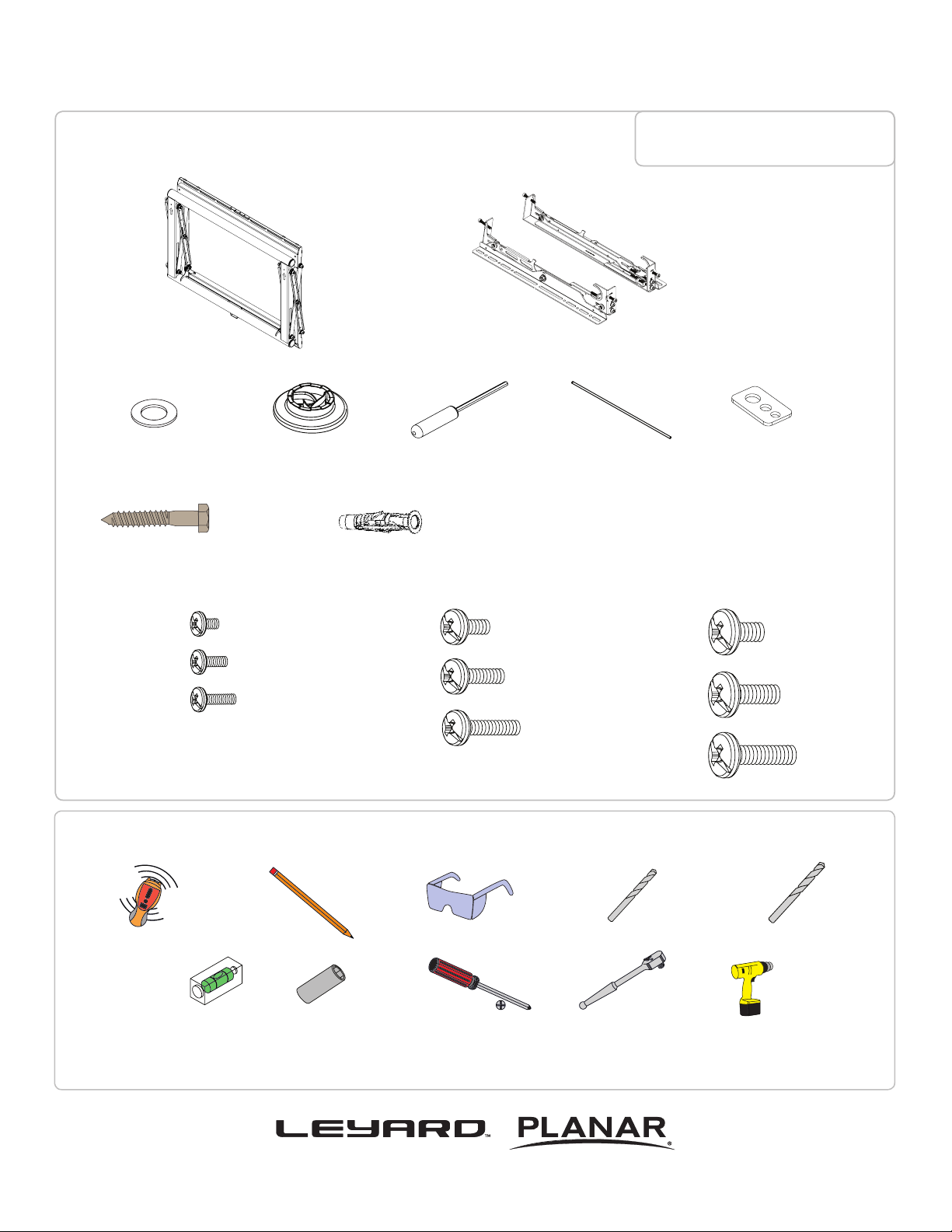
Included Components
5/16” Flat Washers
(Qty 4)
5/16” x 3” Lag Bolts
(Qty 4)
Wall Mount
(Qty 1)
Universal Spacers
(Qty 8)
Finned Anchors
(Qty 4)
M5 Allen Driver
(Qty 1)
Maximum Flat Panel Weight:
160 lb. / 72.57 kg.
Thread Depth Indicator
(Qty 1)
Bracket
(Qty 1 Pair)
Universal Washers
(Qty 4)
M4 x 12mm (Qty 4)
M4 x 16mm (Qty 4)
M4 x 25mm (Qty 4)
M6 x 12mm (Qty 4)
M6 x 16mm (Qty 4)
M6 x 25mm (Qty 4)
Required for installation
Electronic Stud Finder M6 or 1/4” Drill Bit
Level
Pencil Protective Eyewear
13mm or 1/2” Socket
Phillips Head Screwdriver
Socket Wrench
M8 x 12mm (Qty 4)
M8 x 16mm (Qty 4)
M8 x 25mm (Qty 4)
3/8” Masonry Drill Bit
Portable Drill
Page 2
www.planar.com | Nor th Americ a Toll Free: 1-886 -475-2 627 | Direct: 1-503-748 -1100
Page 3
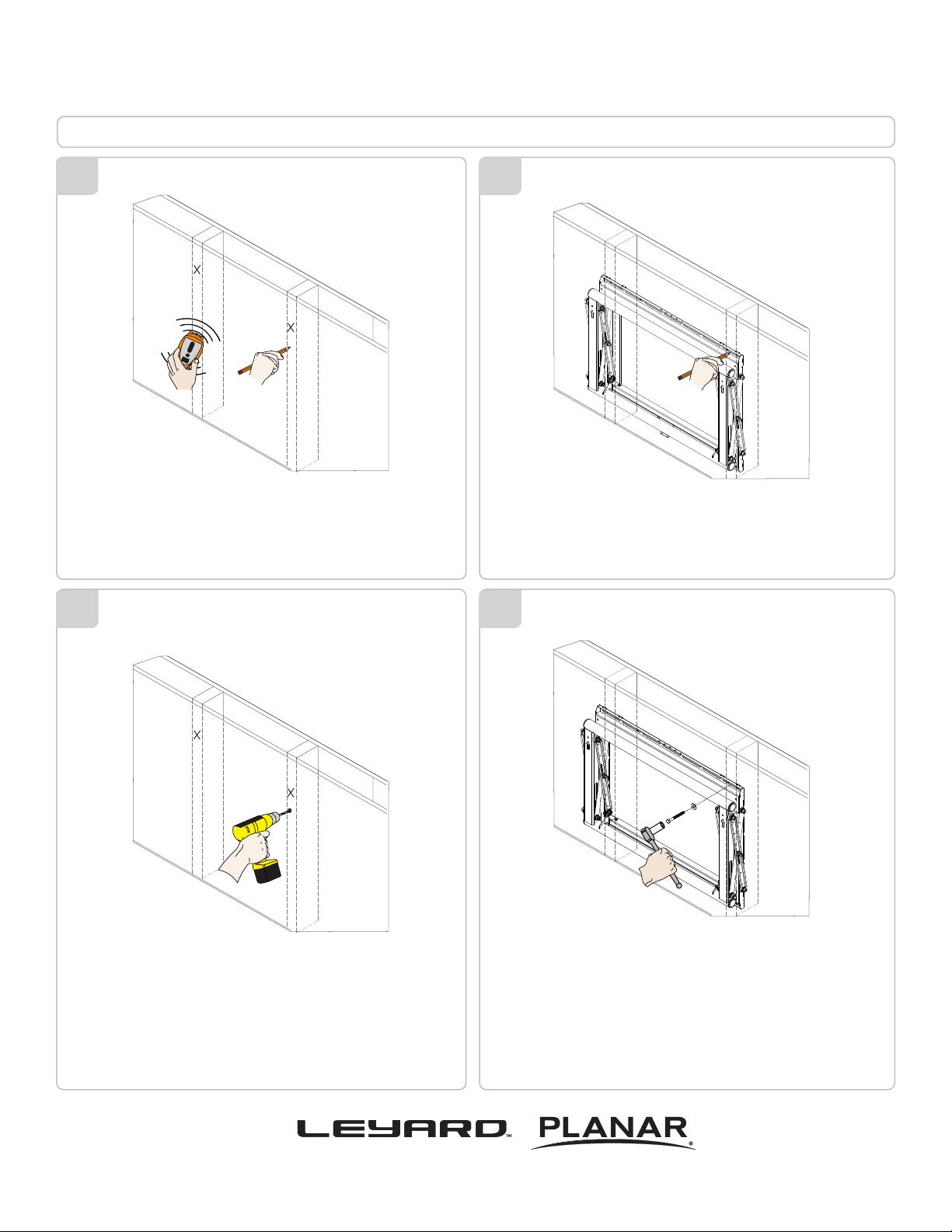
Wood Stud Installation
998-0368-00 - VMT-MXL
Installation Guide
1
1. Use a stud nder to determine the wall studs in
the vicinity of the mount.
2. Use a pencil to mark each of the wall studs.
3
2
Use a pencil to mark the upper right mounting location
of the wall stud.
4
Drill a pilot hole using a M6 or 1/4” drill bit on the
stud that was marked on the upper right.
www.planar.com | Nor th Americ a Toll Free: 1-886 -475-2 627 | Direct: 1-503-748 -1100
1. Place the mount against the wall and align it
with the pilot hole.
2. Insert one (1) 5/16” x 3” lag bolt one (1) 5/16”
washer into the upper right pilot hole.
3. Use a socket wrench and a 1/2” socket to
tighten the lag bolt.
4. Do not over tighten the lag bolt.
Page 3
Page 4
998-0368-00 - VMT-MXL
Installation Guide
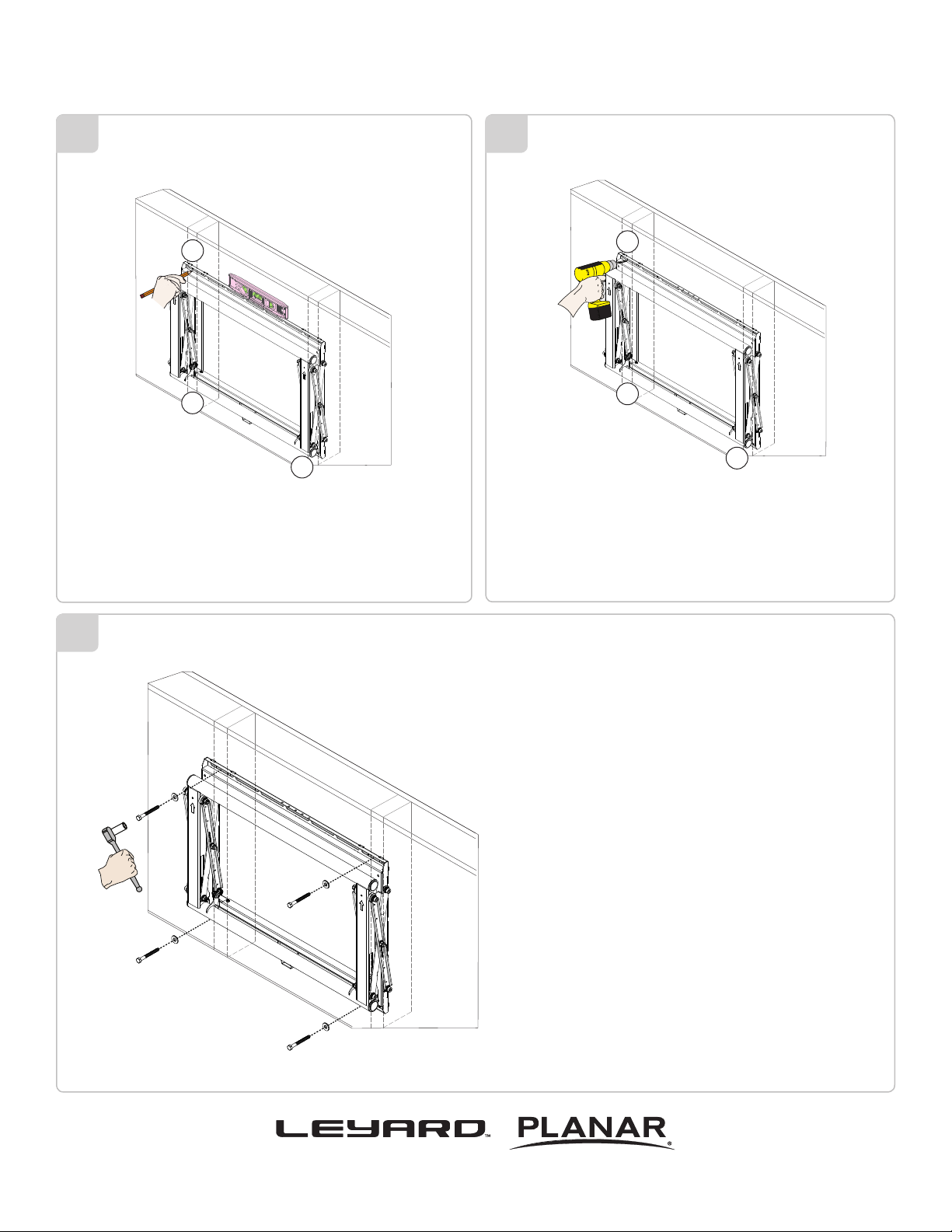
5
1
2
3
1. Level the mount
2. Use a pencil to mark the remaining three (3)
mounting locations
6
1
2
3
Drill a pilot hole in each of the three (3) marks with a
power drill and a M6 or 1/4” drill bit.
7
1. Insert one (1) 5/16” x 3” lag bolt and one (1) 5/16”
washer into each pilot hole.
2. Tighten all lag bolts using a socket wrench and
1/2” socket.
3. Do not over tighten the lag bolts
Page 4
www.planar.com | Nor th Americ a Toll Free: 1-886 -475-2 627 | Direct: 1-503-748 -1100
Page 5

Concrete Wall Installation
998-0368-00 - VMT-MXL
Installation Guide
8
1
2
3
4
Two people recommended for this step; one person
to level the mount and another person to mark the
mounting locations.
9
1
2
3
4
Drill a pilot hole in each of the four (4) mark areas
with a 3/8” masonry drill bit.
10
Insert the Finned anchors into each pilot holes.
Lightly tap each Finned anchors into place with a
hammer.
11
1. Insert one (1) 5/16” x 3” Lag Bolt and one (1) 5/16”
washer into each pilot holes.
2. Tighten all lag bolts using a socket wrench and
1/2” socket.
www.planar.com | Nor th Americ a Toll Free: 1-886 -475-2 627 | Direct: 1-503-748 -1100
Page 5
Page 6

998-0368-00 - VMT-MXL
Installation Guide
Installing OPTIONAL Model Specic Spacers
12
For ease of installation
Model-specic spacers are availible for most at-panel
displays. Engineered with the intent of signicantly reducing
installation tim on large video wall array. Contact Customer
Service to inquire about model specic spacers.
13
Level
1) Mount the VMT-MXL to the desired location.
2) Align and Level the spacer to the corner register tabs
of the mount.
Use commercially available hardware to secure the spacer.
Utilize the same spacer for multiple VMT-MXL installations.
For illustration only. VMT-MXL Spacer will vary.
14
Multiple VMT-MXL mounts can be installed using model specic
spacers. Simply repeat step one when installing each of the
surrounding VMT-MXL mounts. Use one spacer for each 2x2
installation by mounting it to the wall, or utilize the same spacer
as many times needed to complete an unlimited VMT-MXL large
matrix video wall.
1. Plumb and level and mark each corner where the VMT-MXL
will be mounted (or secure to the wall).
2. Install the second mount working in a horizontal direction.
3. Square, Level, and Plumb.
4. Repeat this step for each mount horizontally
Page 6
www.planar.com | Nor th Americ a Toll Free: 1-886 -475-2 627 | Direct: 1-503-748 -1100
Page 7

Selecting the Mounting Hardware
15
Marking the 1/8”
Allowance
Small Straw or Toothpick
998-0368-00 - VMT-MXL
Installation Guide
1) Insert a small straw or toothpick into the threaded inserts found
on the back of the at-panel.
2) Use a pencil to mark the depth of the threaded insert on the
small straw or toothpick.
3) Mark the straw or toothpick 1/8” above the depth of the
threaded insert, as shown in Figure 1.
4) Insert the small straw or toothpick into the remaining threaded
inserts to compare and verify their depth using the straw or
toothpick’s 1/8” allowance mark.
5) Locate the correct diameter screw for the threaded insert.
If the selected screw is longer than the 1/8” allowance mark
on the small straw or toothpick, as shown in Figure 2 and
Figure 3, do not use this screw. The screw length must not
bypass the mark.
6) Test each size of the screws provided.
The correct screws should thread easily into the mounting
point and not pull out when tension is applied.
Small Straw
or Toothpick
Depth Plus 1/8” Allowance
Mark
www.planar.com | Nor th Americ a Toll Free: 1-886 -475-2 627 | Direct: 1-503-748 -1100
Small Straw
or Toothpick
Depth Plus 1/8” Allowance
Mark
Page 7
Page 8

998-0368-00 - VMT-MXL
Installation Guide
16
Universal Washer Installation
M8
M5, M6
M4
Universal Washers are designed to accommodate the various
M4, M5, M6 and M8 hole sizes required by at-panels.
1) Place the at-panel screen-side down on a soft, at surface.
2) Identify the number and location of the thread inserts on the
back of the at-panel.
3) Aligning the holes on each mounting bracket with the thread
inserts on the back of your at-panel.
4) Secure each mounting bracket to the at-panel by inserting a
minimum of two (2) screws per bracket.
Do not over tighten the mounting hardware.
Make sure the directional arrows on the mounting brackets
are facing up.
17
Universal Spacer Installation
Mounting Screw
Universal Washer
Mounting Bracket
Flat Panel
Universal Spacer
Mount Point
Universal Spacers allow the user to attach the mounting bracket
to at-panels which have recessed or uneven mount points. Each
Universal Spacer adds 1/4” to the distance between the mounting
bracket and the at-panel.
The Universal Spacers must be stacked and oriented as
shown.
The Universal Spacers must only be installed between the
mounting bracket and the at-panel.
Page 8
www.planar.com | Nor th Americ a Toll Free: 1-886 -475-2 627 | Direct: 1-503-748 -1100
Page 9

998-0368-00 - VMT-MXL
Installation Guide
18
Attaching the Flat-Panel to the Mount
Mounting bracket adjustments are factory pre-set (see Note).
This section requires two people.
Do not release your at-panel until you are certain that top and
bottom hooks of both mounting brackets are securely seated
on the upper and lower mounting rails of the wall panel.
1) Raise the at-panel past the top and bottom mounting rails on the
wall panel.
2) Slide the at-panel down slowly, keeping it close to the wall.
3) Engage the top and bottom mounting brackets to the rails of the
mount.
Note: These registers must
align prior to installation.
They are factory set.
Check to determine proper
alignment
19
Locking Safety Screw Installation
Pre-installed
Locking Safety Screw
( 1 per Bracket )
The locking safety screws keep the at-panel from
being accidently dislodged from the VMT-MXL.
1) Locate the pre-installed security locking safety screw at
the bottom of each of the mounting brackets.
2) Use the M5 Allen driver (supplied) to tighten the locking
safety screw.
Do not overtighten the locking safety screws.
Note: Tighten screw to surface, then tighten 1/4” turn
ONLY TIGHTEN AFTER
FINAL ADJUSTMENT
www.planar.com | Nor th Americ a Toll Free: 1-886 -475-2 627 | Direct: 1-503-748 -1100
Page 9
Page 10

998-0368-00 - VMT-MXL
Installation Guide
MOVE INWARD
TOP
Left
Control
BOTTOM
MOVE OUTWARD
TOP
Left
Control
BOTTOM
TILT UP
TOP
BOTTOM
TOP
BOTTOM
Right
Control
Right
Control
TOP
BOTTOM
TILT DOWN
TOP
BOTTOM
TOP
BOTTOM
TOP
BOTTOM
AND/
OR
AND/
OR
TOP TOP
BOTTOM BOTTOM
TOP TOP
BOTTOM BOTTOM
Page 10
www.planar.com | Nor th Americ a Toll Free: 1-886 -475-2 627 | Direct: 1-503-748 -1100
Page 11

LEVEL UP
998-0368-00 - VMT-MXL
Installation Guide
Control
LEVEL
LEVEL DOWN
Control
LEVEL
ROTATE LEFT
Left
Left
Right
Control
LEVEL
Right
Control
LEVEL
Left
Control
LEVEL
ROTATE RIGHT
Left
Control
LEVEL
Right
Control
LEVEL
Right
Control
LEVEL
www.planar.com | Nor th Americ a Toll Free: 1-886 -475-2 627 | Direct: 1-503-748 -1100
Page 11
Page 12

998-0368-00 - VMT-MXL
Installation Guide
20
Use the GAPit GO/No Go Gauge (supplied with model specific spacer) as a final step in the process
to inspect and adjust the gap to prevent costly replacement and extend the lifespan of the displays.
Damage happens when weight is transferred to the ultra-thin bezels of video wall installations,
if the recommended gap specications of .050” is not maintained vertically and horizontally.
This results in image distortion, and costly repairs and replacement
1. Swipe GAPit along vertical gap
2. Inspect for .050” gap & adjust if
needed
3. Swipe GAPit along horizontal gap
4. Inspect for .050” gap & adjust if
needed
Page 12
www.planar.com | Nor th Americ a Toll Free: 1-886 -475-2 627 | Direct: 1-503-748 -1100
Page 13

998-0368-00 - VMT-MXL
Installation Guide
21
Servicing
1. Push evenly in the front of the VMT-MXL to release
the single latch spring lock (Figure 1).
2. Slowly pull the front of the VMT-MXL to extend the
scissor arms (Figure 2).
3. Loosen the locking safety screws on both mounting
brackets.
4. Tilt up the bottom of the at-panel, then set their
kickstands against the bottom tubing of the mount
(Figures 2 & 3).
5. Perform any neccessary repairs. Close the latch
after servicing.
Figure 1
Single Latch Spring Lock
Figure 2
Figure 3
www.planar.com | Nor th Americ a Toll Free: 1-886 -475-2 627 | Direct: 1-503-748 -1100
Page 13
 Loading...