

Page 1

Planar UltraRes Series
RS232 User Manual
Page 2

Copyright © 12 Mar 2016 by Planar Systems, Inc. All rights reserved.
Contents of this publication may not be reproduced in any form without permission of Planar
Systems, Inc.
Trademark Credits
Windows™ is a trademark of Microsoft Corp.
All other companies are trademarks or registered trademarks of their respective companies.
Disclaimer
The information contained in this document is subject to change without notice. Planar
Systems, Inc. makes no warranty of any kind with regard to this material. While every
precaution has been taken in the preparation of this manual, the Company shall not be liable
for errors or omissions contained herein or for incidental or consequential damages in
connection with the furnishing, performance, or use of this material.
Warranty and Service Plans
Planar warranty and service plans will help you maximize your investment by providing great
support, display uptime, and performance optimization. From post-sale technical support to
a full suite of depot services, our services are performed by trained Planar employees. When
you purchase a Planar product, you get more than a display, you get the service and support
you need to maximize your investment. To find the latest warranty and service information
regarding your Planar product, please visit http://www.planar.com/support
RoHS Compliance Statement
The Planar UltraRes Series is fully RoHS compliant.
Part Number: 020-1298-00B
Page 3

Contents
RS232 Communication. . . . . . . . . . . . . . . . . . . . . . . . . . . . . . . . . . . . . . . . . . . . . . . . . . . . . . . . . . . . . . . . . . . . . . . . . . . . .5
Applicable Models . . . . . . . . . . . . . . . . . . . . . . . . . . . . . . . . . . . . . . . . . . . . . . . . . . . . . . . . . . . . . . . . . . . . . . . . . . . . . . .5
RS232 Setup . . . . . . . . . . . . . . . . . . . . . . . . . . . . . . . . . . . . . . . . . . . . . . . . . . . . . . . . . . . . . . . . . . . . . . . . . . . . . . . . . . . . .5
Connecting the RS232 Cable. . . . . . . . . . . . . . . . . . . . . . . . . . . . . . . . . . . . . . . . . . . . . . . . . . . . . . . . . . . . . . . . . . . . . .5
RS232 Protocol . . . . . . . . . . . . . . . . . . . . . . . . . . . . . . . . . . . . . . . . . . . . . . . . . . . . . . . . . . . . . . . . . . . . . . . . . . . . . . . . . . .6
Command Structure . . . . . . . . . . . . . . . . . . . . . . . . . . . . . . . . . . . . . . . . . . . . . . . . . . . . . . . . . . . . . . . . . . . . . . . .6
Protocol Encoding . . . . . . . . . . . . . . . . . . . . . . . . . . . . . . . . . . . . . . . . . . . . . . . . . . . . . . . . . . . . . . . . . . . . . . . . . .7
Examples. . . . . . . . . . . . . . . . . . . . . . . . . . . . . . . . . . . . . . . . . . . . . . . . . . . . . . . . . . . . . . . . . . . . . . . . . . . . . . . . . . .7
RS232 Codes . . . . . . . . . . . . . . . . . . . . . . . . . . . . . . . . . . . . . . . . . . . . . . . . . . . . . . . . . . . . . . . . . . . . . . . . . . . . . . . . . . . . .9
Current Zone Layout. . . . . . . . . . . . . . . . . . . . . . . . . . . . . . . . . . . . . . . . . . . . . . . . . . . . . . . . . . . . . . . . . . . . . . 27
Key. . . . . . . . . . . . . . . . . . . . . . . . . . . . . . . . . . . . . . . . . . . . . . . . . . . . . . . . . . . . . . . . . . . . . . . . . . . . . . . . . . . . . . . 28
Timezone . . . . . . . . . . . . . . . . . . . . . . . . . . . . . . . . . . . . . . . . . . . . . . . . . . . . . . . . . . . . . . . . . . . . . . . . . . . . . . . . 30
Sending Serial Commands via USB . . . . . . . . . . . . . . . . . . . . . . . . . . . . . . . . . . . . . . . . . . . . . . . . . . . . . . . . . . . . . . 34
Installing the UltraRes USB drivers. . . . . . . . . . . . . . . . . . . . . . . . . . . . . . . . . . . . . . . . . . . . . . . . . . . . . . . . . 34
Using the UltraRes USB Connection . . . . . . . . . . . . . . . . . . . . . . . . . . . . . . . . . . . . . . . . . . . . . . . . . . . . . . . 40
Sending RS232 Commands Via TCP or UDP. . . . . . . . . . . . . . . . . . . . . . . . . . . . . . . . . . . . . . . . . . . . . . . . . . . . . . 41
Planar UltraRes Series RS232 User Manual iii
Page 4

Table of Contents
iv Planar UltraRes Series RS232 User Manual
Page 5
RS232 Communication
RS232 control is not necessary for operation, but is a convenient way to control
Planar® UltraRes™ Series displays from a computer at a distance. Most things you can
do with the remote, you can do with RS232 commands. Plus, you can send inquiries
to the displays and find out the current settings and values. RS232 connections are
made with standard straight-through cables.
Note: Serial communication can occur over RS232, USB-B or LAN.
Applicable Models
This RS-232 user manual applies to all UltraRes models with the exception of the
UR8450 and UR9850 models. The RS232 instructions for the UR8450 and UR9850
models can be found in the User Manual for these models, located at
www.planar.com/support/.
RS232 Setup
The RS232 connection must use the following settings:
• 19200 baud rate
• 8 data bits
• 1 stop bit
• No parity bit
• No HW (RTS/CTS) or SW (XON/XOFF) flow control
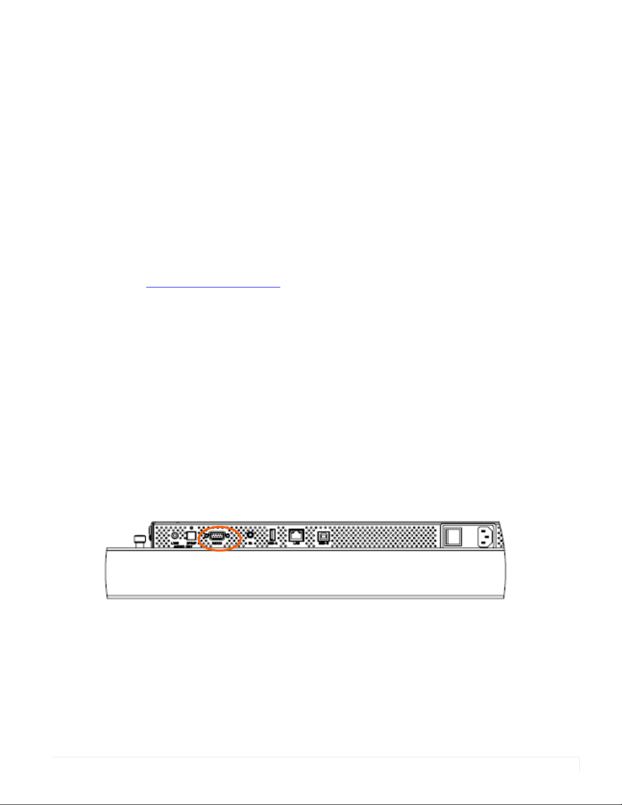
Connecting the RS232 Cable
The RS232 cable will connect to a PC or control system, depending on your setup.
Planar UltraRes Series RS232 User Manual 5
Page 6

RS232 Protocol
RS232 Protocol
Command Structure
[OPCODE](MODIFIERS)[OPERATOR][OPERANDS][TERM]
• OPCODE is the command code (e.g. “GAIN”). This can be written either using the
• MODIFIERS are modifier values [e.g. “(ZONE.1, ALL)”]. There are zero or more
• OPERATOR is the action to be performed. See the “Operators” column in the
named command code (see the “Command Code” column in the table) or the
numeric command code (see the “Numeric Command Code” column in the
table).
modifiers for each command. The modifiers can be written either with their
named value or their numeric value (see "Examples" on page 7). See the
“Modifiers” column in the table.
table.
• ‘=’ writes the setting value.
• ‘?’ reads the setting value in name form (see "Examples" on page 7).
• ‘#’ reads the setting value in numeric form (see "Examples" on page 7).
• ‘+’ increments the setting value.
• ‘-‘ decrements the setting value.
• ‘:’ indicates that the message is a response to one of the following operators:
=?#+-
• ‘!ERR’ indicates that the message is a failure response. An error code will be
listed after the “ERR”, with a space before it. Error codes are as follows:
• ERR 1: Invalid syntax
• ERR 2: [Reserved for future use]
• ERR 3: Command not recognized
• ERR 4: Invalid modifier
• ERR 5: Invalid operands
• ERR 6: Invalid operator
• ‘@ACK’ indicates that the message is an acknowledgment (ACK) to a
command that has no operator.
• ‘^NAK’ indicates that the message is a negative acknowledgment (NAK) to a
command that has no operator. This indicates that the command was
received but cannot be processed at this time.
• [No operator] denotes an action. In this case, there’s no operator and no
operand.
6 Planar UltraRes Series RS232 User Manual
Page 7
Protocol Encoding
Protocol Encoding
• OPERAND indicates the data to be sent with the message. In some cases, there
can be multiple operands. See the “Operands” column in the table.
• Enumerated operands can be written either with their named value or their
numeric value (see "Examples" on page 7).
• String operands are written with quotation marks at the beginning and end.
Example: “this is a string operand”.
• Integer (or signed integer / unsigned integer) are always numeric values.
• Note that enumerated and integer values can be written either in decimal or
hexadecimal. For example, a decimal value of ‘50’ can be written in
hexadecimal as ‘0x32’.
• TERM is the termination character for the command. This can either be the
ASCII carriage return character (0x0D) or a semicolon. The response will use the
same termination character.
• All parts of the command structure are case insensitive (e.g. “BRIGHTNESS”,
“brightness” and BrIgHtNeSs” are all the same). Responses will always be in
capital letters.
• Excessive white space is allowed (e.g. “BRIGHTNESS=50”, “BRIGHTNESS = 50”
and “BRIGHTNESS = 50” are all the same).
• Modifiers and operands can be separated by commas, spaces or both (e.g.
“GAIN=100,100,100”, “GAIN=100 100 100” and “GAIN=100, 100, 100” are all the
same). Responses will always separate with one space between modifiers and
operands).
Examples
Note: [CR] is the ASCII carriage return character (0x0D).
Command Response Notes
brightness = 100 [CR] BRIGHTNESS:100 [CR] Sets the Brightness value to 100
brightness = 100; BRIGHTNESS:100; Also sets the Brightness value to 100,
but uses the ‘;’ termination character
instead of [CR]. The response uses the
same termination character.
200=100 [CR] 200:100 [CR] “200” is the numeric command code for
“BRIGHTNESS”
brightness+ [CR] BRIGHTNESS:101 [CR] Increments the current Brightness
value
brightness- [CR] BRIGHTNESS:100 [CR] Decrements the current Brightness
value
Planar UltraRes Series RS232 User Manual 7
Page 8

Examples
Command Response Notes
gain = 101 102 103 [CR] GAIN:101 102 103 [CR] Example command with multiple
operators (sets Red Gain to 101, Green
Gain to 102 and Blue Gain to 103, on
the current zone)
gain(red)+ GAIN(RED):102 Increments the Red Gain on the current
zone
gain(zone.1, all) = 104,105,106 GAIN(ZONE.1 ALL):104 105 106 Example command with multiple
modifiers, multiple operators and
different separators between the
modifiers and operators (sets Red Gain
to 104, Green Gain to 105 and Blue
Gain to 106, on Zone 1)
ipv4.address(static)=”10.15.0.220” [CR] IPV4.ADDRESS(STATIC)=”10.15.0.220”
[CR]
reset(user) [CR] RESET(USER)@ACK [CR] Example action command (no operator
reset(user) [CR] RESET(USER)^NAK [CR] Example action command that cannot
aspect? [CR] ASPECT:AUTO [CR] The name for the Aspect Ratio setting
Example command with a string
operator
or operand)
be processed at this time
value is returned
aspect# [CR] ASPECT:0 [CR] The number for the Aspect Ratio
setting value is returned
aspect=fill [CR] ASPECT:FILL [CR] Sets the Aspect Ratio to Fill
aspect=3 [CR] ASPECT:3 [CR] Also sets the Aspect Ratio to Fill
brightness @@ [CR] BRIGHTNESS!ERR 1 [CR] Example of an invalid syntax (“@@” isn’t
a valid operator)
fake.command = 1 [CR] FAKE.COMMAND:ERR 3 [CR] Example of an invalid opcode
(“FAKE.COMMAND” doesn’t exist)
brightness(zone.999) = 100 [CR] BRIGHTNESS(ZONE.999)!ERR 4 [CR] Example of an invalid modifier
(“ZONE.999” isn’t a valid modifier for
“BRIGHTNESS”)
brightness=”new value” [CR] BRIGHTNESS!ERR 5 [CR] Example of an invalid operand (the
Brightness command doesn’t accept a
string operand)
model.id = 1 [CR] MODEL.ID!ERR 6 [CR] Example of an invalid operator (cannot
write to this command)
8 Planar UltraRes Series RS232 User Manual
Page 9
RS232 Codes
Notes:
RS232 Codes
• The examples are written with the command first and the response in italics.
Example:
• Command: ASPECT(ZONE.1)=AUTO
• Response: ASPECT(ZONE.1):AUTO
• In many instances, a modifier may be omitted and the display will replace it
with a default value. For example, the default modifier for the ASPECT
command is CURRENT, so the following two commands are identical:
• ASPECT(CURRENT)=AUTO
•ASPECT=AUTO
Setting
Command
Code
Modifiers Operands
Operators
Numeric Command Code
Allow Pop
Up
Messages
Aspect Ratio ASPECT 500 =?+- Zone
Audio Input AUDIO.INPUT 1003 ? Source
Audio Select AUDIO.ZONE 1007 =?+- Zone
OSD.ALLOW.
POPUP
1300 =?+- 0 = NO
0 = ZONE.1
1 = ZONE.2
2 = ZONE.3
3 = ZONE.4
253 =
ALL.INPUT
254 = ALL
254 =
ALL.ZONE
255 =
CURRENT
[None =
CURRENT]
1 = YES
0 = AUTO
1 = 16X9
2 = 4X3
3 = FILL
4 = NATIVE
5 = LETTERBOX
0 = OPS
1 = HDMI.1
2 = HDMI.2
3 = HDMI.3
4 = HDMI.4
5 = DP
0 = ZONE.1
1 = ZONE.2
2 = ZONE.3
3 = ZONE.4
Example Notes
Available in Standby
No OSD.ALLOW.POPUP=YES
OSD.ALLOW.POPUP:YES
No [For Zone 1]
ASPECT(ZONE.1)=AUTO
ASPECT(ZONE.1):AUTO
[For the current zone]
ASPECT=16X9
ASPECT:16X9
No AUDIO.INPUT?
AUDIO.INPUT:HDMI.1
No AUDIO.ZONE=ZONE.1
AUDIO.ZONE:ZONE.1
See Main -> Advanced
Settings -> Menus and
Messages -> Allow Pop Up
Messages
See Main -> Image Adjust ->
Aspect Ratio
Returns the input source in the
zone currently playing audio,
as chosen by Audio Select
See Main -> Audio -> Audio
Select
Planar UltraRes Series RS232 User Manual 9
Page 10
RS232 Codes
Setting
Command
Code
Modifiers Operands
Example Notes
Operators
Available in Standby
Numeric Command Code
Audio
Settings
Auto Power OnAUTO.ON 1407 =?+- 0 = OFF
Auto Scan
Sources
Backlight
Intensity
Balance AUDIO.BALANCE 1000 =?+- 0-100 No AUDIO.BALANCE=50
Bass AUDIO.BASS 1001 =?+- 0-100 No AUDIO.BASS=50
Blank Screen
Color
Brightness BRIGHTNESS 200 =?+- Zone
AUDIO.SETTINGS 1009 =? Op 1: Zone
SOURCE.SCAN 105 =?+- 0 = OFF
BACKLIGHT.
INTENSITY
BLANK.COLOR 1306 =?+- 0 = RED
1400 =?+- 1-100 No BACKLIGHT.INTENSITY=75
0 = ZONE.1
1 = ZONE.2
2 = ZONE.3
3 = ZONE.4
253 =
ALL.INPUT
254 = ALL
254 =
ALL.ZONE
255 =
CURRENT
[None =
CURRENT]
0 = ZONE.1
1 = ZONE.2
2 = ZONE.3
3 = ZONE.4
Ops 2-8:
Unsigned
Integers
1 = ON
1 = ON
1 = GREEN
2 = BLUE
3 = CYAN
4 = MAGENTA
5 = YELLOW
6 = WHITE
7 = BLACK
0-100 No [For Zone 1]
No [For Zone 3, Volume=51, Treble=52,
Bass=53, Balance=54, Mute Off, Internal
Speakers On]
AUDIO.SETTINGS=2 51 52 53 54 0 1
AUDIO.SETTINGS:2 51 52 53 54 0 1
Yes AUTO.ON=ON
AUTO.ON:ON
No SOURCE.SCAN=ON
SOURCE.SCAN:ON
BACKLIGHT.INTENSITY:75
AUDIO.BALANCE:50
AUDIO.BASS:50
No BLANK.COLOR=BLUE
BLANK.COLOR:BLUE
BRIGHTNESS(ZONE.1)=50
BRIGHTNESS(ZONE.1):50
[For the current zone]
BRIGHTNESS=55
BRIGHTNESS:55
Values are set/returned in the
order AUDIO.ZONE,
AUDIO.VOLUME,
AUDIO.TREBLE, AUDIO.BASS,
AUDIO.BALANCE,
AUDIO.MUTE,
AUDIO.SPEAKERS
See Main -> Advanced
Settings -> Power -> Auto
Power On
See Main -> Inputs and
Views -> Auto Scan Sources
See Main -> Advanced
Settings -> Backlight ->
Backlight Intensity
See Main -> Audio -> Balance
See Main -> Audio -> Bass
See Main -> Advanced
Settings -> Menus and
Messages -> Blank Screen
Color
See Main -> Image Adjust ->
Brightness
10 Planar UltraRes Series RS232 User Manual
Page 11
RS232 Codes
Setting
Command
Code
Modifiers Operands
Operators
Numeric Command Code
Color COLOR 202 =?+- Zone
Color Space COLORSPACE 207 =?+- Mod 1: Zone
0 = ZONE.1
1 = ZONE.2
2 = ZONE.3
3 = ZONE.4
253 =
ALL.INPUT
254 = ALL
254 =
ALL.ZONE
255 =
CURRENT
[None =
CURRENT]
0 = ZONE.1
1 = ZONE.2
2 = ZONE.3
3 = ZONE.4
253 =
ALL.INPUT
254 = ALL
254 =
ALL.ZONE
255 =
CURRENT
Available in Standby
0-100 No [For Zone 1]
0 = REC601
1 = REC709
2 = RGB
3 = RGB.VIDEO
4 = AUTO
No [Setting Color Space for Zone 1]
COLOR(ZONE.1)=50
COLOR(ZONE.1):50
[For the current zone]
COLOR=55
COLOR:55
COLORSPACE(ZONE.1, SETTING)=REC709
COLORSPACE(ZONE.1 SETTING):REC 709
[Setting Color Space for the current zone]
COLORSPACE(CURRENT, SETTING)=AUTO
COLORSPACE(CURRENT SETTING):AUTO
[Reading the actual Color Space for the
current zone]
COLORSPACE(CURRENT, ACTUAL)?
COLORSPACE(CURRENT ACTUAL):RGB
Example Notes
See Main -> Image Adjust ->
Color
“Setting” is the value that the
color space is set to. See
Main -> Image Adjust -> Color
Space.
“Actual” is the currently
applied color space (cannot
return AUTO). See Main ->
Information -> Image
Information -> Color Space.
Color Subsampling
Color
Temperature
COLOR.
SUBSAMPLING
COLOR.
TEMPERATURE
Mod 2: Value
Type
0 = SETTING
1 = ACTUAL
301 ? Zone
0 = ZONE.1
1 = ZONE.2
2 = ZONE.3
3 = ZONE.4
255 =
CURRENT
208 =?+- Zone
0 = ZONE.1
1 = ZONE.2
2 = ZONE.3
3 = ZONE.4
253 =
ALL.INPUT
254 = ALL
254 =
ALL.ZONE
255 =
CURRENT
String No [For Zone 1]
0 = 3200K
1 = 5500K
2 = 6500K
3 = 7500K
4 = 9300K
5 = NATIVE
No [For Zone 1]
COLOR.SUBSAMPLING(ZONE.1)?
COLOR.SUBSAMPLING(ZONE.1):"4:4:4"
[For the current zone]
COLOR.SUBSAMPLING?
COLOR.SUBSAMPLING:"4:2:0"
COLOR.TEMPERATURE(ZONE.1)=6500K
COLOR.TEMPERATURE(ZONE.1):6500K
[For the current zone]
COLOR.TEMPERATURE=NATIVE
COLOR.TEMPERATURE=NATIVE
See Main -> Information ->
Image Information -> Color
Subsampling
See Main -> Image Adjust ->
Color Temperature
Planar UltraRes Series RS232 User Manual 11
Page 12
RS232 Codes
Setting
Command
Code
Modifiers Operands
Operators
Numeric Command Code
Contrast CONTRAST 201 =?+- Zone
Current
Zone
Current
Zone Layout
CURRENT.ZONE 100 =?+- Zone
CURRENT.ZONE.
LAYOUT
108 ? 0 = S.1
0 = ZONE.1
1 = ZONE.2
2 = ZONE.3
3 = ZONE.4
253 =
ALL.INPUT
254 = ALL
254 =
ALL.ZONE
255 =
CURRENT
[None =
CURRENT]
Available in Standby
0-100 No [For Zone 1]
No CURRENT.ZONE=ZONE.1
0 = ZONE.1
1 = ZONE.2
2 = ZONE.3
3 = ZONE.4
No CURRENT.ZONE.LAYOUT?
1 = P.UL.1
2 = P.UL.2
3 = P.UR.1
4 = P.UR.2
5 = P.LL.1
6 = P.LL.2
7 = P.LR.1
8 = P.LR.2
9 = D.L.1
10 = D.L.2
11 = D.T.1
12 = D.T.2
13 = T.L.1
14 = T.L.2
15 = T.L.3
16 = T.R.1
17 = T.R.2
18 = T.R.3
19 = T.T.1
20 = T.T.2
21 = T.T.3
22 = T.B.1
23 = T.B.2
24 = T.B.3
25 = T.M.1
26 = T.M.2
27 = T.M.3
28 = Q.1
29 = Q.2
30 = Q.3
31 = Q.4
CONTRAST(ZONE.1)=50
CONTRAST(ZONE.1):50
[For the current zone]
CONTRAST=55
CONTRAST:55
CURRENT.ZONE:ZONE.1
CURRENT.ZONE.LAYOUT:Q.1
Example Notes
See Main -> Image Adjust ->
Contrast
See Main -> Image Adjust ->
Current Zone
See separate table on page 27
for operands
12 Planar UltraRes Series RS232 User Manual
Page 13
RS232 Codes
Setting
Command
Code
Modifiers Operands
Operators
Numeric Command Code
Default
Gateway
DHCP NETWORK.DHCP 1207 =? 0 = OFF
Diagnostic
Color
Display
Power
DisplayPort
Type
DNS Server 1 NETWORK.DNS1 1212 =? 0 = STATIC
DNS Server 2 NETWORK.DNS2 1213 =? 0 = STATIC
IPV4.GATEWAY 1206 =? 0 = STATIC
DIAGNOSTIC.
COLOR
DISPLAY.POWER 1408 =?+- 0 = OFF
DP.TYPE 1904 =?+- 0 = 1.1
206 =?+- Zone
[None =
Current (for
reads only]
[None =
STATIC (for
writes only]
0 = ZONE.1
1 = ZONE.2
2 = ZONE.3
3 = ZONE.4
253 =
ALL.INPUT
254 = ALL
254 =
ALL.ZONE
255 =
CURRENT
[None =
CURRENT]
[None =
Current (for
reads only]
[None =
STATIC (for
writes only]
[None =
Current (for
reads only]
[None =
STATIC (for
writes only]
String Yes [Read the current default gateway value]
1 = ON
0 = RED
1 = GREEN
2 = BLUE
255 = OFF
1 = ON
1 = 1.2
String Yes [Read the current DNS server 1 value]
String Yes [Read the current DNS server 2 value]
Example Notes
Available in Standby
IPV4.GATEWAY?
IPV4.NETMASK:"10.15.0.1"
[Write the default gateway for static IP]
IPV4.NETMASK(STATIC)="192.168.12.1"
IPV4.NETMASK(STATIC):"192.168.12.1"
Yes NETWORK.DHCP=ON
NETWORK.DHCP:ON
No [For Zone 1]
DIAGNOSTIC.COLOR(ZONE.1)=OFF
DIAGNOSTIC.COLOR(ZONE.1 ):OFF
[For the current zone]
DIAGNOSTIC.COLOR=BLUE
DIAGNOSTIC.COLOR:BLUE
Yes DISPLAY.POWER=ON
DISPLAY.POWER:ON
No DP.TYPE=1.2
DP.TYPE:1.2
NETWORK.DNS1?
NETWORK.DNS1:"172.16.0.140"
[Write the DNS server 1 for static IP]
NETWORK.DNS1(STATIC)="8.8.8.8"
NETWORK.DNS1(STATIC):"8.8.8.8"
NETWORK.DNS2?
NETWORK.DNS2:"172.16.0.191"
[Write the DNS server 2 for static IP]
NETWORK.DNS2(STATIC)="8.8.4.4"
NETWORK.DNS2(STATIC):"8.8.4.4"
See Main -> Advanced
Settings -> Network -> Default
Gateway
See Main -> Advanced
Settings -> Network -> DHCP
See Main -> Image Adjust ->
Diagnostic Color
See the IR remote control keys
ON and OFF
See Main -> Advanced
Settings -> System Settings ->
DisplayPort Type
See Main -> Advanced
Settings -> Network -> DNS
Server
Selects a secondary DNS
server
Planar UltraRes Series RS232 User Manual 13
Page 14

RS232 Codes
Setting
Command
Code
Modifiers Operands
Operators
Numeric Command Code
EDID Timing EDID.TIMING 400 =?+-! Mod 1: Input
EDID Zone EDID.SELECTEDCO
Enable
Internal
Speakers
Enable
Status LED
Error Log ERROR.LOG 2311 ? Log Entry
NNECTOR
AUDIO.SPEAKERS 1004 =?+- 0 = OFF
LED.ENABLE 1902 =? 0 = DISABLE
401 =?+- 0 = OPS
0 = OPS
1 = HDMI.1
2 = HDMI.2
3 = HDMI.3
4 = HDMI.4
5 = DP
6 = ALL
Mod 2:
Param
0 = UPDATE
1 = HACTIVE
2 = VACTIVE
3 = VREFRESH
4 =
FULL.SPEC
5 = PCLK
6 = HBLANK
7 = HFP
8 = HSYNC
9 = VBLANK
10 = VFP
11 = VSYNC
12 =
FACTORY
13 = TYPE
Number
1-65535
Signed Integer
-3 = 4K60
-2 = 4K30
-1 = 1080P
1 = HDMI.1
2 = HDMI.2
3 = HDMI.3
4 = HDMI.4
5 = DP
6 = ALL
1 = ON
1 = ENABLE
Example Notes
Available in Standby
No [Read the EDID type for HDMI 1]
EDID.TIMING(HDMI.1, TYPE)?
EDID.TIMING(HDMI.1 TYPE):4K60
[Set the HDMI 2 EDID horizontal active to
3840]
EDID.TIMING(HDMI.2, HACTIVE)=3840
EDID.TIMING(HDMI.2 HACTIVE):3840
[Update the HDMI 2 EDID]
EDID.TIMING(HDMI.2, UPDATE)
EDID.TIMING(HDMI.2 UPDATE)@ACK
No EDID.SELECTEDCONNECTOR=HDMI.1
EDID.SELECTEDCONNECTOR:HDMI.1
No AUDIO.SPEAKERS=ON
AUDIO.SPEAKERS:ON
Yes LED.ENABLE=ENABLE
LED.ENABLE:ENABLE
No ERROR.LOG(1)?
ERROR.LOG(1):"Wed Sep 16 13:39:33 2015 CRIT- Power supply 2 issue"
See Main -> Advanced
Settings -> EDID
UPDATE modifier is the only
one that supports the action
operator
See Main -> Advanced
Settings -> EDID -> Selected
Connector
See Main -> Audio -> Enable
Internal Speakers
See Main -> Advanced
Settings -> System Settings ->
Enable Status LED
Lists any faults that have
occurred in the system. Entry
#1 is the most recent. An
empty string returned means
that there are no more error
log entries after that entry.
14 Planar UltraRes Series RS232 User Manual
Page 15

RS232 Codes
Setting
Command
Code
Modifiers Operands
Operators
Numeric Command Code
Factory
Reset
Firmware
Update
Gain GAIN 209 =?+- Mod 1: Zone
RESET 2400 ! 0 = USER
1 =
FACTORY1
FIRMWARE.UPDATE 2200 =?! Mod 1:
Firmware
0 = AUTO
1 = VP.AP
2 = HDMI
Mod 2: Type
0 = START
1 = PACKET
2 = FINISH
3 = URL
0 = ZONE.1
1 = ZONE.2
2 = ZONE.3
3 = ZONE.4
253 =
ALL.INPUT
254 = ALL
254 =
ALL.ZONE
255 =
CURRENT
[None =
CURRENT]
Example Notes
Available in Standby
No RESET(USER)
String Yes FIRMWARE.UPDATE
For RED, GREEN
and BLUE
modifiers, one
operand:
0-200
For ALL
operand, three
operands:
Red Gain: 0-200
Green Gain: 0200
Blue Gain: 0-200
No [For red gain on Zone 1]
RESET(USER)@ACK
FIRMWARE.UPDATE(AUTO START)@ACK
GAIN(ZONE.1, RED)=100
GAIN(ZONE.1 RED):100
[For all three gains on the current zone: Red
Gain = 101, Green Gain = 102, Blue Gain =
103]
GAIN=101 102 103
GAIN=101 102 103
USER is the same as Main ->
Advanced Settings -> System
Settings -> Factory Reset.
FACTORY1 resets everything
that USER resets plus EDID
customizations, network
settings and presets.
See Main -> Advanced
Settings -> System Settings ->
Firmware Update
See Main -> Image Adjust ->
Red/Green/Blue Gain.
ALL modifier adjusts all three
gains at the same time.
The first modifier can only be
missing if both modifiers are
missing.
Mod 2: Color
0 = RED
1 = GREEN
2 = BLUE
255 = ALL
[None = ALL]
Planar UltraRes Series RS232 User Manual 15
Page 16

RS232 Codes
Setting
Command
Code
Modifiers Operands
Operators
Numeric Command Code
Gamma GAMMA 1504 =?+- Zone
Help HELP 2300 =? 0 = FIRST
0 = ZONE.1
1 = ZONE.2
2 = ZONE.3
3 = ZONE.4
253 =
ALL.INPUT
254 = ALL
254 =
ALL.ZONE
255 =
CURRENT
[None =
CURRENT]
2147483647
= NEXT
Example Notes
Available in Standby
0 = 1.5
1 = 1.55
2 = 1.6
3 = 1.65
4 = 1.7
5 = 1.75
6 = 1.8
7 = 1.85
8 = 1.9
9 = 1.95
10 = 2.0
11 = 2.05
12 = 2.1
13 = 2.15
14 = 2.2
15 = 2.25
16 = 2.3
17 = 2.35
18 = 2.4
19 = 2.45
20 = 2.5
21 = 2.55
22 = 2.6
23 = 2.65
24 = 2.7
25 = 2.75
26 = 2.8
String Yes [To get help on the OSD.STATUS command]
No [For Zone 1]
GAMMA(ZONE.1)=2.2
GAMMA(ZONE.1):2.2
[For the current zone]
GAMMA=2.5
GAMMA:2.5
HELP=OSD.STATUS
HELP:"OSD.STATUS
Numeric Value: 1308
Operators: ?
No Modifiers
1 Operand(s)
Operand #1: Unsigned Integer
DISABLE 0
ENABLE 1
OFF 0
ON 1
NO 0
YES 1
FALSE 0
TRUE 1
"
See Main -> Image Adjust ->
Gamma
Displays information for each
serial command.
To get a list of all serial
commands, first enter the
following command:
HELP(FIRST)?
Then enter the following
command continuously until it
returns NAK:
HELP(NEXT)?
16 Planar UltraRes Series RS232 User Manual
Page 17

RS232 Codes
Setting
Command
Code
Modifiers Operands
Example Notes
Operators
Available in Standby
Numeric Command Code
Host Name HOSTNAME 2403 =? String Yes [Read the current hostname value]
Image
Information
SIGNAL.INFO 300 ? Mod 1: Zone
0 = ZONE.1
1 = ZONE.2
2 = ZONE.3
3 = ZONE.4
255 =
CURRENT
[None =
CURRENT]
Mod 2:
Parameter
0 = HACTIVE
1 = VACTIVE
2 = PCLK
3 = HTOTAL
4 = VTOTAL
5 = VREFRESH
6 =
HREFRESH
7 =
INTERLACE
8 =
VFIELDRATE
9 =
VREFRESH.X.
100
10 =
COLORDEPTH
11 = TMDS
[None = ALL]
Unsigned
Integer
No SIGNAL.INFO(CURRENT, HACTIVE)?
HOSTNAME?
HOSTNAME:"UltraRes"
[Set the hostname to "My Display"]
HOSTNAME="My Display"
HOSTNAME:"My Display"
SIGNAL.INFO(CURRENT, HAC TIVE):1920
Sets the network hostname for
the display. Default string is
“UltraRes”.
See Main -> Information ->
Image Information
Planar UltraRes Series RS232 User Manual 17
Page 18

RS232 Codes
Setting
Command
Code
Modifiers Operands
Operators
Available in Standby
Numeric Command Code
Image
Position
IP Address IPV4.ADDRESS 1205 =? 0 = STATIC
IR Code IR.CODE 1210 =?+- 0-65535 Yes IR.CODE=12345
PAN 502 =?+- Mod 1: Zone
0 = ZONE.1
1 = ZONE.2
2 = ZONE.3
3 = ZONE.4
253 =
ALL.INPUT
254 = ALL
254 =
ALL.ZONE
255 =
CURRENT
Mod 2:
Direction
0 = X
1 = Y
255 = ALL
[None = ALL]
[None =
Current (for
reads only]
[None =
STATIC (for
writes only]
-1000 ~ 1000 No [For horizontal position on Zone 1]
PAN(ZONE.1, X)=0
PAN(ZONE.1, X):0
[For horizontal and vertical position on the
current zone: Horizontal Position = 10,
Vertical Position = 20]
PAN(CURRENT)=10 20
PAN(CURRENT)=10 20
String Yes [Read the current IP address value]
NETWORK.DNS1?
NETWORK.DNS1:"10.15.0.60"
[Write the DNS server 1 for static IP]
NETWORK.DNS1(STATIC)="192.168.12.12"
NETWORK.DNS1(STATIC):"192.168.12.12"
IR.CODE:12345
Example Notes
For the 'X' modifier, see
Main -> Image Adjust -> Image
Position -> Move Horizontal.
For the 'Y' modifier, see
Main -> Image Adjust -> Image
Position -> Move Vertical.
See Main -> Advanced
Settings -> Network -> IP
Address
See Menu -> Advanced
Settings -> System Settings ->
IR Remote ID Code
IR Remote
Lock
Key KEY 1200 = [See separate
Keypad Lock KEY.LOCK 1201 =? 0 = DISABLE
Layout LAYOUT 103 =?+- Multi-Source
IR.LOCK 1202 =? 0 = DISABLE
View
1 = DUAL
2 = TRIPLE
4 = PIP
5 = CURRENT
[None =
CURRENT]
1 = ENABLE
table]
1 = ENABLE
0 = SINGLE
1 = PIP.UL
2 = PIP.UR
3 = PIP.LL
4 = PIP.LR
5 = DUAL.L
6 = DUAL.T
7 = TRIPLE.L
8 = TRIPLE.R
9 = TRIPLE.T
10 = TRIPLE.B
11 = TRIPLE.M
12 = QUAD
Yes IR.LOCK=ENABLE
Yes [To send the MENU key]
Yes KEY.LOCK=ENABLE
No [To change the Dual layout to top-and-
18 Planar UltraRes Series RS232 User Manual
IR.LOCK:ENABLE
KEY=MENU
KEY:MENU
KEY.LOCK:ENABLE
bottom]
LAYOUT(DUAL)=DUAL.T
LAYOUT(DUAL):DUAL.T
[To change the PIP position to top left and
immediately apply the Multi-Source View
and layout]
LAYOUT=PIP.UL
LAYOUT:PIP.UL
See Menu -> Advanced
Settings -> System Settings ->
IR Remote Lock
See separate table on page 28
for key codes
See Menu -> Advanced
Settings -> System Settings ->
Keypad Lock
See Main -> Inputs and
Views -> Multi-Source View
See Main -> Inputs and
Views -> Multi-Source View ->
Advanced Layouts
Page 19

RS232 Codes
Setting
Command
Code
Modifiers Operands
Operators
Available in Standby
Numeric Command Code
Local
Dimming
MAC
Address
MEMC MEMC.LEVEL 1503 =?+- 0 = OFF
Menu
Position
Model ID MODEL.ID 2306 ? String No MODEL.ID?
Multi-Source
View
Mute AUDIO.MUTE 1002 =?+- 0 = OFF
Network
Ping
Next Source SOURCE.NEXT 104 ! Zone
LOCAL.DIMMING 1415 =?+- 0 = OFF
1 = ON
NETWORK.MAC 1203 ? String Yes NETWORK.MAC?
1 = LOW
2 = MEDIUM
3 = HIGH
OSD.POSITION 1301 =?+- 0 = CENTER
1 = UPPER.LEFT
2 =
UPPER.RIGHT
3 = LOWER.LEFT
4 =
LOWER.RIGHT
MULTI.VIEW 102 =?+- 0 = SINGLE
1 = DUAL
2 = TRIPLE
3 = QUAD
4 = PIP
1 = ON
NETWORK.PING 1211 = String Yes NETWORK.PING="www.google.com"
0 = ZONE.1
1 = ZONE.2
2 = ZONE.3
3 = ZONE.4
254 = ALL
255 =
CURRENT
No LOCAL.DIMMING=ON
LOCAL.DIMMING:ON
NETWORK.MAC="12:34:56:AB:CD:EF"
No MEMC.LEVEL=LOW
MEMC.LEVEL:LOW
No OSD.POSITION=CENTER
OSD.POSITION:CENTER
MODEL.ID="UR8451"
No MULTI.VIEW=QUAD
MULTI.VIEW:QUAD
No AUDIO.MUTE=ON
AUDIO.MUTE:ON
NETWORK.PING:"SUCCESS"
No [For Zone 1]
SOURCE.NEXT(ZONE.1)
SOURCE.NEXT(ZONE.1)@ACK
[For the current zone]
SOURCE.NEXT
SOURCE.NEXT@ACK
Example Notes
See Main -> Advanced
Settings -> Backlight -> Local
Dimming
See Main -> Advanced
Settings -> Network -> MAC
Address
See Main -> Advanced
Settings -> System Settings ->
MEMC
See Main -> Advanced
Settings -> Menus and
Messages -> Menu Position
See Main -> Information ->
System Information -> Model
See Main -> Inputs and
Views -> Multi-Source View
See Main -> Audio -> Mute
Attempts to ping the selected
network address. Response
string will either be “SUCCESS”
or “FAILED”
See IR remote control keys
ZONE 1/2/3/4
Planar UltraRes Series RS232 User Manual 19
Page 20

RS232 Codes
Setting
Command
Code
Modifiers Operands
Operators
Available in Standby
Numeric Command Code
Noise
Reduction
NTP Server NETWORK.NTPSER
Offset OFFSET 210 =?+- Mod 1: Zone
OPS Power
Down Check
OPS Present OPS.PRESENT 1905 ? 0 = FALSE
OSD Close OSD.CLOSE 1310 ! No OSD.CLOSE
OSD
Rotation
NOISE.REDUCTION 205 =?+- Zone
0 = ZONE.1
1 = ZONE.2
2 = ZONE.3
3 = ZONE.4
253 =
ALL.INPUT
254 = ALL
254 =
ALL.ZONE
255 =
CURRENT
[None =
CURRENT]
1214 =? String Yes NETWORK.NTPSERVER="pool.ntp.org"
VER
0 = ZONE.1
1 = ZONE.2
2 = ZONE.3
3 = ZONE.4
253 =
ALL.INPUT
254 = ALL
254 =
ALL.ZONE
255 =
CURRENT
[None =
CURRENT]
Mod 2: Color
0 = RED
1 = GREEN
2 = BLUE
255 = ALL
[None = ALL]
OPS.POWER.CHECK 1901 =? 0 = DISABLE
ORIENTATION 1302 =?+- 0 = LANDSCAPE
0 = OFF
1 = LOW
2 = MEDIUM
3 = HIGH
For RED, GREEN
and BLUE
modifiers, one
operand:
0-100
For ALL
operand, three
operands:
Red Offset: 0100
Green Offset: 0100
Blue Offset: 0100
1 = ENABLE
1 = TRUE
1 = PORTRAIT
No [For Zone 1]
NOISE.REDUCTION(ZONE.1)=OFF
NOISE.REDUCTION(ZONE.1):OFF
[For the current zone]
NOISE.REDUCTION=LOW
NOISE.REDUCTION:LOW
NETWORK.NTPSERVER:"pool.ntp.org"
No [For red offset on Zone 1]
OFFSET(ZONE.1, RED)=50
OFFSET(ZONE.1 RED):50
[For all three offsets on the current zone:
Red Gain = 51, Green Gain = 52, Blue Gain =
53]
OFFSET=51 52 53
OFFSET=51 52 53
Yes OPS.POWER.CHECK=ENABLE
OPS.POWER.CHEC K:ENABLE
Yes OPS.PRESENT?
OPS.PRESENT=TRUE
OSD.CLOSE@ACK
No ORIENTATION=LANDSCAPE
ORIENTATION:LANDSCAPE
Example Notes
See Main -> Image Adjust ->
Noise Reduction
Selects the NTP server to be
used with the Use Network
Time setting.
Default = "0.pool.ntp.org"
See Main -> Image Adjust ->
Red/Green/Blue Offset.
ALL modifier adjusts all three
offsets at the same time.
The first modifier can only be
missing if both modifiers are
missing.
See Main -> Advanced
Settings -> Power -> OPS
Power Down Check
Indicates whether an OPS
module is currently populated
in the display’s OPS slot.
Forces any menus or message
boxes that are currently on
screen to close
See Main -> Advanced
Settings -> Menus and
Messages -> OSD Rotation
20 Planar UltraRes Series RS232 User Manual
Page 21

RS232 Codes
Setting
Command
Code
Modifiers Operands
Operators
Available in Standby
Numeric Command Code
OSD Status OSD.STATUS 1308 ? 0 = DISABLE
OSD
Timeout
OSD
Transparency
Overscan OVERSCAN 501 =?+- Zone
PIP Size PIP.SIZE 107 =?+- 0 = SMALL
PIP Swap PIP.SWAP 106 ! No PIP.SWAP
Power On
Delay
Power
Saving Delay
OSD.TIMEOUT 1304 =?+- 0 = OFF
OSD.
TRANSPARENCY
POWER.ON.DELAY 1420 =?+- Unsigned fixed
POWER.SAVE.
DELAY
1303 =?+- 0-5 No OSD.TRANSPARENCY=3
0 = ZONE.1
1 = ZONE.2
2 = ZONE.3
3 = ZONE.4
253 =
ALL.INPUT
254 = ALL
254 =
ALL.ZONE
255 =
CURRENT
[None =
CURRENT]
1406 =?+- 60 = 1.MINUTE
1 = ENABLE
10 =
10.SECONDS
30 =
30.SECONDS
60 =
60.SECONDS
120 =
120.SECONDS
240 =
240.SECONDS
0-20 No [For Zone 1]
1 = MEDIUM
2 = LARGE
point
0.0-10.0
300 =
5.MINUTES
900 =
15.MINUTES
1800 =
30.MINUTES
3600 =
60.MINUTES
No OSD.STATUS?
OSD.STATUS=ENABLE
No OSD.TIMEOUT=60.SECONDS
OSD.TIMEOUT:60.SECONDS
OSD.TRANSPARENCY:3
OVERSCAN(ZONE.1)=0
OVERSCAN(ZONE.1):0
[For the current zone]
OVERSCAN=5
OVERSCAN:5
No PIP.SIZE=MEDIUM
PIP.SIZE:MEDIUM
PIP.SWAP@ACK
Yes POWER.ON.DELAY=1.4
POWER.ON.DELAY:1.4
Yes POWER.SAVE.DELAY=5.MINUTES
POWER.SAVE.DELAY:5.MIN UTES
Example Notes
Indicates whether the OSD
(menu, message box or
confirmation dialog) is
currently being shown on the
display
See Main -> Advanced
Settings -> Menus and
Messages -> OSD Timeout.
Numeric value is in seconds
and can be used to program
any delay value.
See Main -> Advanced
Settings -> Menus and
Messages -> OSD
Transparency
See Main -> Image Adjust ->
Overscan
See Main -> Inputs and
Views -> Multi-Source View ->
Advanced Layouts -> PIP Size
See IR remote control key PIP
SWAP
See Main -> Advanced
Settings -> Power -> Power On
Delay
See Main -> Advanced
Settings -> Power -> Power
Saving Delay.
Numeric value is in seconds
and can be used to program
any delay value.
Planar UltraRes Series RS232 User Manual 21
Page 22

RS232 Codes
Setting
Command
Code
Modifiers Operands
Operators
Available in Standby
Numeric Command Code
Power
Saving Mode
Preset
Delete
Preset Full PRESET.FULL 2004 ? Preset
Preset Name PRESET.NAME 2003 =? Preset
Preset Recall PRESET.RECALL 2001 ! Preset
Preset Save PRESET.SAVE 2002 ! Preset
Reboot SYSTEM.REBOOT 2402 ! No SYSTEM.REBOOT
Schedule SCHEDULE 2100 =? Mod 1: Slot
Schedule
Action
Schedule
Day
POWER.SAVE.
MODE
PRESET.DELETE 2000 ! Preset
SCHEDULE.ACTION 2102 =? Slot
SCHEDULE.DAY 2101 =? Slot
1405 =?+- 0 = DISABLED
Number
1-1000
Number
1-1000
Number
1-1000
Number
1-1000
Number
1-1000
1-20
Mod 2:
Parameter
0 = FREQ
1 = MINUTE
2 = HOUR
3 = DAY
4 = ACTION
5 = DATA
6 = ENABLE
[None = ALL]
1-20
1-20
1 = LOW.POWER
2 = WAKE.ON.
SIGNAL
0 = NO
1 = YES
String No [Set Preset 4 name to "Hello"]
Unsigned int Yes [Change the action for event 3 to Turn On]
0 = TURN.ON
1 = TURN.OFF
2 = RECALL
3 = BACKLIGHT
0 = MON
1 = TUE
2 = WED
3 = THU
4 = FRI
5 = SAT
6 = SUN
Yes POWER.SAVE.MODE=LOW.POWER
POWER.SAVE.MODE:LOW.POWER
No [Save to Preset 4]
PRESET.DELETE(4)
PRESET.DELETE(4)@ACK
No PRESET.FULL(4)?
PRESET.FULL(4)=YES
PRESET.NAME(4)="Hello"
PRESET.NAME(4):"Hello"
No [Save to Preset 4]
PRESET.RECALL(4)
PRESET.RECALL(4)@ACK
No [Save to Preset 4]
PRESET.SAVE(4)
PRESET.SAVE(4)@ACK
SYSTEM.REBOOT@ACK
SCHEDULE(3, ACTION)=0
SCHEDULE(3, ACTION):0
Yes [Change the action for event 3 to Turn On]
SCHEDULE.ACTION(3)=TURN.ON
SCHEDULE.ACTION(3):TURN.ON
Yes [Change the day for event 3 to Monday]
SCHEDULE.DAY(3)=MON
SCHEDULE.DAY(3):MON
Example Notes
See Main -> Advanced
Settings -> Power -> Power
Saving Mode
See Main -> Presets -> Delete
Indicates whether data has
been saved in the selected
preset
Sets the name listed for the
preset in the Delete, Recall and
Save menus.
Default = "Preset n", where 'n'
is the preset number (e.g.
"Preset 4")
See Main -> Presets -> Recall
See Main -> Presets -> Save
Forces the system to restart
See Main -> Advanced
Settings -> Schedule -> Set
Event 1-20
Reference the Schedule
Action, Schedule Day and
Schedule Frequency settings
for operand values.
See Main -> Advanced
Settings -> Schedule -> Set
Event 1-20 -> Action
See Main -> Advanced
Settings -> Schedule -> Set
Event 1-20 -> Day
22 Planar UltraRes Series RS232 User Manual
Page 23

RS232 Codes
Setting
Command
Code
Modifiers Operands
Operators
Numeric Command Code
Schedule
Description
Schedule
Frequency
Serial Device SERIAL.DEVICE 1220 =? Mod 1: Port
Serial
Number
Sharpness SHARPNESS 204 =?+- Zone
Source
Message
Source
Select
SCHEDULE.
DESCRIPTION
SCHEDULE.
FREQUENCY
SERIAL.NUMBER 2303 ? String No SERIAL.NUMBER?
SOURCE.MESSAGE 111 ? Zone
SOURCE.SELECT 101 =?+- Zone
2104 ? Slot
1-20
2103 =? Slot
1-20
0 = DB9
1 = USB
2 = OPS
Mod 2:
Setting
0 = BAUD
0 = ZONE.1
1 = ZONE.2
2 = ZONE.3
3 = ZONE.4
253 =
ALL.INPUT
254 = ALL
254 =
ALL.ZONE
255 =
CURRENT
[None =
CURRENT]
0 = ZONE.1
1 = ZONE.2
2 = ZONE.3
3 = ZONE.4
255 =
CURRENT
[None =
CURRENT]
0 = ZONE.1
1 = ZONE.2
2 = ZONE.3
3 = ZONE.4
254 = ALL
255 =
CURRENT
[None =
CURRENT]
Example Notes
Available in Standby
String Yes [Read the schedule description string for
0 = DAILY
1 = WEEKLY
2 = WEEKDAYS
3 = WEEKENDS
String No SERIAL.DEVICE(DB9, BAUD)="19200"
0-100 No [For Zone 1]
String No [For Zone 1]
Source
0 = OPS
1 = HDMI.1
2 = HDMI.2
3 = HDMI.3
4 = HDMI.4
5 = DP
Yes [Change the frequency for event 3 to Daily]
No [For Zone 1]
event 3]
SCHEDULE.DESCRIPTION(3)?
SCHEDULE.DESCRIPTION(3):"Daily 08:15
Backlight 25"
SCHEDULE.FREQUENCY(3)=DAILY
SCHEDULE.FREQUENCY(3):DAILY
SERIAL.DEVICE(DB9 BAUD):"19200"
SERIAL.NUMBER="ABCD1234"
SHARPNESS(ZONE.1)=5
SHARPNESS(ZONE.1):5
[For the current zone]
SHARPNESS=10
SHARPNESS:10
SOURCE.MESSAGE(ZONE.1)?
SOURCE.MESSAGE(ZONE.1):"1920x1080i
60Hz"
[For the current zone]
SOURCE.MESSAGE?
SOURCE.MESSAGE:"Searching"
SOURCE.SELECT(ZONE.1)=HDMI.1
SOURCE.SELECT(ZONE.1):HDMI.1
[For the current zone]
SOURCE.SELECT=HDMI.2
SOURCE.SELECT:HDMI.2
This is the string used for the
schedule slots in the Main ->
Advanced Settings ->
Schedule menu.
See Main -> Advanced
Settings -> Schedule -> Set
Event 1-20 -> Frequency
Changes the serial parameters
for the various serial
connections:
- "DB9" is the RS232 connector
- "USB" is the USB-B connector
- "OPS" is the serial connection
on the OPS connector
See Main -> Information ->
System Information -> Serial
Number
See Main -> Image Adjust ->
Sharpness
Returns a string with the input
resolution and frame rate for
the selected zone. If no signal
is detected in that zone, the
string will read “Searching”.
See Main -> Inputs and
Views -> Zone 1/2/3/4
Planar UltraRes Series RS232 User Manual 23
Page 24
RS232 Codes
Setting
Command
Code
Modifiers Operands
Operators
Numeric Command Code
Splash
Screen
Subnet Mask IPV4.NETMASK 1205 =? 0 = STATIC
System State SYSTEM.STATE 2310 ? 0 = STANDBY
Time TIME 1100 =? 0 = YEAR
Time - Day TIME.DAY 1101 ? 0 = MON
SPLASH.SCREEN 1305 =?+- 0 = DISABLE
1 = ENABLE
String Yes [Read the current subnet mask value]
[None =
Current (for
reads only]
[None =
STATIC (for
writes only]
1 =
POWERING.ON
2 = ON
3 = POWERING.
DOWN
4 =
BACKLIGHT.OFF
5 = FAULT
Unsigned int Yes [Set the month to March]
1 = MONTH
2 = DATE
3 = HOUR
4 = MINUTE
[None = ALL]
1 = TUE
2 = WED
3 = THU
4 = FRI
5 = SAT
6 = SUN
Example Notes
Available in Standby
No SPLASH.SCREEN=ENABLE
SPLASH.SCREEN:ENABLE
IPV4.NETMASK?
IPV4.NETMASK:"255.255.254.0"
[Write the subnet mask for static IP]
IPV4.NETMASK(STATIC)="255.255.255.0"
IPV4.NETMASK(STATIC):"255.255.255.0"
No SYSTEM.STATE?
SYSTEM.STATE:STANDBY
TIME(MONTH)=3
TIME(MONTH):3
Yes TIME.DAY?
TIME.DAY:TUE
See Main -> Advanced
Settings -> Menus and
Messages -> Allow Splash
Screen
See Main -> Advanced
Settings -> Network -> Subnet
Mask
Indicates the current state of
the system:
- STANDBY: The system is in its
lowest power mode. Not all
functions are available.
- POWERING.ON: The system is
transitioning from the
STANDBY state to the ON
state.
- ON: The system is on with the
backlight on.
- POWERING.DOWN: The
system is transitioning from
the ON state to the STANDBY
state.
- FAULT: A system failure has
occurred. Use the Error Log
command to get more
information.
See Main -> Advanced
Settings -> Schedule -> Set
Date and Time
See Main -> Advanced
Settings -> Schedule -> Set
Date and Time -> Day
24 Planar UltraRes Series RS232 User Manual
Page 25

RS232 Codes
Setting
Command
Code
Modifiers Operands
Example Notes
Operators
Available in Standby
Numeric Command Code
Time Month
Time - String TIME.STRING 1103 ? String Yes TIME.STRING?
Time Zone TIMEZONE 1208 =?+- [See separate
Tint TINT 203 =?+- Zone
Touch
Control
Treble AUDIO.TREBLE 1005 =?+-0-100NoAUDIO.TREBLE=50
Use Network
Time
TIME.MONTH 1102 =? 1 = JANUARY
2 = FEBRUARY
3 = MARCH
4 = APRIL
5 = MAY
6 = JUNE
7 = JULY
8 = AUGUST
9 = SEPTEMBER
10 = OCTOBER
11 = NOVEMBER
12 = DECEMBER
table]
0-100 No [For Zone 1]
0 = ZONE.1
1 = ZONE.2
2 = ZONE.3
3 = ZONE.4
253 =
ALL.INPUT
254 = ALL
254 =
ALL.ZONE
255 =
CURRENT
[None =
CURRENT]
TOUCH.CONTROL 1903 =?+- 0 = OPS
1 = EXTERNAL
2 = AUTO
NETWORK.NTP 1209 =? 0 = OFF
1 = ON
Yes TIME.MONTH=MARCH
TIME.MONTH:MARCH
TIME.STRING:"2015-09-01 13:21"
Yes TIMEZONE=UTCM0800.PACIFIC.TIME.US.
CANADA
TIMEZONE:UTCM0800.PACIFIC.TIME.US.
CANADA
TINT(ZONE.1)=50
TINT(ZONE.1):50
[For the current zone]
TINT=55
TINT:55
Yes TOUCH.CONTROL=AUTO
TOUCH.CONTROL:AUTO
AUDIO.TREBLE:50
Yes NETWORK.NTP=ON
NETWORK.NTP:ON
See Main -> Advanced
Settings -> Schedule -> Set
Date and Time -> Month
See Main -> Advanced
Settings -> Schedule -> Date /
Time
See Main -> Advanced
Settings -> Schedule -> Set
Date and Time -> Time Zone.
See table on page 30 for valid
values
See Main -> Image Adjust ->
Tint
See Main -> Advanced
Settings -> System Settings ->
Touch Control
See Main -> Audio -> Treble
See Main -> Advanced
Settings -> Schedule -> Set
Date and Time -> Use Network
Time
Planar UltraRes Series RS232 User Manual 25
Page 26

RS232 Codes
Setting
Command
Code
Modifiers Operands
Example Notes
Operators
Available in Standby
Numeric Command Code
Version Info BUILD.INFO 2302 ? 0 = DATE.SCP
1 =
VERSION.SCP
3 = DATE.VP
4 =
VERSION.VP
5 =
SRC.INFO.VP
6 = VERSION.
HDMI
7 =
VERSION.FRC
8 = PKG.DATE
9 =
PKG.VERSION
Volume AUDIO.VOLUME 1006 =?+- 0-100 No AUDIO.VOLUME=50
Wall WALL 503 =?+- 0 = ENABLE
1 = WIDTH
2 = HEIGHT
3 = COLUMN
4 = ROW
5 = FRAME.
ENABLE
6 = FRAME.
WIDTH
7 = FRAME.
HEIGHT
String Yes BUILD.INFO(PKG.VERSION)?
BUILD.INFO(PKG.VERSION):"1.0.600"
AUDIO.VOLUME:50
0-100 No [Set the wall width to 4]
WALL(WIDTH)=4
WALL(WIDTH):4
See Main -> Information ->
System Information
See Main -> Audio -> Volume
See Main -> Advanced
Settings -> Tiling
26 Planar UltraRes Series RS232 User Manual
Page 27

Current Zone Layout
Value Name Layout Advanced Layout Current Zone
0S.1 Single View N/A Zone 1
1P.UL.1 PIP Upper Left Zone 1
2P.UL.2 PIP Upper Left Zone 2
3 P.UR.1 PIP Upper Right Zone 1
4 P.UR.2 PIP Upper Right Zone 2
5 P.LL.1 PIP Lower Left Zone 1
6 P.LL.2 PIP Lower Left Zone 2
7P.LR.1 PIP Lower Right Zone 1
8P.LR.2 PIP Lower Right Zone 2
9D.L.1 Dual View Left / Right Zone 1
10 D.L.2 Dual View Left / Right Zone 2
Current Zone Layout
11 D.T.1 Dual View Top / Bottom Zone 1
12 D.T.2 Dual View Top / Bottom Zone 2
13 T.L.1 Triple View One Left / Two Right Zone 1
14 T.L.2 Triple View One Left / Two Right Zone 2
15 T.L.3 Triple View One Left / Two Right Zone 3
16 T.R.1 Triple View Two Left / One Right Zone 1
17 T.R.2 Triple View Two Left / One Right Zone 2
18 T.R.3 Triple View Two Left / One Right Zone 3
19 T.T.1 Triple View One Top / Two Bottom Zone 1
20 T.T.2 Triple View One Top / Two Bottom Zone 2
21 T.T.3 Triple View One Top / Two Bottom Zone 3
22 T.B.1 Triple View Two Top / One Bottom Zone 1
23 T.B.2 Triple View Two Top / One Bottom Zone 2
24 T.B.3 Triple View Two Top / One Bottom Zone 3
25 T.M.1 Triple View Side-by-Side Zone 1
26 T.M.2 Triple View Side-by-Side Zone 2
27 T.M.3 Triple View Side-by-Side Zone 3
28 Q.1 Quad View N/A Zone 1
29 Q.2 Quad View N/A Zone 2
30 Q.3 Quad View N/A Zone 3
31 Q.4 Quad View N/A Zone 4
Planar UltraRes Series RS232 User Manual 27
Page 28

Key
Key
Value Name
Equivalent Remote
Control Button
Description
0 UP UP Navigate up
1DOWN DOWN Navigate down
2 MENU MENU Opens the menu
3 SOURCE [None] Toggles the source on the current zone
5 VOLUME.PLUS VOL + Volume increase
6 VOLUME.MINUS VOL - Volume decrease
9 EXIT [None] Exits the menu
12 LEFT LEFT Navigate left
13 ENTER ENTER Selects the current menu item
14 PREV PREV Returns to the previous menu
15 RIGHT RIGHT Navigate right
17 KEY.1 1 Number button 1
18 KEY.2 2 Number button 2
19 KEY.3 3 Number button 3
20 KEY.4 4 Number button 4
21 KEY.5 5 Number button 5
22 KEY.6 6 Number button 6
23 KEY.7 7 Number button 7
24 KEY.8 8 Number button 8
25 KEY.9 9 Number button 9
26 MUTE MUTE Audio mute
32 KEY.0 0 Number button 0
256 STDBY.TOGGLE [None] Toggles the power on and off
257 STDBY.ENTER OFF Power off
258 STDBY.EXIT ON Power on
259 MENU.PREV [None] Returns to the previous menu
260 TOP TOP Selects the top line in the current menu
261 PRESETS PRESETS Opens the Presets menu
262 PRESET1 PRESET 1 Applies Preset 1
263 PRESET2 PRESET 2 Applies Preset 2
264 PRESET3 PRESET 3 Applies Preset 3
265 PRESET4 PRESET 4 Applies Preset 4
28 Planar UltraRes Series RS232 User Manual
Page 29

Key
Value Name
Equivalent Remote
Control Button
Description
266 ZONE1 ZONE 1 Selects the input for Zone 1
267 ZONE2 ZONE 2 Selects the input for Zone 2
268 ZONE3 ZONE 3 Selects the input for Zone 3
269 ZONE4 ZONE 4 Selects the input for Zone 4
270 PIP.MODE PIP MODE Selects the Multi-Source View setting
271 PIP.SWAP PIP SWAP Swaps the main and PIP windows
272 HDMI1 HDMI 1 Selects HDMI 1 for the current zone
273 HDMI2 HDMI 2 Selects HDMI 2 for the current zone
274 HDMI3 HDMI 3 Selects HDMI 3 for the current zone
275 HDMI4 HDMI 4 Selects HDMI 4 for the current zone
276 DISPLAY.PORT DP Selects DP for the current zone
277 DVI DVI Not used
278 VGA VGA Not used
279 OPS OPS Selects OPS for the current zone
28 0 WALL VIDEO WALL Opens the Tili ng menu
281 COLOR COLOR Not used
282 MISC MISC Opens the Image Information menu
283 ARROW.LEFT Not used
284 ARROW.RIGHT Not used
285 STAR.STAR ** Not used
Planar UltraRes Series RS232 User Manual 29
Page 30

Timezone
Timezone
Value Name Description
0 UTCM1200.INTERNATIONAL.DATE.LINE.WEST (UTC-12:00) International Date Line West
1 UTCM1100.COORDINATED.UNIVERSAL.TIMEM11 (UTC-11:00) Coordinated Universal Time -11
2 UTCM1000.HAWAII (UTC-10:00) Hawaii
3 UTCM0900.ALASKA (UTC-09:00) Alaska
4 UTCM0800.BAJA.CALIFORNIA (UTC-08:00) Baja California
5 UTCM0800.PACIFIC.TIME.US.CANADA (UTC-08:00) Pacific Time (US and Canada)
6 UTCM0700.ARIZONA (UTC-07:00) Arizona
7 UTCM0700.CHIHUAHUA.LA.PAZ.MAZATLAN (UTC-07:00) Chihuahua, La Paz, Mazatlan
8 UTCM0700.MOUNTAIN.TIME.US.CANADA (UTC-07:00) Mountain Time (US and Canada)
9 UTCM0600.CENTRAL.AMERICA (UTC-06:00) Central America
10 UTCM0600.CENTRAL.TIME.US.CANADA (UTC-06:00) Central Time (US and Canada)
11 UTCM0600.GUADALAJARA.MEXICO.CITY.MONTERREY (UTC-06:00) Guadalajara, Mexico City,
Monterrey
12 UTCM0600.SASKATCHEWAN (UTC-06:00) Saskatchewan
13 UTCM0500.BOGOTA.LIMA.QUITO.RIO.BRANCO (UTC-05:00) Bogota, Lima, Quito
14 UTCM0500.CHETUMAL (UTC-05:00) Chetumal
15 UTCM0500.EASTERN.TIME.US.CANADA (UTC-05:00) Eastern Time (US and Canada)
16 UTCM0500.INDIANA.EAST (UTC-05:00) Indiana (East)
17 UTCM0430.CARACAS (UTC-04:30) Caracas
18 UTCM0400.ASUNCION (UTC-04:00) Asuncion
19 UTCM0400.ATLANTIC.TIME.CANADA (UTC-04:00) Atlantic Time (Canada)
20 UTCM0400.CUIABA (UTC-04:00) Cuiaba
21 UTCM0400.GEORGETOWN.LA.PAZ.MANAUS.SAN.JUAN (UTC-04:00) Georgetown, La Paz, Manaus, San
Juan
22 UTCM0330.NEWFOUNDLAND (UTC-03:30) Newfoundland
23 UTCM0300.BRASILIA (UTC-03:00) Brasilia
24 UTCM0300.CAYENNE.FORTALEZA (UTC-03:00) Cayenne, Fortaleza
25 UTCM0300.CITY.OF.BUENOS.AIRES (UTC-03:00) Buenos Aires
26 UTCM0300.GREENLAND (UTC-03:00) Greenland
27 UTCM0300.MONTEVIDEO (UTC-03:00) Montevideo
28 UTCM0300.SALVADOR (UTC-03:00) Salvador
29 UTCM0300.SANTIAGO (UTC-03:00) Santiago
30 UTCM0200.COORDINATED.UNIVERSAL.TIMEM02 (UTC-02:00) Coordinated Universal Time -02
30 Planar UltraRes Series RS232 User Manual
Page 31

Value Name Description
31 UTCM0100.AZORES (UTC-01:00) Azores
32 UTCM0100.CABO.VERDE.IS (UTC-01:00) Cabo Verde Is.
33 UTC.CASABLANCA (UTC) Casablanca
34 UTC.COORDINATED.UNIVERSAL.TIME (UTC) Coordinated Universal Time
35 UTC.DUBLIN.EDINBURGH.LISBON.LONDON (UTC) Dublin, Edinburgh, Lisbon, London
36 UTC.MONROVIA.REYKJAVIK (UTC) Monrovia, Reykjavik
Timezone
37 UTCP0100.AMSTERDAM.BERLIN.BERN.ROME.
STOCKHOLM.VIENNA
38 UTCP0100.BELGRADE.BRATISLAVA.BUDAPEST.
LJUBLJANA.PRAGUE
(UTC+01:00) Amsterdam, Berlin, Bern, Rome,
Stockholm, Vienna
(UTC+01:00) Belgrade, Bratislava, Budapest,
Ljubljana, Prague
39 UTCP0100.BRUSSELS.COPENHAGEN.MADRID.PARIS (UTC+01:00) Brussels, Copenhagen, Madrid,
Paris
40 UTCP0100.SARAJEVO.SKOPJE.WARSAW.ZAGREB (UTC+01:00) Sarajevo, Skopje, Warsaw, Zagreb
41 UTCP0100.WEST.CENTRAL.AFRICA (UTC+01:00) West Central Africa
42 UTCP0100.WINDHOEK (UTC+01:00) Windhoek
43 UTCP0200.AMMAN (UTC+02:00) Amman
44 UTCP0200.ATHENS.BUCHAREST (UTC+02:00) Athens, Bucharest
45 UTCP0200.BEIRUT (UTC+02:00) Beirut
46 UTCP0200.CAIRO (UTC+02:00) Cairo
47 UTCP0200.DAMASCUS (UTC+02:00) Damascus
48 UTCP0200.HARARE.PRETORIA (UTC+02:00) Harare, Pretoria
49 UTCP0200.HELSINKI.KYIV.RIGA.SOFIA.TALLINN.VILNIUS (UTC+02:00) Helsinki, Kyiv, Riga, Sofia, Tallinn,
Vilnius
50 UTCP0200.ISTANBUL (UTC+02:00) Istanbul
51 UTCP0200.JERUSALEM (UTC+02:00) Jerusalem
52 UTCP0200.KALININGRAD.RTZ.1 (UTC+02:00) Kaliningrad (RTZ 1)
53 UTCP0200.TRIPOLI (UTC+02:00) Tripoli
54 UTCP0300.BAGHDAD (UTC+03:00) Baghdad
55 UTCP0300.KUWAIT.RIYADH (UTC+03:00) Kuwait, Riyadh
56 UTCP0300.MINSK (UTC+03:00) Minsk
57 UTCP0300.MOSCOW.ST.PETERSBURG.VOLGOGRAD.
RTZ.2
(UTC+03:00) Moscow, St. Petersburg,
Volgograd (RTZ 2)
58 UTCP0300.NAIROBI (UTC+03:00) Nairobi
59 UTCP0330.TEHRAN (UTC+03:30) Tehran
60 UTCP0400.ABU.DHABI.MUSCAT (UTC+04:00) Abu Dhabi, Muscat
61 UTCP0400.BAKU (UTC+04:00) Baku
Planar UltraRes Series RS232 User Manual 31
Page 32

Timezone
Value Name Description
62 UTCP0400.IZHEVSK.SAMARA.RTZ.3 (UTC+04:00) Izhevsk, Samara (RTZ 3)
63 UTCP0400.PORT.LOUIS (UTC+04:00) Port Louis
64 UTCP0400.TBILISI (UTC+04:00) Tbilisi
65 UTCP0400.YEREVAN (UTC+04:00) Yerevan
66 UTCP0430.KABUL (UTC+04:30) Kabul
67 UTCP0500.ASHGABAT.TASHKENT (UTC+05:00) Tashkent
68 UTCP0500.EKATERINBURG.RTZ.4 (UTC+05:00) Ekaterinburg (RTZ 4)
69 UTCP0500.ISLAMABAD.KARACHI (UTC+05:00) Islamabad, Karachi
70 UTCP0530.CHENNAI.KOLKATA.MUMBAI.NEW.DELHI (UTC+05:30) Chennai, Kolkata, Mumbai, New
Delhi
71 UTCP0530.SRI.JAYAWARDENEPURA (UTC+05:30) Sri Jayawardenepura
72 UTCP0545.KATHMANDU (UTC+05:45) Kathmandu
73 UTCP0600.ASTANA (UTC+06:00) Astana
74 UTCP0600.DHAKA (UTC+06:00) Dhaka
75 UTCP0600.NOVOSIBIRSK.RTZ.5 (UTC+06:00) Novosibirsk (RTZ 5)
76 UTCP0630.YANGON.RANGOON (UTC+06:30) Yangon (Rangoon)
77 UTCP0700.BANGKOK.HANOI.JAKARTA (UTC+07:00) Bangkok, Hanoi, Jakarta
78 UTCP0700.KRASNOYARSK.RTZ.6 (UTC+07:00) Krasnoyarsk (RTZ 6)
79 UTCP0800.BEIJING.CHONGQING.HONG.KONG.URUMQI (UTC+08:00) Beijing, Chongqing, Hong Kong,
Urumqi
80 UTCP0800.IRKUTSK.RTZ.7 (UTC+08:00) Irkutsk (RTZ 7)
81 UTCP0800.KUALA.LUMPUR.SINGAPORE (UTC+08:00) Kuala Lumpur, Singapore
82 UTCP0800.PERTH (UTC+08:00) Perth
83 UTCP0800.TAIPEI (UTC+08:00) Taipei
84 UTCP0800.ULAANBAATAR (UTC+08:00) Ulaanbaatar
85 UTCP0900.OSAKA.SAPPORO.TOKYO (UTC+09:00) Osaka, Sapporo, Tokyo
86 UTCP0900.SEOUL (UTC+09:00) Seoul
87 UTCP0900.YAKUTSK.RTZ.8 (UTC+09:00) Yakutsk (RTZ 8)
88 UTCP0930.ADELAIDE (UTC+09:30) Adelaide
89 UTCP0930.DARWIN (UTC+09:30) Darwin
90 UTCP1000.BRISBANE (UTC+10:00) Brisbane
91 UTCP1000.CANBERRA.MELBOURNE.SYDNEY (UTC+10:00) Canberra, Melbourne, Sydney
92 UTCP1000.GUAM.PORT.MORESBY (UTC+10:00) Guam, Port Moresby
93 UTCP1000.HOBART (UTC+10:00) Hobart
94 UTCP1000.MAGADAN (UTC+10:00) Magadan
32 Planar UltraRes Series RS232 User Manual
Page 33

Value Name Description
95 UTCP1000.VLADIVOSTOK.MAGADAN.RTZ.9 (UTC+11:00) Vladivostok (RTZ 9)
96 UTCP1100.CHOKURDAKH.RTZ.10 (UTC+11:00) Chokurdakh (RTZ 10)
97 UTCP1100.SOLOMON.IS.NEW.CALEDONIA (UTC+11:00) Solomon Is., New Caledonia
Timezone
98 UTCP1200.ANADYR.PETROPAVLOVSK.KAMCHATSKY.
RTZ.11
(UTC+12:00) Anadyr, PetropavlovskKamchatsky (RTZ 11)
99 UTCP1200.AUCKLAND.WELLINGTON (UTC+12:00) Auckland, Wellington
100 UTCP1200.COORDINATED.UNIVERSAL.TIMEP12 (UTC+12:00) Coordinated Universal Time +12
101 UTCP1200.FIJI (UTC+12:00) Fiji
102 UTCP1300.NUKU.ALOFA (UTC+13:00) Nuku'alofa
103 UTCP1300.SAMOA (UTC+13:00) Samoa
104 UTCP1400.KIRITIMATI.ISLAND (UTC+14:00) Kiritimati Island
Planar UltraRes Series RS232 User Manual 33
Page 34

Sending Serial Commands via USB
Sending Serial Commands via USB
The USB-B connector accept the same serial command set as RS232. As most PCs no
longer have RS232 connections, using the USB-B connector becomes a convenient
method for performing serial communication with the display.
Installing the UltraRes USB drivers
Before using USB for serial communication, the USB drivers must be installed. This
section describes the steps necessary to install the USB drivers. You can skip this
section if you have already installed the USB drivers on your computer.
Automatically installing the USB drivers
In most cases, the USB driver installation can be performed using the automated
driver installation program included on the USB flash drive in your accessory kit.
• If using a 64-bit version of Windows, use the CP210xVCPInstaller_x64.exe
installation program.
• If using a 32-bit version of Windows, use the CP210xVCPInstaller_x86.exe
installation program.
If you’re unsure whether your machine is 32-bit or 64-bit, try both installation
programs. If the selected program is for a different architecture, the installer will
inform you to use the other installation program.
1 When the Planar USB Driver Installer page opens, click “Next”.
34 Planar UltraRes Series RS232 User Manual
Page 35

2 The USB drivers will be automatically installed.
Installing the UltraRes USB drivers
3 When the installation completes, click “Finish”. The USB driver installation process
is now complete.
Planar UltraRes Series RS232 User Manual 35
Page 36

Installing the UltraRes USB drivers
Manually installing the USB drivers
If the automatic USB driver installation doesn’t succeed, you can follow the steps
below to manually install the USB drivers. The USB flash drive in your accessory kit
contains the USB drivers for manual installation.
1 Plug in the USB cable to your computer and to the UltraRes panel.
2 Windows will detect the new hardware and attempt to install the drivers on its
own. If you do not see the “Installing device driver software” message, then the
driver installation previously failed. Skip to step 5.
3 If driver installation succeeds, you will see a message like the one shown below. If
so, driver installation is complete.
4 If Windows’ attempt at installing the drivers fails, you will need to manually install
the drivers using the steps below.
36 Planar UltraRes Series RS232 User Manual
Page 37

5 Open the Start menu and select “Control Panel”.
Installing the UltraRes USB drivers
6 Select Hardware and Sound. In the following menu, under Devices and Printers,
select “Device Manager”.
Planar UltraRes Series RS232 User Manual 37
Page 38

Installing the UltraRes USB drivers
7 In the Device Manager, there will be a “Planar UltraRes” or “Planar UR8450” item
in the “Other Devices” section. Right-click on Planar UltraRes (or Planar UR8450)
and select “Update Driver Software”.
8 Follow the steps defined in the Update Driver Software wizard as follows.
a On the initial screen, select “Browse my computer for driver software”.
38 Planar UltraRes Series RS232 User Manual
Page 39

Installing the UltraRes USB drivers
b Make sure the “Include subfolders” checkbox is checked. The USB drivers are
installed as part of the Planar UltraRes Control installation process. Use the
“Browse” button to locate the directory where Planar UltraRes Control was
installed. Click “Next”.
c The Update Driver Software wizard will search the directory for the proper
USB drivers and install them.
Planar UltraRes Series RS232 User Manual 39
Page 40

Using the UltraRes USB Connection
d When the installation completes, click “Close”. The USB driver installation
process is now complete.
Using the UltraRes USB Connection
Once the USB drivers are installed, the PC will recognize the USB-B connection as a
regular serial port. The USB-B connection will appear in the COM port list of each
serial terminal program. Any terminal program such as Tera Term can be used to test
the connection.
40 Planar UltraRes Series RS232 User Manual
Page 41

Sending RS232 Commands Via TCP or UDP
TCP and UDP port 57 accept the same serial command set as RS232. It is convenient
for IP control applications and can be tested with a TCP terminal program such as
Tera Term or a UDP terminal program such as Hercules.
Notice the following in the TCP example below using Tera Term:
• The IP address is 10.15.0.75
• Port 57 is selected
• Service is set to “Other” to indicate that TCP is being used without Telnet or SSH
Sending RS232 Commands Via TCP or UDP
Planar UltraRes Series RS232 User Manual 41
Page 42

Sending RS232 Commands Via TCP or UDP
Notice the following in the UDP example below using Hercules:
• The IP address is 10.15.0.67
• Port 57 is selected
• “444953504C41592E504F5745523D310D” in the Send box is hex for
“DISPLAY.POWER=1”
Note: Most UDP terminal programs won’t automatically send the [CR] at the end of the
command, so the hex command is used to do this manually.
42 Planar UltraRes Series RS232 User Manual
 Loading...