

Planar UltraLux Series Installation Manual

Planar UltraLux Series

Copyright © 21 Aug 2014 by Planar Systems, Inc. All rights reserved.
Contents of this publication may not be reproduced in any form without permission of Planar
Systems, Inc.
Trademark Credits
Windows™ is a trademark of Microsoft Corp.
All other names are trademarks or registered trademarks of their respective companies.
Disclaimer
The information contained in this document is subject to change without notice. Planar
Systems, Inc., makes no warranty of any kind with regard to this material. While every
precaution has been taken in the preparation of this manual, the Company shall not be liable
for errors or omissions contained herein or for incidental or consequential damages in
connection with the furnishing, performance, or use of this material.
Warranty and Service Plans
Planar warranty and service plans will help you maximize your investment by providing great
support, display uptime, and performance optimization. From post-sale technical support to
a full suite of depot services, our services are performed by trained Planar employees. When
you purchase a Planar product, you get more than a display, you get the service and support
you need to maximize your investment. To find the latest warranty and service information
regarding your Planar product, please visit:
http://www.planarcontrolroom.com/support
Warranty Features
RoHS Compliance Statement
All Planar UltraLux Series displays are fully RoHS compliant.
ADA Compliance Statement
All Planar UltraLux Series displays are compliant with the Americans with Disabilities Act.
Part Number: 020-1207-00 Rev D
• 3-year protection from defects in material and workmanship
• Advanced shipment of replacement part or product
• Access to 24/7 emergency phone support
• Please visit: http://www.planar.com/support/warranty/standard_warranties/ for
a full warranty review.

Table of Contents
Warranty Features . . . . . . . . . . . . . . . . . . . . . . . . . . . . . . . . . . . . . . . . . . . . . . . . . . . . . . . . . . . . . . . . . . . . . . . . . .ii
Introduction . . . . . . . . . . . . . . . . . . . . . . . . . . . . . . . . . . . . . . . . . . . . . . . . . . . . . . . . . . . . . . . . . . . . . . . . . . 6
Planar UltraLux Series Features . . . . . . . . . . . . . . . . . . . . . . . . . . . . . . . . . . . . . . . . . . . . . . . . . . . . . . . . . . . . . . . . . . .7
UltraLux Mounting System. . . . . . . . . . . . . . . . . . . . . . . . . . . . . . . . . . . . . . . . . . . . . . . . . . . . . . . . . . . . . . . . . .8
Control Module. . . . . . . . . . . . . . . . . . . . . . . . . . . . . . . . . . . . . . . . . . . . . . . . . . . . . . . . . . . . . . . . . . . . . . . . . . . . .8
Integrated Media Player Storage . . . . . . . . . . . . . . . . . . . . . . . . . . . . . . . . . . . . . . . . . . . . . . . . . . . . . . . . . . . .9
LED Technology . . . . . . . . . . . . . . . . . . . . . . . . . . . . . . . . . . . . . . . . . . . . . . . . . . . . . . . . . . . . . . . . . . . . . . . . . . . .9
RS232 and LAN With SNMP Monitoring. . . . . . . . . . . . . . . . . . . . . . . . . . . . . . . . . . . . . . . . . . . . . . . . . . . . . .9
Remote Control . . . . . . . . . . . . . . . . . . . . . . . . . . . . . . . . . . . . . . . . . . . . . . . . . . . . . . . . . . . . . . . . . . . . . . . . . . . . . . . . 10
Safety Information . . . . . . . . . . . . . . . . . . . . . . . . . . . . . . . . . . . . . . . . . . . . . . . . . . . . . . . . . . . . . . . . . . . . . . . . . . . . . 11
Important Safety Instructions . . . . . . . . . . . . . . . . . . . . . . . . . . . . . . . . . . . . . . . . . . . . . . . . . . . . . . . . . . . . . 11
European Union Disposal Information. . . . . . . . . . . . . . . . . . . . . . . . . . . . . . . . . . . . . . . . . . . . . . . . . . . . . 13
Recommended Usage . . . . . . . . . . . . . . . . . . . . . . . . . . . . . . . . . . . . . . . . . . . . . . . . . . . . . . . . . . . . . . . . . . . . . . . . . . 14
Burn-In Versus Temporary Image Retention . . . . . . . . . . . . . . . . . . . . . . . . . . . . . . . . . . . . . . . . . . . . . . . 14
Normal Use Thermal Guidelines . . . . . . . . . . . . . . . . . . . . . . . . . . . . . . . . . . . . . . . . . . . . . . . . . . . . . . . . . . . 15
Using the Display in Flat Orientation . . . . . . . . . . . . . . . . . . . . . . . . . . . . . . . . . . . . . . . . . . . . . . . . . . . . . . 15
Installing the Planar UltraLux Series . . . . . . . . . . . . . . . . . . . . . . . . . . . . . . . . . . . . . . . . . . . . . . . . . . . . 16
Before You Begin. . . . . . . . . . . . . . . . . . . . . . . . . . . . . . . . . . . . . . . . . . . . . . . . . . . . . . . . . . . . . . . . . . . . . . . . . . . . . . . 16
Tools/Equipment List . . . . . . . . . . . . . . . . . . . . . . . . . . . . . . . . . . . . . . . . . . . . . . . . . . . . . . . . . . . . . . . . . . . . . 16
Other Things You May Need . . . . . . . . . . . . . . . . . . . . . . . . . . . . . . . . . . . . . . . . . . . . . . . . . . . . . . . . . . . . . . 16
Plan Your Installation . . . . . . . . . . . . . . . . . . . . . . . . . . . . . . . . . . . . . . . . . . . . . . . . . . . . . . . . . . . . . . . . . . . . . 16
Powering On/Off Displays . . . . . . . . . . . . . . . . . . . . . . . . . . . . . . . . . . . . . . . . . . . . . . . . . . . . . . . . . . . . . . . . . . . . . . 17
Unpacking and Checking Accessories . . . . . . . . . . . . . . . . . . . . . . . . . . . . . . . . . . . . . . . . . . . . . . . . . . . . . . . . . . . 18
Accessory Kit . . . . . . . . . . . . . . . . . . . . . . . . . . . . . . . . . . . . . . . . . . . . . . . . . . . . . . . . . . . . . . . . . . . . . . . . . . . . . 18
Optional Planar-Supplied Accessories . . . . . . . . . . . . . . . . . . . . . . . . . . . . . . . . . . . . . . . . . . . . . . . . . . . . . 19
Wall Mounting LCD Using Planar Profile Mount . . . . . . . . . . . . . . . . . . . . . . . . . . . . . . . . . . . . . . . . . . 20
Installing an UltraLux Display on a Wall. . . . . . . . . . . . . . . . . . . . . . . . . . . . . . . . . . . . . . . . . . . . . . . . . . . . . . . . . . 21
Using the Kickstand Bracket. . . . . . . . . . . . . . . . . . . . . . . . . . . . . . . . . . . . . . . . . . . . . . . . . . . . . . . . . . . . . . . 28
Installing Cables
. . . . . . . . . . . . . . . . . . . . . . . . . . . . . . . . . . . . . . . . . . . . . . . . . . . . . . . . . . . . . . . . . . . . . 29
Planar UltraLux Series Installation Guide iii

Table of Contents
AC power cord . . . . . . . . . . . . . . . . . . . . . . . . . . . . . . . . . . . . . . . . . . . . . . . . . . . . . . . . . . . . . . . . . . . . . . . . . . . . . . . . . .29
IR sensor extender . . . . . . . . . . . . . . . . . . . . . . . . . . . . . . . . . . . . . . . . . . . . . . . . . . . . . . . . . . . . . . . . . . . . . . . . . . . . . .29
Touchscreen Setup
. . . . . . . . . . . . . . . . . . . . . . . . . . . . . . . . . . . . . . . . . . . . . . . . . . . . . . . . . . . . . . . . . . . .30
USB and Power Hook-Up . . . . . . . . . . . . . . . . . . . . . . . . . . . . . . . . . . . . . . . . . . . . . . . . . . . . . . . . . . . . . . . . . . . . . . . .30
Touchscreen MultiTouch Driver Installation . . . . . . . . . . . . . . . . . . . . . . . . . . . . . . . . . . . . . . . . . . . . . . . . . . . . . .31
Touchscreen (PQLabs) MultiTouch Platform Content . . . . . . . . . . . . . . . . . . . . . . . . . . . . . . . . . . . . . . . . . . . . .31
Touchscreen Information . . . . . . . . . . . . . . . . . . . . . . . . . . . . . . . . . . . . . . . . . . . . . . . . . . . . . . . . . . . . . . . . . .31
Calibration . . . . . . . . . . . . . . . . . . . . . . . . . . . . . . . . . . . . . . . . . . . . . . . . . . . . . . . . . . . . . . . . . . . . . . . . . . . . . . . .31
Utility . . . . . . . . . . . . . . . . . . . . . . . . . . . . . . . . . . . . . . . . . . . . . . . . . . . . . . . . . . . . . . . . . . . . . . . . . . . . . . . . . . . . .31
Options . . . . . . . . . . . . . . . . . . . . . . . . . . . . . . . . . . . . . . . . . . . . . . . . . . . . . . . . . . . . . . . . . . . . . . . . . . . . . . . . . . .32
Uninstalling the MultiTouch Driver . . . . . . . . . . . . . . . . . . . . . . . . . . . . . . . . . . . . . . . . . . . . . . . . . . . . . . . . . . . . . .32
External Control and Monitoring . . . . . . . . . . . . . . . . . . . . . . . . . . . . . . . . . . . . . . . . . . . . . . . . . . . . . . .33
RS232 Communication . . . . . . . . . . . . . . . . . . . . . . . . . . . . . . . . . . . . . . . . . . . . . . . . . . . . . . . . . . . . . . . . . . . . . . . . . .34
Connecting the RS232 Cable. . . . . . . . . . . . . . . . . . . . . . . . . . . . . . . . . . . . . . . . . . . . . . . . . . . . . . . . . . . . . . .34
RS232 Commands. . . . . . . . . . . . . . . . . . . . . . . . . . . . . . . . . . . . . . . . . . . . . . . . . . . . . . . . . . . . . . . . . . . . . . . . . . . . . . .35
SNMP Monitoring. . . . . . . . . . . . . . . . . . . . . . . . . . . . . . . . . . . . . . . . . . . . . . . . . . . . . . . . . . . . . . . . . . . . .39
Sending RS232 Commands Via UDP . . . . . . . . . . . . . . . . . . . . . . . . . . . . . . . . . . . . . . . . . . . . . . . . . . . . . . . . . . . . .40
Using WallNet Assistant . . . . . . . . . . . . . . . . . . . . . . . . . . . . . . . . . . . . . . . . . . . . . . . . . . . . . . . . . . . . . . . . . . . . . . . . .41
Route Add Command . . . . . . . . . . . . . . . . . . . . . . . . . . . . . . . . . . . . . . . . . . . . . . . . . . . . . . . . . . . . . . . . . . . . .44
Planar UltraLux Remote Monitoring. . . . . . . . . . . . . . . . . . . . . . . . . . . . . . . . . . . . . . . . . . . . . . . . . . . . . . . . . . . . . .45
Remote Monitoring Home . . . . . . . . . . . . . . . . . . . . . . . . . . . . . . . . . . . . . . . . . . . . . . . . . . . . . . . . . . . . . . . . .45
Unit Status . . . . . . . . . . . . . . . . . . . . . . . . . . . . . . . . . . . . . . . . . . . . . . . . . . . . . . . . . . . . . . . . . . . . . . . . . . . . . . . .46
Display Control. . . . . . . . . . . . . . . . . . . . . . . . . . . . . . . . . . . . . . . . . . . . . . . . . . . . . . . . . . . . . . . . . . . . . . . . . . . .47
Admin Setup . . . . . . . . . . . . . . . . . . . . . . . . . . . . . . . . . . . . . . . . . . . . . . . . . . . . . . . . . . . . . . . . . . . . . . . . . . . . . .50
Reboot. . . . . . . . . . . . . . . . . . . . . . . . . . . . . . . . . . . . . . . . . . . . . . . . . . . . . . . . . . . . . . . . . . . . . . . . . . . . . . . . . . . .56
On-Screen Display Menus . . . . . . . . . . . . . . . . . . . . . . . . . . . . . . . . . . . . . . . . . . . . . . . . . . . . . . . . . . . . . . . . . . . . . . .57
Image Menu . . . . . . . . . . . . . . . . . . . . . . . . . . . . . . . . . . . . . . . . . . . . . . . . . . . . . . . . . . . . . . . . . . . . . . . . . . . . . .58
Display Menu . . . . . . . . . . . . . . . . . . . . . . . . . . . . . . . . . . . . . . . . . . . . . . . . . . . . . . . . . . . . . . . . . . . . . . . . . . . . .60
Sound Menu . . . . . . . . . . . . . . . . . . . . . . . . . . . . . . . . . . . . . . . . . . . . . . . . . . . . . . . . . . . . . . . . . . . . . . . . . . . . . .61
System Menu . . . . . . . . . . . . . . . . . . . . . . . . . . . . . . . . . . . . . . . . . . . . . . . . . . . . . . . . . . . . . . . . . . . . . . . . . . . . .62
iv Planar UltraLux Series Installation Guide

Table of Contents
Specifications. . . . . . . . . . . . . . . . . . . . . . . . . . . . . . . . . . . . . . . . . . . . . . . . . . . . . . . . . . . . . . . . . . . . . . . . 64
Signal Compatibility. . . . . . . . . . . . . . . . . . . . . . . . . . . . . . . . . . . . . . . . . . . . . . . . . . . . . . . . . . . . . . . . . . . . . . . . . . . . 65
UltraLux Dimensions
. . . . . . . . . . . . . . . . . . . . . . . . . . . . . . . . . . . . . . . . . . . . . . . . . . . . . . . . . . . . . . . . . 66
70”Display Dimensions - Front and Side Views. . . . . . . . . . . . . . . . . . . . . . . . . . . . . . . . . . . . . . . . . . . . . . . . . . . 66
70” Display Dimensions - Rear View . . . . . . . . . . . . . . . . . . . . . . . . . . . . . . . . . . . . . . . . . . . . . . . . . . . . . . . . . . . . . 67
70” Rear View - Wall Mount Hangers and Service Panel Locations . . . . . . . . . . . . . . . . . . . . . . . . . . . . . . . . 68
70” Landscape Wall Mounts - Front and Bottom Views . . . . . . . . . . . . . . . . . . . . . . . . . . . . . . . . . . . . . . . . . . . 69
70” Landscape Wall Mounts - Side Views . . . . . . . . . . . . . . . . . . . . . . . . . . . . . . . . . . . . . . . . . . . . . . . . . . . . . . . . 70
70” Portrait Wall Mounts - Front View . . . . . . . . . . . . . . . . . . . . . . . . . . . . . . . . . . . . . . . . . . . . . . . . . . . . . . . . . . . 71
70” Portrait Wall Mounts - Side Views . . . . . . . . . . . . . . . . . . . . . . . . . . . . . . . . . . . . . . . . . . . . . . . . . . . . . . . . . . . 72
70” Touch Front and Side Views. . . . . . . . . . . . . . . . . . . . . . . . . . . . . . . . . . . . . . . . . . . . . . . . . . . . . . . . . . . . . . . . . 73
80”Display Dimensions - Front and Side Views. . . . . . . . . . . . . . . . . . . . . . . . . . . . . . . . . . . . . . . . . . . . . . . . . . . 74
80” Display Dimensions - Rear View . . . . . . . . . . . . . . . . . . . . . . . . . . . . . . . . . . . . . . . . . . . . . . . . . . . . . . . . . . . . . 75
80” Rear View - Wall Mount Hangers and Service Panel Locations . . . . . . . . . . . . . . . . . . . . . . . . . . . . . . . . 76
80” Landscape Wall Mounts - Front and Bottom Views . . . . . . . . . . . . . . . . . . . . . . . . . . . . . . . . . . . . . . . . . . . 77
80” Landscape Wall Mounts - Side Views . . . . . . . . . . . . . . . . . . . . . . . . . . . . . . . . . . . . . . . . . . . . . . . . . . . . . . . . 78
80” Portrait Wall Mounts - Front View . . . . . . . . . . . . . . . . . . . . . . . . . . . . . . . . . . . . . . . . . . . . . . . . . . . . . . . . . . . 79
80” Portrait Wall Mounts - Side Views . . . . . . . . . . . . . . . . . . . . . . . . . . . . . . . . . . . . . . . . . . . . . . . . . . . . . . . . . . . 80
80” Touch Front and Side Views. . . . . . . . . . . . . . . . . . . . . . . . . . . . . . . . . . . . . . . . . . . . . . . . . . . . . . . . . . . . . . . . . 81
Regulatory Information . . . . . . . . . . . . . . . . . . . . . . . . . . . . . . . . . . . . . . . . . . . . . . . . . . . . . . . . . . . . . . . 82
Customer Support Information . . . . . . . . . . . . . . . . . . . . . . . . . . . . . . . . . . . . . . . . . . . . . . . . . . . . . . . . 83
Customer Support Contact Information and Hours of Operation . . . . . . . . . . . . . . . . . . . . . . . . . . . . . . . . . 83
Warranty and Service Plans . . . . . . . . . . . . . . . . . . . . . . . . . . . . . . . . . . . . . . . . . . . . . . . . . . . . . . . . . . . . . . . . . . . . . 83
Warranty Features . . . . . . . . . . . . . . . . . . . . . . . . . . . . . . . . . . . . . . . . . . . . . . . . . . . . . . . . . . . . . . . . . . . . . . . . 83
Accessing Planar’s Technical Support Website
. . . . . . . . . . . . . . . . . . . . . . . . . . . . . . . . . . . . . . . . . . . 84
Planar UltraLux Series Installation Guide v
Introduction
The Planar UltraLux Series is a family of large format 70" and 80" displays which
combine style and aesthetics with high performance display technology. From its
sleek design to lasting 24 x 7 reliability, the Planar UltraLux is ideally suited for retail
brand communications, advertising networks, conference rooms, wayfinding, and
other commercial signage applications.
Offered in a wide range of configurations, the Planar UltraLux Series provides the
flexibility to specify the ideal display for any environment. With value added features
such as interactive touch, edge-to-edge glass front design, and unique mounting
options, the UltraLux goes above and beyond for a truly stunning implementation of
digital signage.
Caution: This manual is intended for use by qualified service persons and end users with
experience installing LCD displays.
Planar UltraLux Series is wall mountable in portrait or landscape configurations. Each
model within the Planar UltraLux Series is available with six-point multi-touch
technology for interactive applications.
6 Planar UltraLux Series Installation Guide
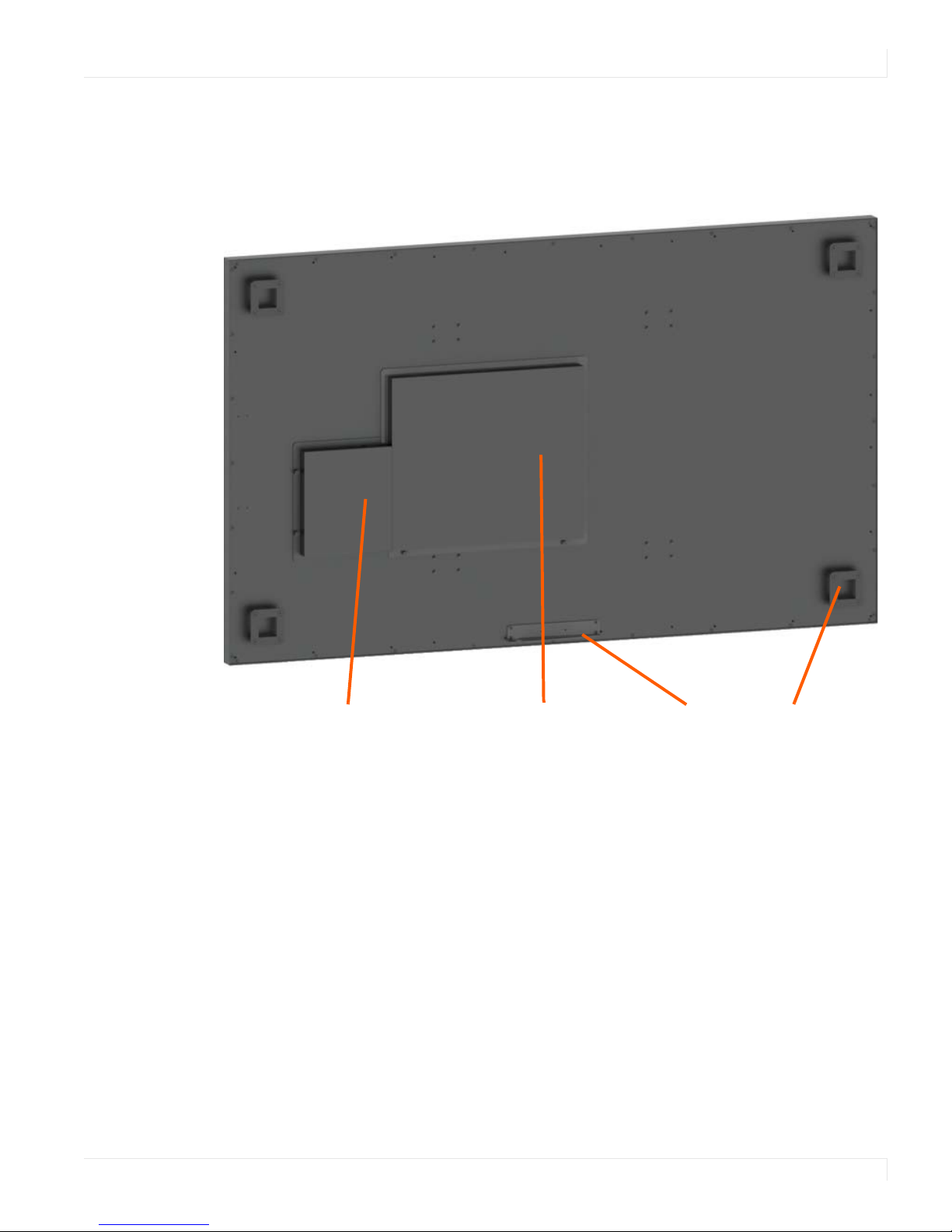
Planar UltraLux Series Features
Control
module/redundant
power supply
Mounting
bracket
Integrated media
player compartment
Kickstand
stop bracket
The Planar UltraLux Series delivers superior 24/7 visual performance with features
enabling easy service and installation.
Planar UltraLux Series Features
Caution: AC power cord needs to be away from the component boxes shown here. This is
due to the very low profile of the space between the back of the LCD and the wall.
Planar UltraLux Series Installation Guide 7
Planar UltraLux Series Features
Profile™ Mounting System with
kick-stand service mode
Wall mount brackets - landscape
$&,1387
,(&&
/$1
3&
56
'%)(0$/(
,55(&(,9(5
9*$,1387
+'0,',*,7$/
,1387
',63/$<3257
',*,7$/,1387
$8;32:(5
287387
6(59,&(&29(5
/2&.6&5(:
86(3+
Leave in “Run” position
to ensure backlight
power is reduced by
50% if a power supply
fails.
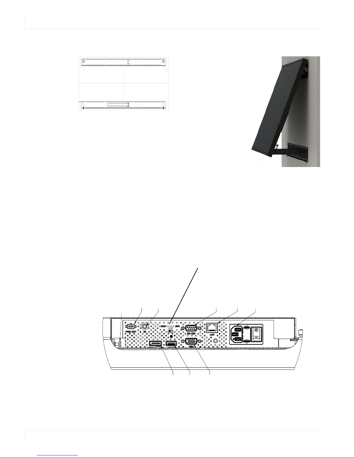
UltraLux Mounting System
electronics. Eliminating the need to completely remove
the display from the wall reduces complexity and service
time by up to 70%.
The Planar Profile™
Mounting System allows
for simplified installation.
The Profile Mounting
System includes two wall
brackets and
incorporates a kick-stand
feature that tilts the
display away from the
wall for easy access to the
Control Module
On the back of the UltraLux display is a replaceable control module that contains the
inputs and outputs shown below. The entire module is designed so that it can be
easily replaced in the field without having to remove the LCD display.
8 Planar UltraLux Series Installation Guide

Redundant Power Supply
A redundant power supply design ensures continuous operation. If one power
supply fails, the remaining power supply will continue to power the display helping
to ensure uninterrupted operation. Each power supply has an output of 24V.
Video Board
This contains HDMI, DisplayPort and VGA inputs. It also contains a LAN board with
Ethernet and RS232 ports.
Power Board
This is used to generate the required voltages needed to run the control module.
Integrated Media Player Storage
Planar UltraLux displays incorporate a 1U media player compartment enabling a
fully-integrated digital signage display system that can power a 5V or 12V media
player up to 3A on each supply.
Planar UltraLux Series Features
LED Technology
With edge-lit LED technology, the Planar UltraLux Series delivers reduced power
consumption and lowered operating costs over the life of the display by up to 60%
compared to CCFL technology.
RS232 and LAN With SNMP Monitoring
Control and status monitoring and integration with enterprise management
solutions.
Planar UltraLux Series Installation Guide 9
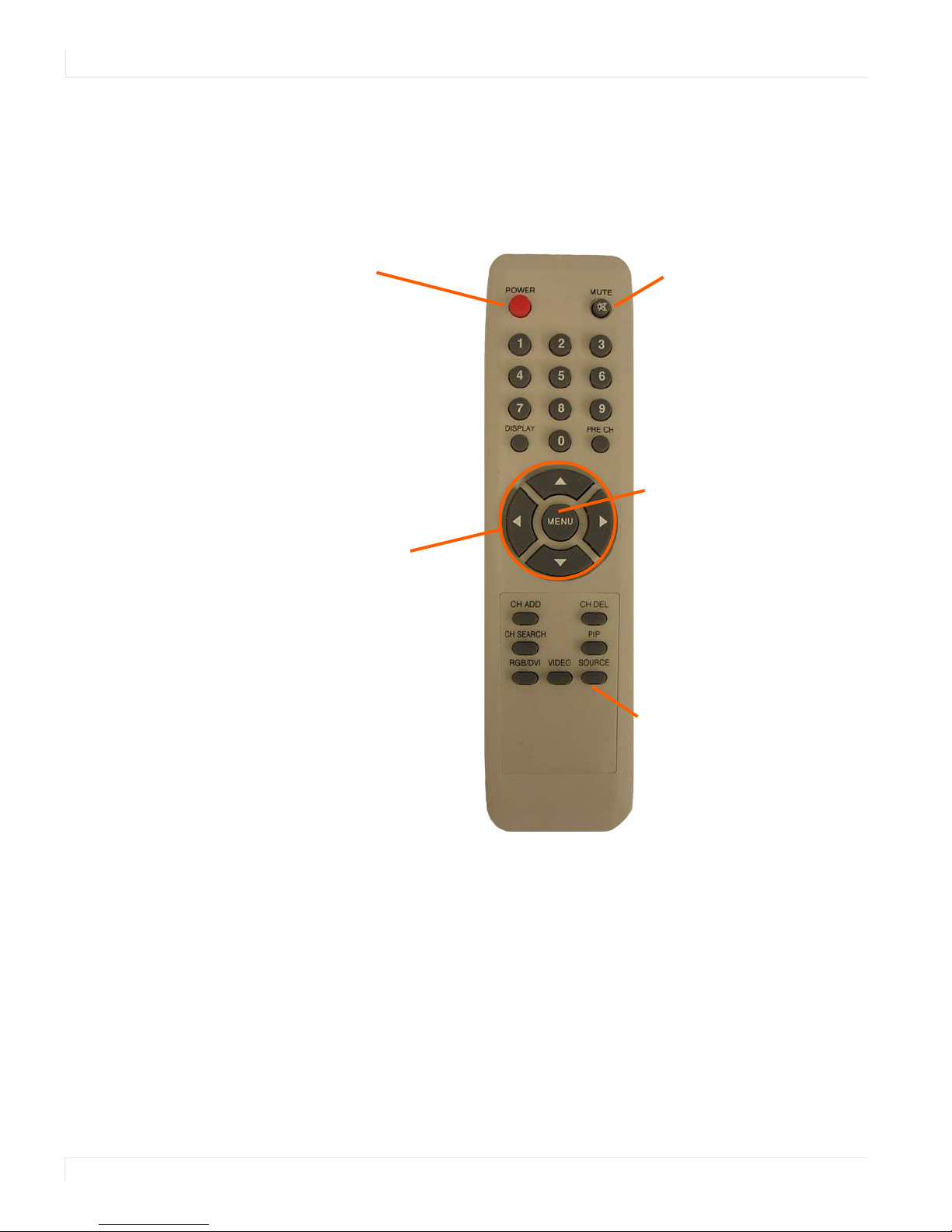
Remote Control
Turns on/off the AC
power to the LCD
module.
Mutes the audio.
Press to access on-screen
menus.
Four arrow keys
move the selector as
shown: up, down,
left or right.
Select this to choose a source.
Also use as the Back button
when navigating through
menus.
Remote Control
All on-screen functions can be accessed using the remote control. Note that only the
buttons highlighted below are applicable to the UltraLux Series panels.
10 Planar UltraLux Series Installation Guide

Safety Information
This display was designed with safety in mind. If you don’t heed the safety warnings
and cautions, you could get hurt. The safety warnings are on stickers in various places
in and on the display.
Important Safety Instructions
1 Read these instructions.
2 Keep these instructions.
3 Heed all warnings.
4 Follow all instructions.
5 Do not use any of the Planar UltraLux Series products near water.
Safety Information
6 Clean the optically bonded protection glass (ERO
TM
) with a 50-50 mix of water and
isopropyl alcohol with cheesecloth.
7 Do not install near any heat sources such as radiators, heat registers, stoves or
other apparatus (including amplifiers) that produce heat.
8 Do not defeat the safety purpose of the polarized or grounding type plug. A
polarized plug has two blades with one wider than the other. A grounding type
plug has two blades and a third grounding prong. The wide blade or the third
prong is provided for your safety. When the provided plug does not fit into your
outlet, consult an electrician for the replacement of the obsolete outlet.
9 Protect the power cord from being walked on or pinched particularly at plugs,
convenience receptacles and the point where they exit from any of the Planar
UltraLux Series products.
10 The AC input is protected by a 5A slow blow fuse located in the AC inlet module.
The fuse is replaceable and the recommended fuse is Schurter part number
0034.3124.
11 Only use the attachments/accessories specified by the manufacturer.
12 Unplug all Planar UltraLux Series products during lightning storms or when
unused for long periods of time.
13 Ensure that the RUN/SVC switch on the control module is in the “Run” position
unless the display is being serviced. This will ensure that if one power supply fails
that the backlights will be reduced by 50% to save power.
Planar UltraLux Series Installation Guide 11

Safety Information
14 You must follow all National Electrical Code regulations. In addition, be aware of
local codes and ordinances when installing your system.
15 Refer all servicing to qualified service personnel. Servicing is required when any
of the Planar UltraLux Series displays have been damaged in any way, such as the
AC power cord or plug is damaged, liquid has been spilled or objects have fallen
into the display, or if the displays have been exposed to rain or moisture, do not
operate normally or have been dropped.
16 Keep the packing material in case the equipment should ever need to be
shipped.
17 Wall mounts must be secure. The wall must be strong enough to hold all displays,
mounts, brackets and cables.
18 Slight pressure on the LCD will cause distortion of the image. Heavier pressure
will cause permanent damage. Planar UltraLux Series configurations should be
mounted in a way that viewers cannot insert small objects in the openings that
will create hazards by contacting bare conductive parts.
12 Planar UltraLux Series Installation Guide
European Union Disposal Information
English
■ Disposal of old Electrical & Electronic Equipment (Applicable throughout
the European Union and other European countries with separate collection
programs)
This symbol found on your product or on its packaging, indicates that
this product should not be treated as household waste when you wish to
dispose of it. Instead, it should be handed over to an applicable collection
point for the recycling of electrical and electronic equipment. By ensuring
this product is disposed of correctly, you will help prevent potential
negative consequences to the environment and human health, which
could otherwise be caused by inappropriate disposal of this product. The
recycling of materials will help to conserve natural resources.
This symbol is only valid in the European Union.
If you wish to discard this product, please contact
your local authorities or dealer and ask for the correct method of disposal.
Español
■ Deshecho de equipos eléctricos y electrónicos (aplicable a la Unión Euro-
pea y a otros países europeos con programas de reciclaje independientes)
La presencia de este símbolo en el propio producto o en su material de
embalaje, indica que no se debe tratar como residuo doméstico cuando
desee deshacerse de él. En su lugar, debe entregarlo en el punto limpio
correspondiente de reciclaje de equipos eléctricos y electrónicos. Asegurándose de que este producto se desecha de forma correcta, ayudará
a evitar posibles consecuencias negativas para la conservación del
medioambiente y la salud humana, consecuencias que podrían darse si
se deshace del producto de forma inadecuada. El reciclado de materiales
ayuda a conservar los recursos naturales.
Este símbolo solamente es válido en la Unión
Europea.
Si desea deshacerse de este producto, póngase
en contacto con las autoridades locales o con su
distribuidor y pida información sobre el método de
disposición adecuado.
Français
■ Mise au rebut des équipements électriques et électroniques usagés
(Valable dans l’ensemble de l’Union Européenne ainsi que dans les pays
européens disposant de programmes distincts de collecte des déchets)
Ce symbole appliqué sur votre produit ou sur son emballage indique
que ce produit ne doit pas être traité comme un déchet ménager lorsque
vous voulez le mettre au rebut. Il doit au contraire être remis à un site
de collecte agréé pour le recyclage des équipements électriques et
électroniques. En veillant à ce que ce produit soit mis au rebut de façon
adéquate, vous contribuerez à prévenir les conséquences potentiellement
négatives sur l’environnement et sur la santé humaine qui risqueraient
de se produire en cas de mise au rebut inappropriée de ce produit. Le
recyclage des matériaux contribuera également à économiser les ressources naturelles.
Ce symbole n’est valable que dans l’Union Européenne.
Si vous souhaitez mettre ce produit au rebut, veuillez
prendre contact avec les autorités locales ou avec votre
revendeur et renseignez-vous sur la méthode de mise
au rebut correcte.
Italiano
■ Smaltimento delle attrezzature elettriche ed elettroniche usate (applicabile
in tutta la Comunità Europea ed altri Paesi Europei che applicano
programmi di raccolta differenziata)
Il simbolo trovato sul prodotto, o sulla sua confezione, indica che il
prodotto non può essere trattato come i domestici quando è il momento
di smaltirlo. Al contrario, deve essere consegnato ad un centro di raccolta
specializzato nel riciclaggio di attrezzature elettriche ed elettroniche. Assicurando che il corretto smaltimento di questo prodotto, si aiuterà a prevenire potenziali conseguenze negative sull’ambiente e sulla salute umana,
che possono essere provocate da uno scorretto smaltimento di questa
attrezzatura. I materiali riciclati aiuteranno a conservare le risorse naturali.
Questo simbolo è valido solo nell’Unione Europea.
Per smaltire questo prodotto, mettersi in contatto con
le autorità locali – o con il rivenditore – e chiedere
informazioni sul corretto metodo di smaltimento.
Deutsch
■ Entsorgung von elektrischen & elektronischen Altgeräten (geltend für die
europäische Gemeinschaft und andere europäische Länder mit separaten
Sammelprogrammen)
Dieses Symbol, zu finden auf Ihrem Produkt oder dessen Verpackung,
macht Sie darauf aufmerksam, dass dieses Produkt bei der Entsorgung
nicht als Hausmüll behandelt werden darf. Statt dessen sollte es an eine
Sammelstelle zum Recycling von elektrischen und elektronischen Altgeräten gegeben werden. Helfen Sie mit, potenziell schädliche Einflüsse
auf Umwelt und Gesundheit, die durch eine unsachgemäße Entsorgung
dieses Produktes entstehen können, zu vermeiden und entsorgen Sie
dieses Produkt ordnungsgemäß. Recycling hilft, natürliche Rohstoffe
einzusparen.
Dieses Symbol ist nur innerhalb der europäischen
Gemeinschaft gültig.
Wenn Sie dieses Produkt entsorgen möchten, wenden
Sie sich bitte an Ihre örtliche Behörde und fragen Sie
nach der ordnungsgemäßen Entsorgungsmethode.
Nederlands
■ Verwijderen van oude elektrische en elektronische apparatuur (toepas-
selijk in de volledige Europese Unie en andere Europese landen met
afzonderlijke programma’s voor afvalverzameling)
Dit symbool dat op het product of zijn verpakking is aangebracht, geeft aan
dat dit product niet mag worden behandeld als huishoudelijk afval als u het
wilt wegwerpen. U moet het afgeven bij een specifiek verzamelpunt voor
de recyclage van elektrische en elektronische apparatuur. Door te garanderen dat u dit product op de correcte manier wegwerpt, helpt u potentiële
negatieve gevolgen voor het milieu en de menselijke gezondheid, die
zouden kunnen worden veroorzaakt door een onrechtmatig wegwerpen
van het product, te voorkomen. De recyclage van materialen helpt het
behoud van natuurlijke bronnen.
Dit symbool is alleen geldig in de Europese Unie.
Als u dit product wenst weg te gooien, dient u contact op
te nemen met uw lokale instanties voor details over de
gepaste methode voor afvalverwijdering.
Português
■ Eliminação de equipamentos eléctricos e electrónicos usados (aplicável
na União Europeia e noutros países europeus com programas próprios de
recolha destes equipamentos)
Este símbolo, colocado no produto ou na respectiva embalagem, indica
que o produto não deve ser tratado como lixo doméstico aquando da sua
eliminação. Em vez disso, deve ser entregue num ponto de recolha de equipamentos eléctricos e electrónicos para posterior reciclagem. Ao garantir
a correcta eliminação deste produto, estará a evitar consequências potencialmente negativas tanto para o ambiente como para a saúde humana. A
reciclagem de materiais ajuda a preservar os recursos naturais.
Este símbolo apenas é válido na União Europeia.
Se quiser eliminar este produto, contacte as entidades locais ou o seu fornecedor para ficar a saber
qual o método de eliminação correcto.
Svenska
■ Avfall av förbrukad elektrisk och elektronisk utrustning (Tillämpbart i
hela Europeiska unionen och andra europeiska länder med separata
samlingsprogram)
Den här symbolen som finns på din product eller på dess förpackning
påvisar att produkten inte ska behandlas som hushållsavfall när du vill
slänga bort den. Istället ska den lämnas över till en lämplig uppsamlingspunkt för återvinning av elektriska och elektroniska utrustningar. Genom att
tillförsäkra att den här produkten återvinns på ett riktigt sätt hjälper du till
med att förhindra möjliga negative konsekvenser för miljön och mänsklig
hälsa. Det kan annars orsakas på grund av olämplig sophantering av den
här produkten. Återvinning av material kommer att hjälpa till att bevara
naturtillgångar.
Den här symbolen är endast giltig inom den
Europeiska unionen.
Om du vill slänga bort den här produkten ska du
kontakta lokala myndigheter eller återförsäljar, och
fråga efter lämplig avfallsmetod.
Polski
■ Usuwanie zużytego sprzętu elektrycznego i elektronicznego (Dotyczy
krajów Unii Europejskiej i innych krajów europejskich z oddzielnymi
programami zbiórki odpadów)
Obecność tego symbolu na produkcie lub na opakowaniu z produktem
oznacza, że tego produktu nie można wyrzucać razem z odpadkami
domowymi. Należy go przekazać do punktu zbiórki w celu poddania
recyklingowi podzespołów elektrycznych i elektronicznych. Usunięcie tego
produktu w prawidłowy sposób, pomoże w zabezpieczeniu przed negatywnym wpływem odpadów na środowisko i zdrowie ludzi, powodowanym
przez niewłaściwe usuwanie produktu. Przetwarzanie materiałów pomaga
w zachowaniu zasobów naturalnych.
Ten symbol obowiązuje wyłącznie w krajach Unii
Europejskiej.
Informacje dotyczące prawidłowej metody usunięcia
tego produktu, można uzyskać u władz lokalnych lub
u dostawcy.
Suomi
■ Vanhojen sähkö- ja elektroniikkalaitteiden hävittäminen (Soveltuva kaik-
kialla Euroopan unionin alueella, sekä muissa Euroopan maissa, joilla on
erilliset keräysohjelmat)
Jos tuotteessa tai sen pakkauksessa on tämä symboli, sitä ei pidä
hävitettäessä käsitellä tavallisena kotitalousjätteenä, vaan se kuuluu toimittaa sähkö- ja elektroniikkalaitteiden kierrätyspisteeseen. Varmistamalla,
että tämä tuote hävitetään asiaankuuluvalla tavalla autat estämään mahdollisia ympäristölle ja ihmisille koituvia negatiivisia seuraamuksia, joita
sen vääränlainen hävittäminen voi aiheuttaa. Materiaalien kierrättäminen
auttaa säilyttämään luonnonvaroja.
Tämä symboli on voimassa ainoastaan Euroopan
unionin alueella.
Jos haluat hävittää tämän tuotteen, ota yhteyttä
paikallisiin viranomaisiin tai jälleenmyyjään ja tiedustele
asiaankuuluvia hävittämistoimenpiteitä.
WasteElectricalandElectronicEquipment(WEEE)Directive
IntheEuropeanUnion,thislabelindicatesthatthisproduct
shouldnotbedisposedofwithhouseholdwaste.Itshould
bedepositedatanappropriatefacilitytoenablerecovery
andrecycling.EEEcomplieswithDirective‘Regulationon
theRestrictionoftheUseofCertain
HazardousSubstances
inElectricalandElectronicEquipment’
WasteElectricalandElectronicEquipment
(WEEE)DirectiveIntheEuropeanUnion,this
labelindicatesthatthisproductshouldnotbe
disposedofwithhouseholdwaste.Itshouldbe
depositedatanappropriatefacilitytoenable
recoveryandrecycling.EEEcomplieswith
Directive‘RegulationontheRestrictionofthe
UseofCertain
HazardousSubstancesin
ElectricalandElectronicEquipment’
WasteElectricalandElectronicEquipment(WEEE)
YönergeleriAvrupaBirliği'ndebuetiket,ürününev
elektroniğialetleriatıklarıileimhaedilemeyeceğinigösterir.
Kurtarmakvegeridönüşümünüsağlamakiçinuygun
şartlardasaklanmasıgerekir.EEEYönetmeliğineUygundur
VeElektronikEşyalardaBaziZararliMaddelerinKullaniminin
Sinirlandirilmasina
DairYönetmelik.
Waste Electrical and Electronic Equipment
(WEEE) Yönergeleri Avrupa Birliği'nde bu etiket,
ürünün ev elektroniği aletleri atıkları ile imha
edilemeyeceğini gösterir. Kurtarmak ve geri
dönüşümünü sağlamak için uygun şartlarda
saklanması gerekir. EEE Yönetmeliğine
Uygundur Ve Elektronik Eşyalarda Bazi Zararli
Maddelerin Kullaniminin Sinirlandirilmasina
Dair Yönetmelik.
Safety Information
Planar UltraLux Series Installation Guide 13

Recommended Usage
Recommended Usage
The UltraLux series uses commercial grade LCD panels, and is designed for 24/7
operation. With certain static images and extreme conditions, a slight amount of
temporary image retention may occur. To minimize this possibility, it is
recommended that either static images be changed occasionally (for example to a
different screen layout, or a black screen), or that a periodic display shutdown be
programmed using RS232 commands or the UltraLux Remote Monitoring software.
In order to get the most out of your LCD modules, use the following recommended
guidelines to optimize the display.
Burn-In Versus Temporary Image Retention
Burn-in causes the screen to retain an image essentially forever, with little or no way
to correct the problem. Under normal use, an LCD module will not experience burnin, as plasma displays do, nor will it retain images in any way.
Normal use of an LCD module is defined as displaying continuously changing video
patterns or images. However, LCD modules can experience temporary image
retention when recommended usage guidelines are not followed.
What is Temporary Image Retention?
Temporary image retention (TIR) can occur when a static image is displayed
continuously for extended periods of time. An electrical charge differential may build
up between the electrodes of the liquid crystal, which causes a negative-color video
image (color-inverted and brightness-inverted version of the previous image) to be
retained when a new image is displayed. This behavior is true for any LCD device
from any LCD manufacturer.
TIR is not covered under warranty. See standard warranty terms and conditions for
details. Here are some guidelines to help you avoid TIR:
• Use the LCD module to show a screen saver, moving images or still pictures that
change regularly. When using high-contrast images, reposition the images
frequently.
• Turn off the UltraLux Series when it is not in use. There are a couple of ways to
do this automatically. See "Powering On/Off Displays" on page 17 more
information. To use serial commands, see "RS232 Communication" on page 34.
14 Planar UltraLux Series Installation Guide

Normal Use Thermal Guidelines
Normal use of the LCD module and power supply module are defined as operating in
the open air to prevent heat buildup, and without direct or indirect heat sources such
as lighting fixtures, heating ducts, or direct sunlight that can cause the modules to
experience high operating temperatures. For all modules, do not block fans or
ventilation openings. If the LCD module will be installed in a recessed area with an
LCD surround or enclosure, ensure adequate openings are applied for proper air flow
and ventilation.
At 2000 meters or below, the maximum ambient operating temperature for the LCD
module cannot be above 104º F (40º C) and 35º C for 80” portrait, nor below the
minimum ambient operating temperature of (32º F) 0º C. If one of these conditions
exists, it is up to the installer to ensure that module placement is changed, thermal
shielding is provided and/or additional ventilation is provided to keep the display
within its nominal operating parameters.
Cooling Requirements
For optimal performance, active cooling by the installer should be planned for when
the ambient temperature anywhere in the display is predicted to be above the
specified ambient temperature for the display.
Recommended Usage
Using the Display in Flat Orientation
The UltraLux is not recommended for use in flat orientation for tabletop, floor, or
ceiling installations. LCD panels of this size are at risk of panel deflection, which can
cause cosmetic sagging, brightness uniformity issues, and a shortened life span.
Planar UltraLux Series Installation Guide 15

Installing the Planar
UltraLux Series
This section explains how to install a Planar UltraLux display. We suggest that you
read this entire section before you attempt an installation.
Before You Begin
Make sure you have all the items in the following lists before you begin unpacking
and installing your Planar UltraLux Series.
Tools/Equipment List
Depending on your installation, you may need one or more of the following items.
Note that depending on the size of the display, this list may be different.
• #1 and # 2 Phillips screwdriver
• Drill and bits
• Nut drivers
•Pencil
• Digital/laser level
• Ladders/lift
• Back brace
• Stud finder (if hanging LCD modules on a wall)
Other Things You May Need
• A 50-50 mix of water and isopropyl alcohol, as well as cheesecloth to clean the
displays.
• At least
Plan Your Installation
You should have a detailed plan of how the UltraLux is to be installed. The plan
should include calculations for the following:
• Floor/wall load. Make sure the floor/wall is strong enough to support the
weight of the UltraLux Series.
• AC receptacle in safe zone where boxes are to be stored.
two capable people to lift LCDs into place.
16 Planar UltraLux Series Installation Guide

Powering On/Off Displays
There are several ways to turn the UltraLux Series on or off:
• Use the on/off switch on the AC power inlet
• Use the power button on the remote control
• Use the RS232 commands
• Use the UltraLux Remote Monitoring embedded software via Ethernet
Powering On/Off Displays
Planar UltraLux Series Installation Guide 17
Unpacking and Checking Accessories
Unpacking and Checking Accessories
The UltraLux includes the LCD and an accessory kit. A wall mount kit can be
purchased separately.
Note: Screws should be no less than 1/4” in diameter. You will need a minimum of eight
screws for the top mounting bracket and a minimum of four for the bottom kickstand
bracket. Additional screws may be needed depending on your installation.
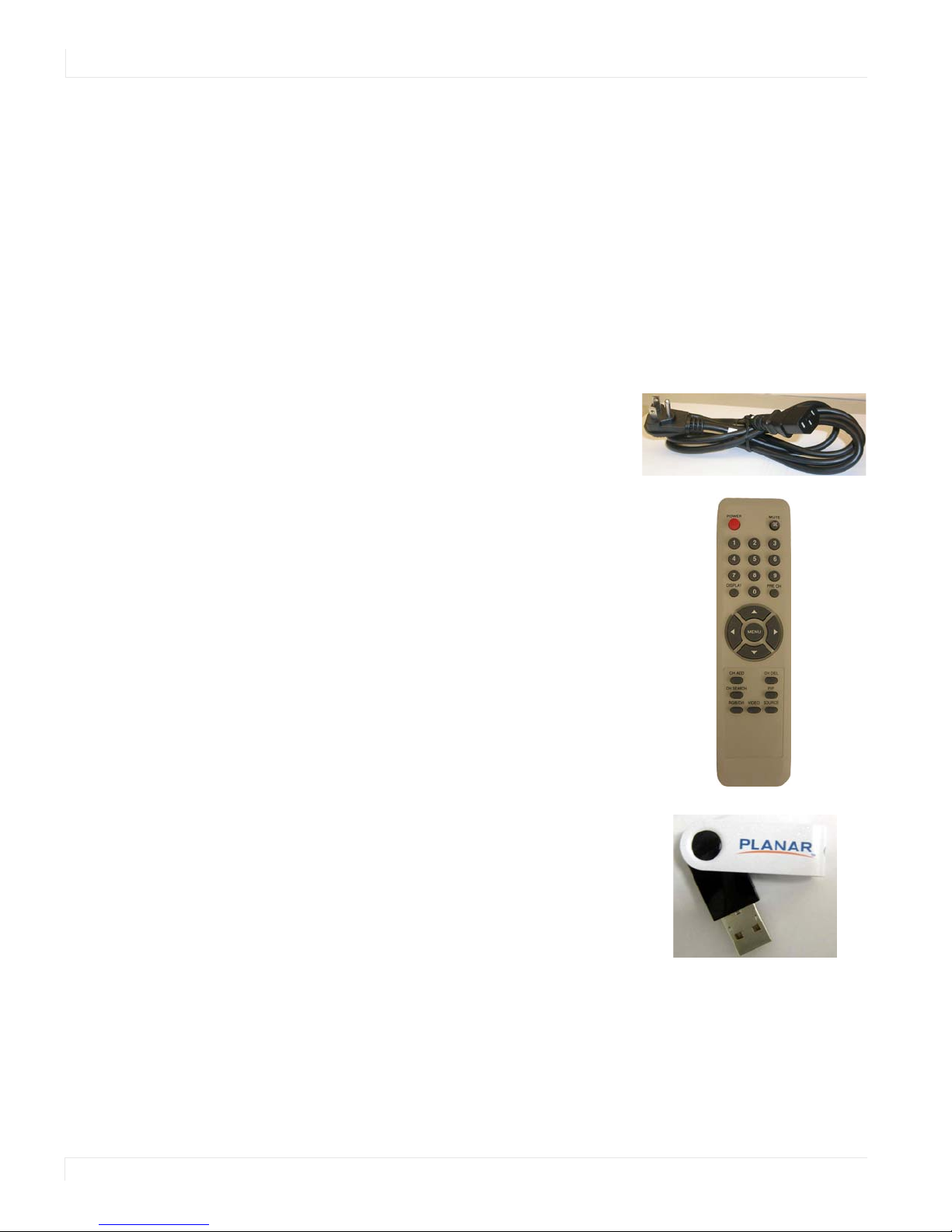
Accessory Kit
Part Description Picture
AC power cord 90 degree low profile power cord.
Remote control Used to turn on/off displays, as well as
to navigate through on-screen menus.
Note: Batteries are included and
installed.
USB drive Contains the Planar UltraLux Series
Installation Guide.
18 Planar UltraLux Series Installation Guide

Part Description Picture
IR extender cable Used to receive signals from the
remote
Optional Planar-Supplied Accessories
The following optional items are available to order as part of your installation:
• Planar ContentSmartTM Media Player
•Profile
TM
Wall Mount
Unpacking and Checking Accessories
Planar UltraLux Series Installation Guide 19

Wall Mounting LCD
Using Planar Profile
Mount
Before installation, keep the following points in mind:
• These displays are heavy. Make sure that you have adequate studs to support
the weight of each display if installing on a wall.
• The UltraLux must be installed on a flat surface.
• Use supplied UltraLux mounting template for top and bottom bracket
installation.
• The wall mounts for a landscape and portrait installation look different.
However, the process to install them is exactly the same.
• The Planar Profile mount is not designed for tabletop installations.
20 Planar UltraLux Series Installation Guide

Installing an UltraLux Display on a Wall
Caution: For whatever structure is used to mount the display, be sure that it is sufficiently
engineered to handle the weight of the display. Also be sure to purchase the correct
hardware needed to support the display mounted to that structure.
1
Find the center point of the display on the wall where you intend to install it.
Installing an UltraLux Display on a Wall
2 Draw a short (about 1”) horizontal line and then a vertical line to match the edge
of the display.
Planar UltraLux Series Installation Guide 21
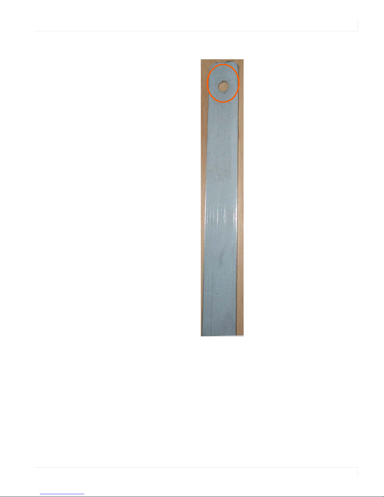
Installing an UltraLux Display on a Wall
Center notch alignment
3 Use the provided template to determine the center points of the wall mounts.
The “V” notches are labeled “L” for a landscape display or “P” for a portrait display.
Use the appropriate “V” notch to align with the horizontal line drawn in the
previous step.
22 Planar UltraLux Series Installation Guide
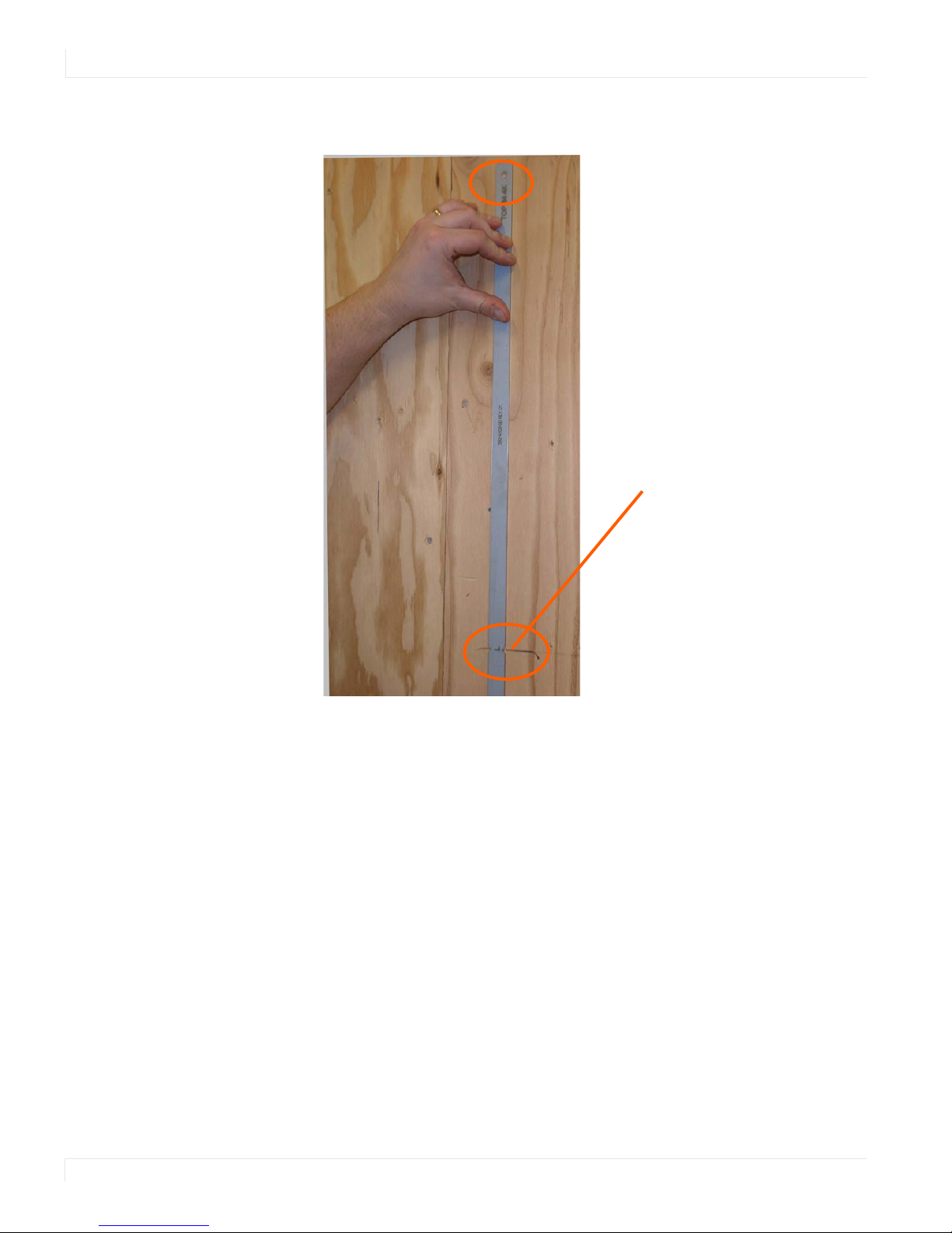
Installing an UltraLux Display on a Wall
4 In the hole marked “Top” on the template, mark the center of the hole on the wall.
Note: If you are installing a landscape display and the template is too long, you can break the
template at the notch labeled “P.”
5
Let the template hang vertically so it is plumb, as the bottom hole in the template
determines where the bottom mount will be installed.
6 Screw the appropriate hardware into the bottom hole of the template that
corresponds with your display orientation.
7 Remove each screw and the template.
Planar UltraLux Series Installation Guide 23
Installing an UltraLux Display on a Wall
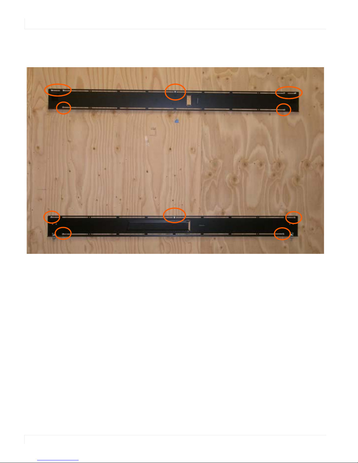
8 Line up the middle hole of the top wall mount with the screw hole drilled from
the template.
Note: This picture shows mounts for a landscape installation.
Tighten the screw into the mount.
9
10 Use a level to make sure the mount is level.
11 Then install additional screws as needed.
Note: Screws installed near the mount hooks provide the best support.
Install the center screw in the bottom mount and repeat steps 10-11 for any
12
additional screws that you want to install. Note that there are open mount
channels on the brackets. So you can install the screws wherever necessary along
those channels.
24 Planar UltraLux Series Installation Guide
Installing an UltraLux Display on a Wall
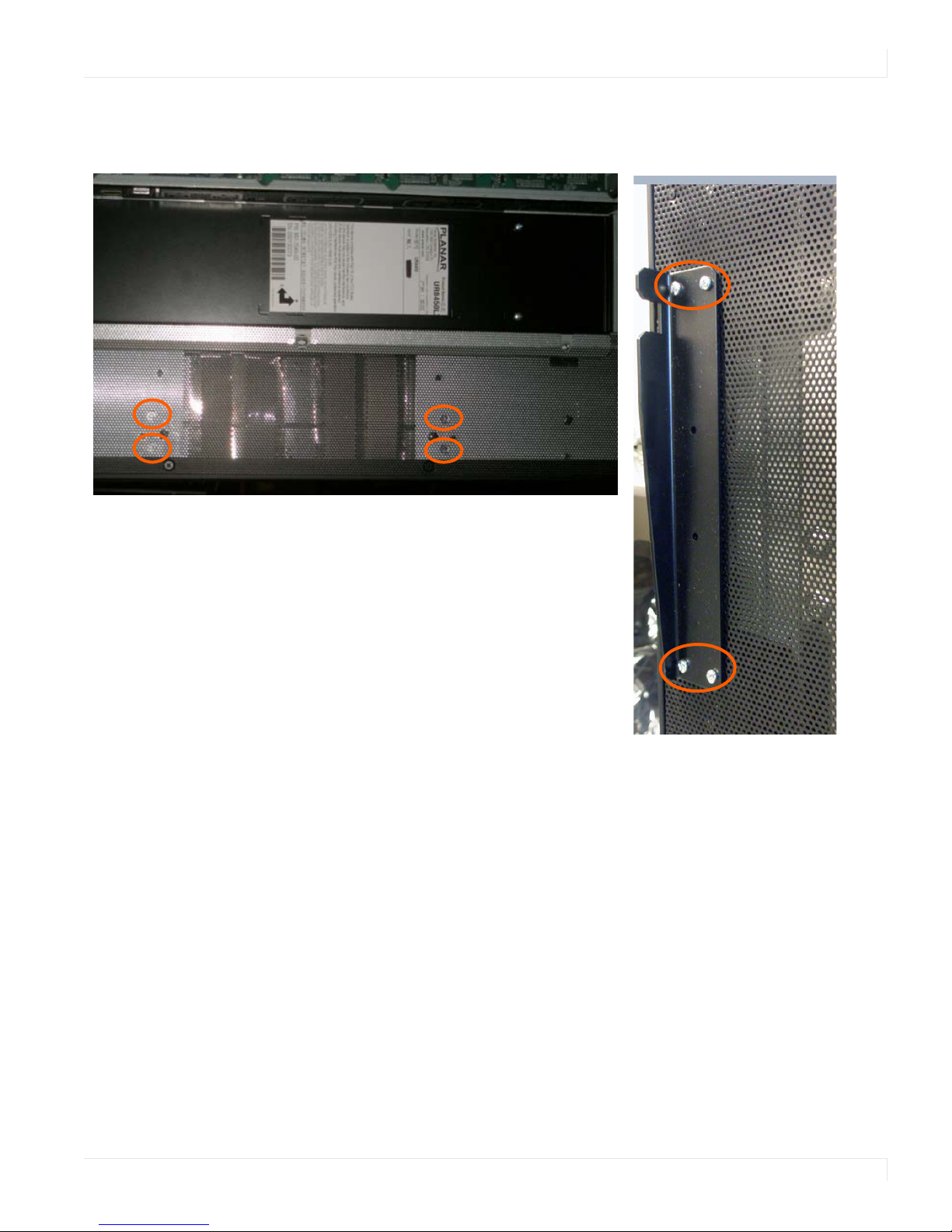
Landscape holes for kickstand bracket installation
Portrait kickstand installed on display
13 Install the kickstand bracket to the back of the display using four M4 x 8 panhead
screws.
Planar UltraLux Series Installation Guide 25
Installing an UltraLux Display on a Wall
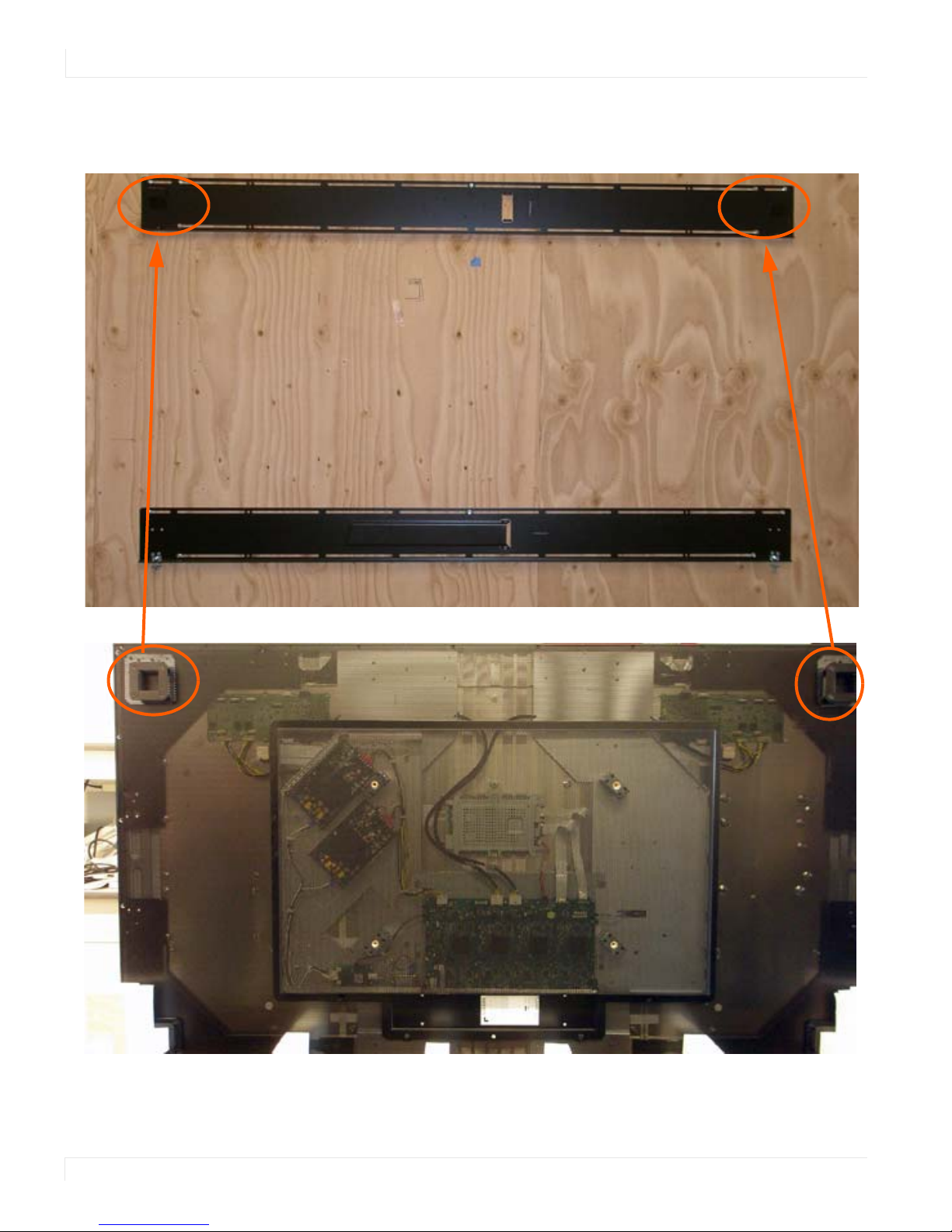
14 Using three strong people, carefully hang the back of the display onto the top
wall mount bracket using the square brackets on the back of the display.
Caution: Be sure these are securely hung, as the top of the wall mount will hold most of the
weight of the display.
26 Planar UltraLux Series Installation Guide
Installing an UltraLux Display on a Wall
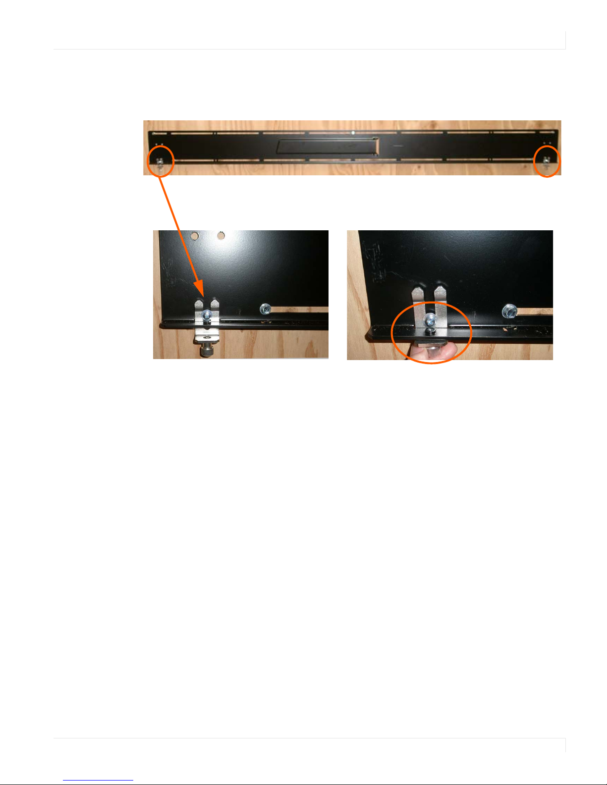
15 On the bottom wall mount, there is locking hardware in the lower corners of the
mount. Push the hardware up and finger tighten the captive screws on the
bottom to secure the display to the wall.
Planar UltraLux Series Installation Guide 27
 Loading...