

Page 1

Dome® RX/PCI
Display Controller
INSTALLATION GUIDE
Windows XP
Windows 2000
Windows NT 4.0
Solaris 2.5.1 or later
www.planar.com
Page 2

Copyright © DOME® imaging systems, inc., 2002. All rights reserved.
This document contains proprietary information of DOME imaging systems,
inc. It is DOME’s exclusive property. It may not be reproduced or transmitted, in whole or in part, without a written agreement from DOME. No patent
or other license is granted to this information.
The software, if any, described in this document is furnished under a license
agreement. The software may not be used or copied except as provided in
the license agreement.
DOME imaging systems, inc. provides this publication as is without warranty of any kind, either express or implied, including but not limited to the
implied warranties of merchantability or fitness for a particular purpose.
DOME may revise this document from time to time without notice. Some
states or jurisdictions do not allow disclaimer of express or implied warranties in certain transactions; therefore, this statement may not apply to you.
Information in this document about products not manufactured by DOME is
provided without warranty or representation of any kind, and DOME will
not be liable for any damages resulting from the use of such information.
DOME imaging systems, inc.
400 Fifth Avenue
Waltham, MA 02451-8738
(781) 895-1155 phone
(781) 895-1133 fax
Internet address for documentation:
Internet address for product information:
Internet address for sales information:
Internet address for technical support:
World Wide Web site:
www.dome.com
techpubs@dome.com
info@dome.com
sales@dome.com
support@dome.com
Part No. 40-RXPCI-02
Product Nos. 55-R4PCI2, 55-R5PCI2
May 2002
DOME and the DOME logo are registered trademarks, and Calibration TQA,
R4/PCI, and R5/PCI are trademarks of DOME imaging systems, inc.
ActiveX, DirectDraw, Microsoft, MS-DOS, Windows, Windows NT,
Windows XP, and Windows 2000 are trademarks of Microsoft Corporation.
Intel is a trademark of Intel Corporation. OpenWindows, Solaris, Sun, and
Ultra are trademarks of Sun Microsystems, Inc. All SPARC trademarks are
trademarks of SPARC International, Inc. SPARCstation is licensed exclusively to Sun Microsystems, Inc. Products bearing SPARC trademarks are
based on an architecture developed by Sun Microsystems, Inc. UNIX is a
trademark of The Open Group. VGA is a trademark of International Business
Machines Corporation.
Page 3

FCC Compliance Statement
This equipment generates, uses, and can radiate radio frequency energy and,
if not installed and used in accordance with the instruction manual, may
cause interference to radio communications. It has been tested and found to
comply with the limits of a Class A computing device pursuant to Subpart J
of Part 15 of FCC Rules, which are designed to provide reasonable protection
against interference when operated in a commercial environment. Operation
of this equipment in a residential area is likely to cause interference, in which
case the user will be required at his or her own expense to take whatever
measures may be required to correct the interference.
If the equipment does cause interference to radio or television reception,
which can be determined by turning the equipment on and off, one or more
of the following measures may reduce or eliminate the problem.
• Move the equipment and the receiver to different branches of your
AC electrical system.
iii
• Move the equipment away from the receiver with which it is
interfering.
• Reposition the equipment or receiver. Reposition the receiver’s antenna.
• Be sure that the equipment is plugged into a grounded outlet and that the
grounding has not been defeated with a cheater plug.
If none of the measures resolves your interference problems, write to the
U.S. Government Printing Office, Washington, DC, 20402, for the booklet
Interference to Home Electronic Entertainment Equipment Handbook
Number 004-000-000498-1.
This equipment is a Class A digital apparatus that complies with the
Radio Interference Regulations CRC C.1374.
In addition, this equipment has been tested and found to comply with the
limits for a Class B digital device, pursuant to Part 15 of the FCC rules. These
limits are designed to provide reasonable protection against harmful interference in residential installations.
, Stock
Page 4

iv
EU Declaration of Conformity
The R4/PCI and R5/PCI display controllers (models 55-R4PCI2 and
55-R5PCI2) meet the essential health and safety requirements, are in conformity with and the CE marking has been applied according to the relevant
EU Directives listed below using the relevant section of the following EU
standards and other normative documents;
EU EMC Directive 89/336/EEC
EU Electromagnetic Compatibility Directive
EN 60601-1-2 (Draft 1 March 18, 1996) Medical
Electrical Equipment
EN 55011 (Class B) Limits and methods of measurements
IEC 1000-3-2 Harmonic emissions
IEC 1000-3-3 Voltage fluctuations/flicker emissions
IEC 1000-4-2 Electrostatic discharge requirements for
IEC 1000-4-3 Radiated electromagnetic field requirements
IEC 1000-4-4 Electrically fast transients for industrial
IEC 1000-4-5 Surge requirements
IEC 1000-4-11 Voltage variations/dips/interrupts
Part 1. General requirements for safety
Section 1.2. Collateral standard electromagnetic compatibility requirements
for radio interference characteristics of
industrial, scientific, and medical equipment
industrial process measurement and control
equipment
for industrial process measurement and
control equipment
process measurement and control equipment
IEC 1000-4-6 Conducted immunity
IEC 1000-4-8 Magnetic field immunity
Name and Title of Authorized Signatory: Date:
Marlin Cobb
Vice President of Product Development
DOME imaging systems, inc.
Page 5

Contents
v
About This Guide
vii
1 System Requirements 1
Platform Requirements 1
Installation process 2
2 Installing the Board and Display 3
Unpacking the Board 3
Setting DIP Switches on the Board 4
Enabling and disabling VGA mode 4
Supporting VGA for PCs 5
Disabling VGA mode for Sun workstations 7
Installing the Board 8
Installing multiple boards 10
Connecting the Displays 11
3 Windows 2000 Driver 13
Installing the Windows 2000 Driver 13
Configuring Display Settings 19
Determining screen assignments 19
Using the DOME tab to change display properties 20
Uninstalling DOME Devices on Windows 2000 23
Uninstalling a dual-headed DOME device 25
Using Calibration TQA on Windows 2000 27
4 Windows NT 4.0 Driver 29
Installing the Windows NT 4.0 Driver 29
Configuring Display Settings 32
Using the DOME tab to change display properties 35
Setting palette options 38
Setting monitor preferences 38
Setting the driver options 38
Additional Display Settings 40
DOME large fonts 40
DOME DlgFix software 43
DOME DPMS Screen Saver for Windows NT 44
Page 6

vi
| Contents
5 Solaris Driver 49
Installing the Solaris Driver 49
Configuring Display Settings 52
Using the default display mode 52
Overriding the default display mode 52
Modifying the OWconfig file 54
Using Visual Classes 56
Configuring the Windowing Environment 60
Using the DPMS Screen Saver with CDE 62
Changing the Console 65
Appendix A: Resolutions and Refresh Rates 67
Resolutions and Refresh Rates for PCs 67
Customizing sync parameters for Windows NT 68
Customizing sync parameters for Windows 2000 or XP 69
Resolutions and Refresh Rates for Sun PCI Workstations 73
Setting switch S1 on Sun PCI workstations 74
Appendix B: Palette Options for Windows Systems 75
Appendix C: Troubleshooting for Windows 2000 81
Windows 2000 or XP Troubleshooting 81
Uninstalling the sister device 81
Uninstalling a single-headed board 82
Unsigned driver load error 82
Impaired screen resolution 83
Index 85
Page 7

About This Guide
Read this section for an overview of how to use this guide before
you unpack the DOME® RX/PCI™ display controller (board).
vii
The term
• R4/PCI™ board
• R5/PCI™ board
Purpose
This guide explains how to install an RX/PCI board in
these computers:
•PC
• Sun™ PCI workstation
It also describes how to install and use the DOME drivers for
these operating systems:
• Microsoft® Windows® XP
• Microsoft Windows 2000
• Microsoft Windows NT® 4.0
RX/PCI board
stands for one of the following:
• Sun Solaris™ 2.5.1 or later
Audience
This guide serves users who are installing an RX/PCI board and
software in a computer. You should be familiar with installing
and configuring hardware and software.
Page 8

viii
| About This Guide
Conventions
This guide uses the conventions listed in this table.
This convention... Indicates...
Monospaced type
Italic type
Bold type
File > Open
<Key> Key name, such as
Computer code or directory; backslash (\)
indicates continuation of the previous line of
UNIX® code.
New or technical term, book title, or variable
such as
Menu selection:
Select the
A note of important information regarding
a particular topic or procedure.
A caution that can prevent potential damage
to hardware or software.
A warning that can prevent injury to you,
such as electric shock.
x.
File
menu, then
<Enter>.
Open
.
A helpful tip or an alternative method of
performing a procedure.
Page 9

What’s in this guide
This guide is organized into these chapters.
This chapter… Describes…
About This Guide |
ix
Chapter 1
System Requirements
Chapter 2
Installing the Board and
Display
Chapter 3
Windows 2000 Driver
Chapter 4
Windows NT 4.0 Driver
Chapter 5
Solaris Driver
Appendix A
Resolutions and Refresh
Rates
System requirements and an overview
of the installation process
Instructions for installing the RX/PCI
board in a PC or a Sun PCI workstation
and attaching a display
Instructions for installing and
configuring the RX/PCI driver for a
Windows XP or 2000 system
Instructions for installing and
configuring the RX/PCI driver for a
Windows NT 4.0 system
Instructions for installing and
configuring the RX/PCI driver for a
Solaris 2.5.1 or later system
Resolutions and refresh rates
supported by the RX/PCI board in
PCs and Sun PCI workstations
Appendix B
Palette Options for
Windows Systems
Appendix C
Troubleshooting for
Windows 2000
Explanations of palette options
available in Windows XP, Windows
2000, and Windows NT systems
Solutions for problems with displays on
a Windows 2000 or XP system
Page 10

x
| About This Guide
Related documentation
Refer to these books for more information:
• PCI Products Developer’s Guide
• Microsoft documentation
• Sun documentation
Page 11

System Requirements
Before you install the RX/PCI board, read this section for
system requirements and an overview of the installation process.
Platform Requirements
You can install the RX/PCI board in a PC or a Sun PCI workstation. This table lists the platform-specific requirements for
system specifications, operating system, and DOME driver.
Requirement PC Sun PCI Workstation
System specs • PCI slot per board
• 2 MB hard disk space
• 16 MB RAM
• 8 MB RAM per screen
• CD-ROM drive
Operating
system
DOME driver • Windows 2000 driver
• Windows XP
• Windows 2000
• Windows NT 4.0
for RX/PCI board (also
used by Windows XP)
• Windows NT 4.0 driver
for RX/PCI board
• PCI slot per board
• 1.2 MB hard disk
space for driver and
DDX installation
• CD-ROM drive
Solaris 2.5.1 or later
Solaris driver for
RX/PCI board
1
Page 12

2
| R5/PCI Installation Guide
Each platform requires a compatible display that supports your
desired display resolution.
Multiple displays for PCs must have the same resolution.
Installation process
Follow these steps to install the RX/PCI board and driver on
a PC or a Sun PCI workstation:
1
Set DIP switches on the board.
2
Install the board.
3
Connect the display(s) to the board.
4
Install the driver.
Page 13

Installing the Board and Display
This chapter explains how to unpack the board, enable or disable
VGA mode, install the board, and connect the displays.
Unpacking the Board
Remove the RX/PCI board slowly from its package and staticshielding bag to protect it against electrostatic discharge.
Static electricity can damage the board. When touching the
board or parts of the motherboard, be sure to take these
precautions:
• Wear an antistatic wrist strap.
• Always keep one hand touching a bare metal surface to
provide grounding.
• If you can’t perform a step with just one hand, use both and
return one hand occasionally to the metal surface.
3
Page 14
4
| Installing the Board and Display
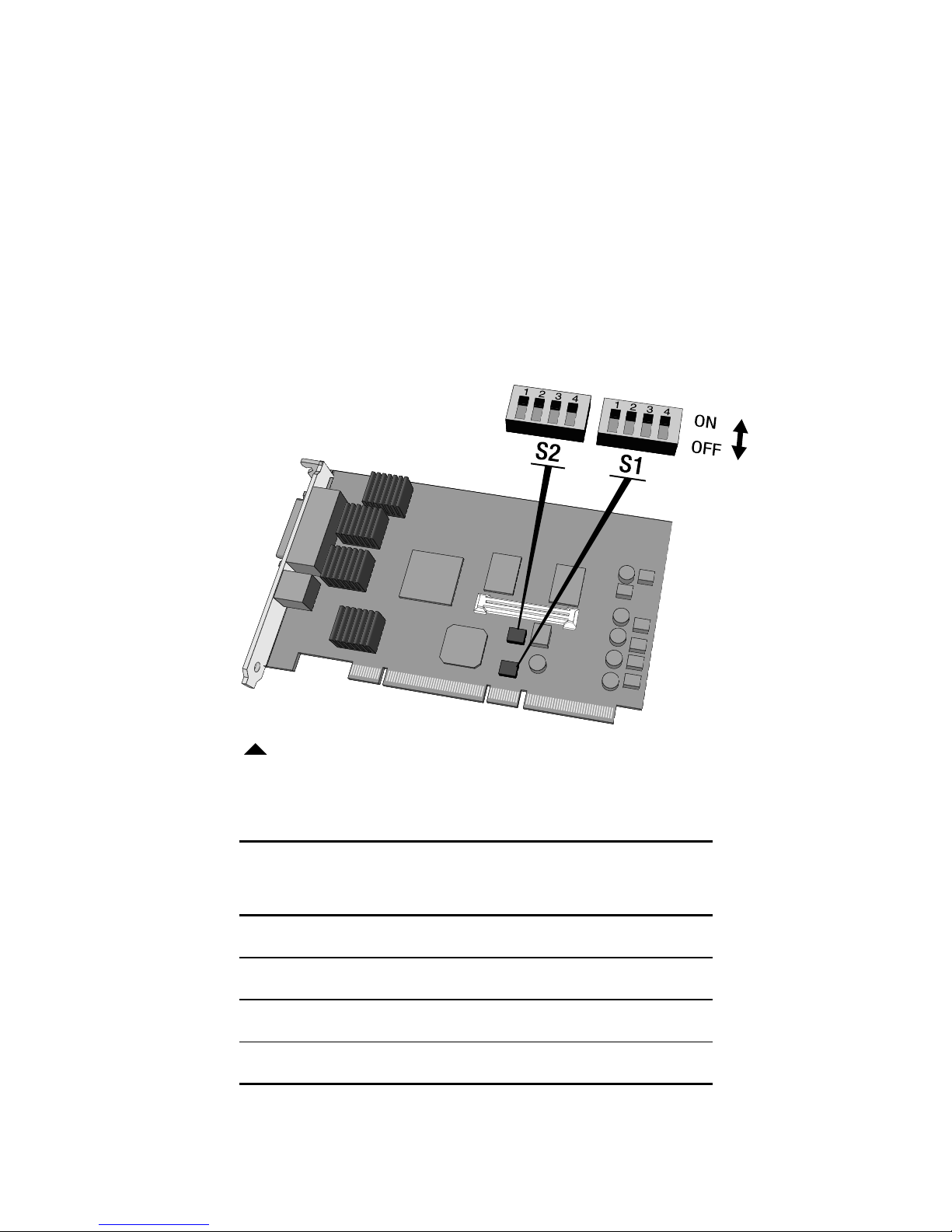
Setting DIP Switches on the Board
Use the DIP switches to enable or disable VGA mode.
Enabling and disabling VGA mode
Set the DIP switches to enable or disable VGA mode. See page 6
for instructions on setting the switches. Here, all switches are in
the ON position for illustrative purposes.
DIP switches on the RX/PCI board
This table shows the setting options for switch S2.
Switch S2
DIP Switch On Off
1 VGA enabled
2 EPROM enabled EPROM disabled
3 Reserved Reserved
4 Reserved Reserved
a. Default setting.
a
VGA disabled
a
a
a
Page 15
The default settings for switch S1, located below switch S2,
are all OFF.
Supporting VGA for PCs
Determine which board will support VGA display:
• The RX/PCI board
• Another VGA board
To install more than one RX/PCI board, see “Installing
multiple boards” on page 10.
Disable VGA mode if the RX/PCI board is used with an existing
VGA board or with multiple RX/PCI boards. Enable VGA if the
RX/PCI board’s VGA port is used.
Setting DIP Switches on the Board |
5
To use the RX/PCI board as the VGA console
1
Remove the existing VGA board from your computer.
2
Enable VGA mode on the RX/PCI board by following the
instructions under “To enable VGA mode” on page 6.
3
Install the RX/PCI board by following the instructions
on page 8.
To support VGA with another board
You must disable VGA mode on the RX/PCI board.
See “To disable VGA mode” on page 6.
When you install the RX/PCI board in a computer with an
existing VGA board, only one board can support the Windows
operating system. You can run Windows on either board, but
you cannot run Windows on both boards simultaneously.
Page 16

6
| Installing the Board and Display
To enable VGA mode
Slide the DIP switches on switch S2 into the positions
indicated in this table.
DIP Switch Setting
1ON
2 OFF
3 OFF
4 OFF
To disable VGA mode
Slide the DIP switches on switch S2 into the positions indicated
in this table.
DIP Switch Setting
1 OFF
2 OFF
3 OFF
4 OFF
Page 17

Setting DIP Switches on the Board |
Disabling VGA mode for Sun workstations
The RX/PCI board cannot operate as a VGA board in a
Sun PCI workstation, so you must disable VGA on the
RX/PCI boards.
Set switch S2 as follows.
DIP Switch Setting
1 OFF
2ON
3 OFF
4 OFF
7
Sun PCI:
If you change the settings for switch S1, the
new settings override the default display mode. See
“Configuring Display Settings” on page 52 for more
information.
Page 18
8
| Installing the Board and Display
Installing the Board
Install all RX/PCI boards before you install the driver.
Follow the safety precautions described on page 3 before you
proceed with board installation.
Turn the computer off, but leave it plugged into a grounded
power outlet so that the power cord serves as a ground for the
computer. If you leave the computer turned on, you might
suffer electric shock or cause damage to both the computer
components and the RX/PCI board.
Static electricity can damage the board. Wear an antistatic wrist
strap or touch one hand to a bare metal surface on the power
supply to discharge static electricity.
To install the board
1
Remove the blank bracket or backplate from the back of
any available PCI slot.
2
Insert the RX/PCI board firmly into the slot. Align the board
connector pins with the slot. Press down until the board is
firmly seated.
3
Secure the mounting bracket with the bracket or
backplate screw.
Page 19
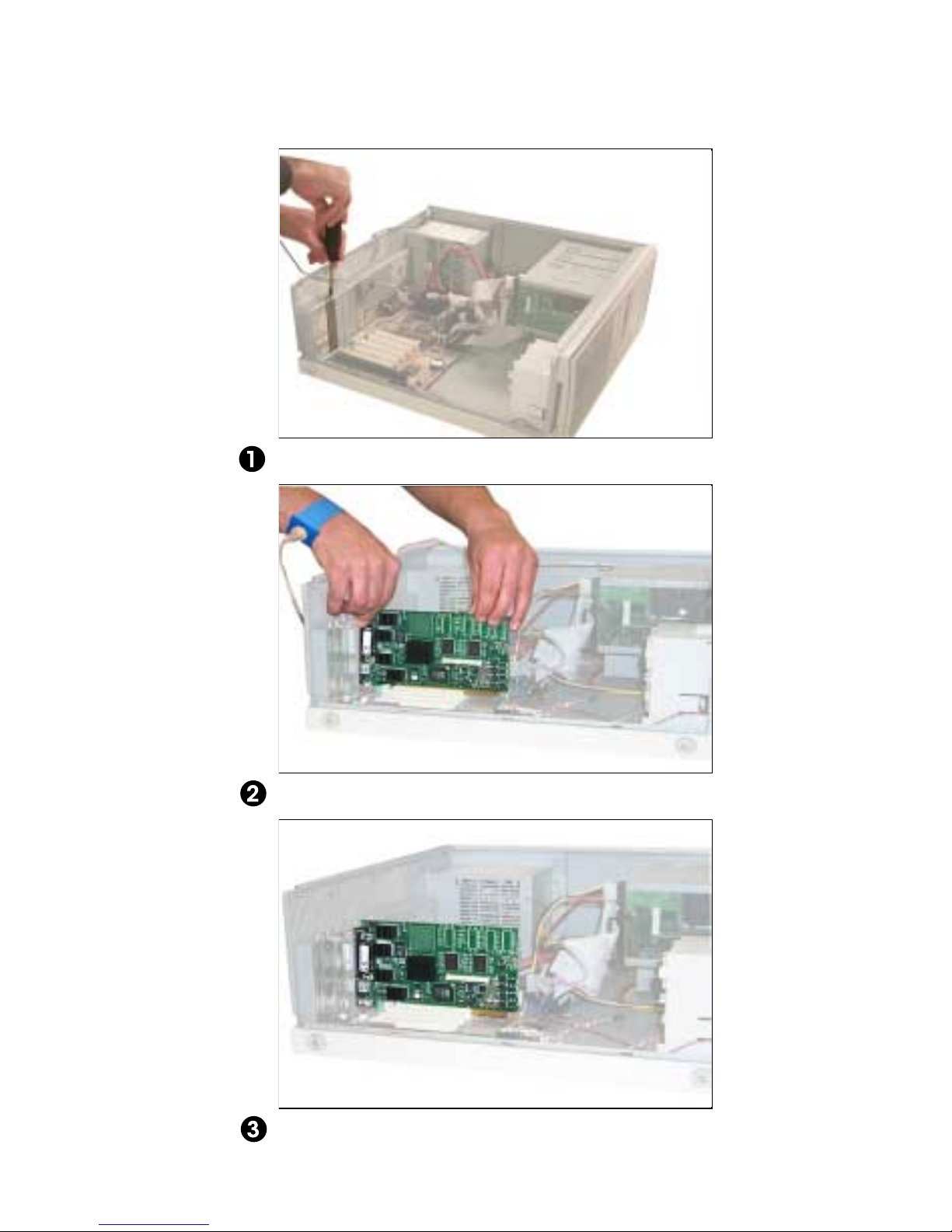
Removing a blank bracket or backplate
Installing the Board |
9
Installing an RX/PCI board
Installed RX/PCI board
Page 20

10
| Installing the Board and Display
Installing multiple boards
Repeat the installation instructions on page 8 for each board.
Remember these tips when you are installing multiple boards:
• You can install as many RX/PCI boards as your system’s
power supply and available PCI slots can support
(Windows 2000, Windows XP, and Solaris).
• The Windows NT driver supports up to eight boards
(16 screens) of the same type. You cannot mix DOME board
types, but you can mix single- and dual-headed boards.
• Each board requires less than 5 amps of +5V.
• For PCs, you must disable VGA mode on all but one RX/PCI
board if multiple boards are in use. See “To disable VGA
mode” on page 6.
• In Sun workstations, you can install different boards in the
same system.
Page 21
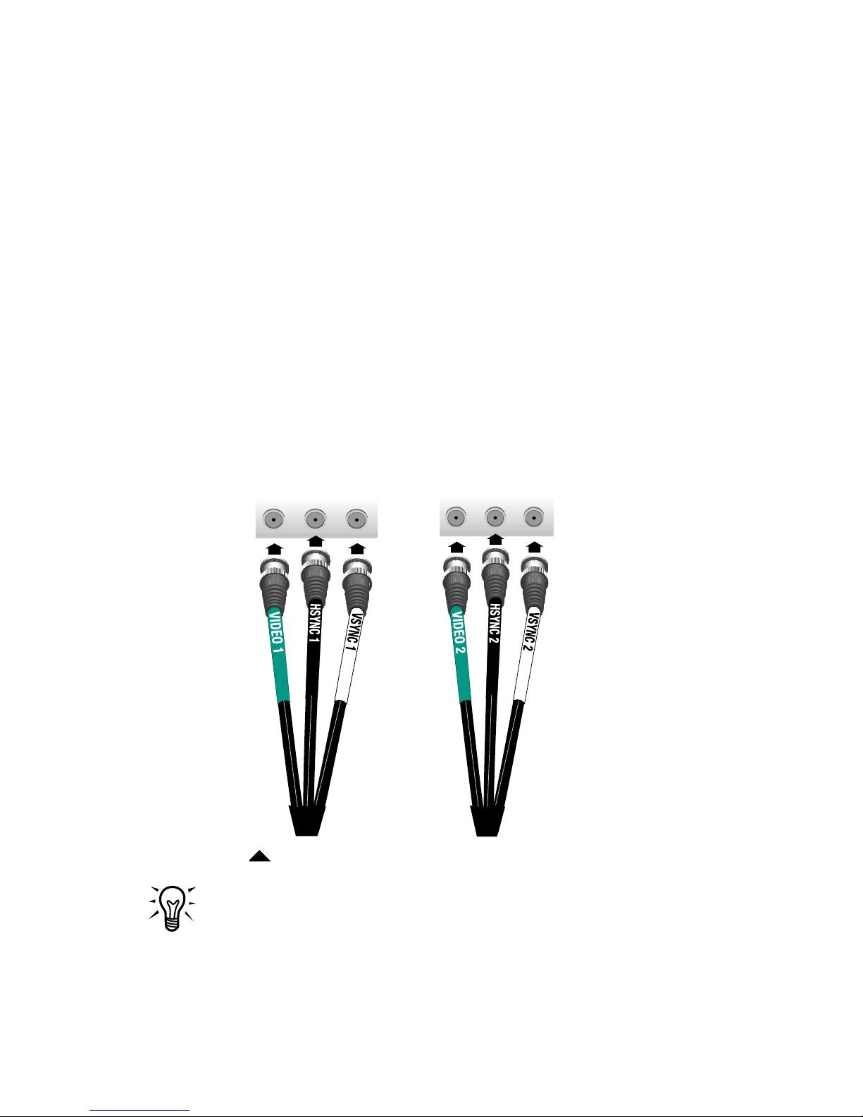
Connecting the Displays
After you install the RX/PCI board, connect the displays to the
board with the cable provided.
To connect the displays to the board
1
Attach the D-shell connector to the RX/PCI board.
Secure the connection with the screws on the connector.
2
Attach each output cable to the appropriate BNC terminal on
your display. (Refer to your display documentation for more
information on connector assignments.)
The cable labeling in this illustration applies to the DOME
RX cable. With a cable from another source, the labeling
may differ.
HSYNC
VIDEO
VSYNC
VIDEO
HSYNC
Connecting the Displays |
VSYNC
11
Connecting the cable to two grayscale displays
If you are using only one display, use the VIDEO1, HSYNC1,
and VSYNC1 connectors.
3
Repeat step 2 for each display that you want to connect
to the RX/PCI board.
Page 22

12
| Installing the Board and Display
To finish the installation
Install the DOME Windows or Solaris driver after you install the
RX/PCI board.
To install this driver... See page...
Windows 2000 (also used by
Windows XP)
Windows NT 29
Solaris 49
13
Page 23

Windows 2000 Driver
Install
before you install the driver initially.
all DOME boards first, then restart your system
Installing the Windows 2000 Driver
Windows XP: The RX/PCI board also supports the
Windows XP operating system. To install the driver for an
XP system, follow the Windows 2000 driver instructions,
using your operating system.
To install the driver
1 Highlight Microsoft Windows 2000 Professional at
startup. Press <F8> during the system boot and select
Enable VGA Mode on the Windows 2000 Advanced
Options menu. Then press <Enter>.
2 Log on with administrator privileges.
The InstallShield Wizard reports that it has found
new hardware.
3 Click Cancel.
4 Insert the WINRX CD, and open 63-WINRX-xxx
(where xxx is a version number).
5 Browse the CD to find the Win2k\RXpci directory.
13
Page 24
14 | Windows 2000 Driver
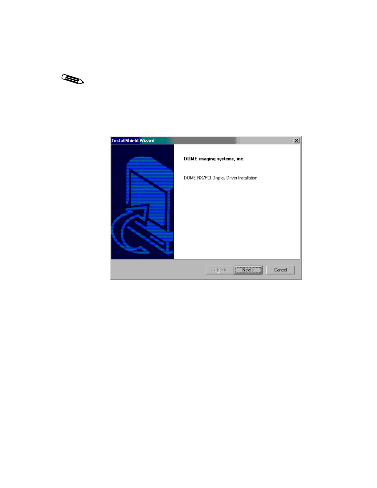
6 Double-click Setup.exe.
The Setup.exe file is an InstallShield Wizard that guides
you through the installation process. Use the DOME
setup function for all DOME installations.
The initial display driver installation dialog box appears.
7 Proceed through the installation (license agreement,
readme files, and start copying files).
8 Click Yes on the Digital Signature Not Found dialog
box to continue the installation.
This dialog box appears for each display you install on
Windows 2000 or XP systems.
Page 25

Installing the Windows 2000 Driver | 15
Windows XP: The RX/PCI driver has not passed
Windows Logo testing to verify its compatibility with
the Windows XP operating system. XP users must click
Continue Anyway on the Hardware Installation dialog
box (equivalent to the Digital Signature Not Found
dialog box) to continue the installation. This dialog box
appears once for each display you install. (The message
occurs only if you have not set your system to shut off
such notices.)
Your display may blink several times during this phase
of driver installation.
A dialog box appears upon completion.
9 Click Finish to exit the Wizard.
Page 26

16 | Windows 2000 Driver
To modify an existing configuration
1 Insert the WINRX CD, and browse to find the
Win2k\RXpci
2 Double-click Setup.exe.
The Welcome dialog box appears.
directory.
3 Select Modify, and click Next.
The Digital Signature Not Found dialog box appears.
4 Click Yes to continue the installation.
The Digital Signature Not Found dialog box appears for
each display you install, and the End of Driver Installation
dialog box appears upon completion.
5 Select Yes, I want to restart my computer now, and
click Finish.
6 Click Finish on the Maintenance Complete dialog box.
The RX/PCI driver loads upon system restart.
Page 27

Installing the Windows 2000 Driver | 17
To install the driver for an additional board
1 Turn off the power to your computer.
Leave the computer plugged into a grounded power outlet
so that the power cord serves as a ground for the computer.
If you leave the computer turned on, you might suffer
electric shock or cause damage to both the computer
components and the RX/PCI board.
2 Disable VGA on the additional board, and install it
following the precautions and installation steps on
pages 8 to 10.
3 Check that all displays are connected and powered on.
4 Log on with administrator privileges.
The Windows Hardware Wizard reports its location of
new hardware and displays the Digital Signature Not
Found dialog box.
For proper installation, you must quit the Wizard and
run the DOME Setup function. This executable installs
the correct number of heads for the new board.
5 Click No to exit the Wizard.
6 Run Setup.exe to modify the existing configuration.
(See steps 2 to 6 on page 16.)
7 Enable your display and set the resolution.
(See page 18.)
Page 28

18 | Windows 2000 Driver
To enable a display and set the display resolution
1 Boot your computer in normal mode.
2 Log on with administrator privileges.
3 Right-click the desktop, and select Properties >
Settings.
4 Click the Display list and select Default Monitor on
DOME RX/PCI,
where X = 4 or 5.
5 Select Extend my Windows desktop onto this monitor,
and click Apply.
This message appears:
Windows will now apply your new desktop settings.
The original desktop will be restored if the
settings are not applied correctly.
6 Click OK to accept the new settings, or Cancel to revert
to the original settings.
If you have installed two or more displays, enable them
as described in steps 3 through 6.
Page 29

Configuring Display Settings
After you install the board and driver and set the default monitor
and refresh rate, you can change the resolution and refresh rate
or any other configuration options.
Use this tab... To set the default monitor and refresh rate for...
DOME tab Displays attached to the Windows 2000 desktop
Configuring Display Settings | 19
Properties >
Settings tab
Displays not attached to the Windows 2000 desktop
The Windows 2000 or XP operating system renumbers and
reassigns screens as they are added to the configuration. Set
resolutions or preferences only after all boards and screens are
installed. Then restart your system to make sure the screen
assignments are stable.
Determining screen assignments
Click Identify in the Settings tab to match screens to boards.
Page 30
20 | Windows 2000 Driver
Using the DOME tab to change display properties
You can change the display properties, such as resolution,
palette options, and brightness, using the DOME tab after
the display is attached to the Windows 2000 desktop.
To change display properties
1 Log on with administrator privileges.
2 Right-click the desktop, and select Properties >
Settings tab.
The Settings tab appears.
3 Select Default Monitor on DOME RX/PCI from the
Display box.
Make sure the Extend my Windows desktop onto this
monitor box is checked.
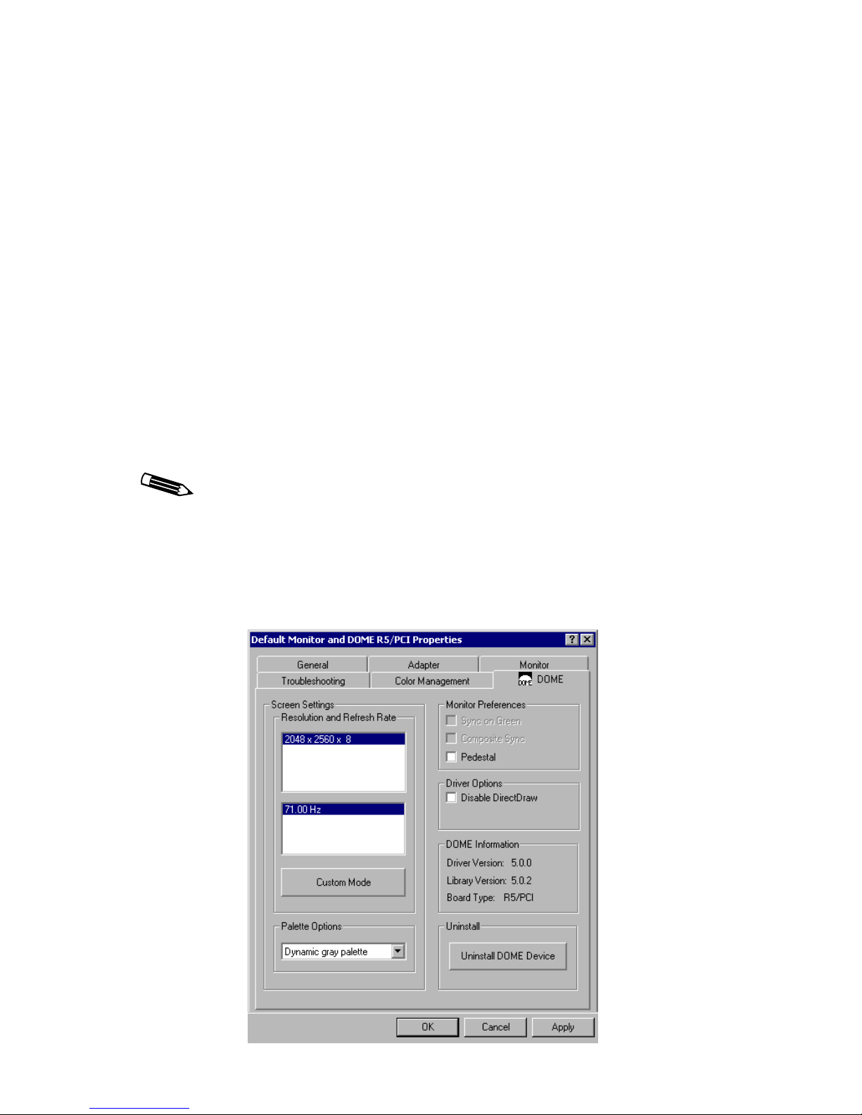
4 Select Advanced > DOME tab to select a resolution and
refresh rate.
The DOME tab appears, similar to the one shown here.
Page 31

Configuring Display Settings | 21
To change the resolution and refresh rate
1 Select a resolution and refresh rate from the DOME tab, and
click Apply.
When you use the DOME tab to set the resolution and
refresh rate for one of the displays of a dual-headed
DOME display board, the second display will assume
the same resolution and refresh rate.
The DOME Display Resolution dialog box appears.
2 Click OK within 15 seconds to accept the new settings.
Ignore the message to revert to the original settings.
The resolution changes on both installed screens, and a
message appears prompting you to accept or cancel the
new resolution.
3 Click OK to set this resolution, or Cancel to return to the
DOME tab.
If you select OK, this message appears.
4 Click OK. You can now use the display.
Page 32

22 | Windows 2000 Driver
To set monitor preferences
To enable Pedestal, select Pedestal on the DOME tab. Refer to
your monitor documentation for more information.
To set driver options
To disable DirectDraw, select Disable DirectDraw on the
DOME tab.
Setting palette options
See Appendix B, “Palette Options for Windows Systems” on
page 75.
To set custom syncs
See “Customizing sync parameters for Windows 2000 or XP” on
page 69.
Page 33

Uninstalling DOME Devices on Windows 2000 | 23
Uninstalling DOME Devices on Windows 2000
You can uninstall DOME devices in either of two ways:
• Uninstall single-headed DOME devices by using the Microsoft
control panel.
• Uninstall dual-headed DOME devices by clicking Uninstall
DOME Device on the DOME tab, and then by removing the
device through the Microsoft control panel. Make sure you
remove the sister device first.
Remember these tips when uninstalling DOME devices:
• You can uninstall both single- and dual-headed DOME
display boards.
• The device that you are uninstalling cannot have system
resources if its sister display is installed.
• The device that you are uninstalling must be attached to the
Windows 2000 desktop.
• You cannot uninstall the primary display.
To uninstall a single-headed DOME device
1 Select Start > Settings > Control Panel >
Administrative Tools icon.
2 Click Computer Management.
The Systems Tools dialog box appears.
3 Click Device Manager.
Page 34

24 | Windows 2000 Driver
4 Click Display Adapters.
A list of currently installed display devices appears.
5 Highlight the adapter you want to remove. Right-click and
choose Uninstall.
6 Click OK in the Confirm Device Removal dialog box.
The Systems Settings Change dialog box appears.
7 Click Yes to restart your computer.
The device is now removed from Windows 2000.
8 Turn off your computer after it restarts, and remove the
RX/PCI board.
Page 35

Uninstalling DOME Devices on Windows 2000 | 25
Uninstalling a dual-headed DOME device
You must uninstall a dual-headed DOME device on a
display-by-display basis. Uninstall the sister device first
and the primary device second.
The DOME control panel determines if you are uninstalling the
devices in the proper order.
To uninstall a device in the proper order
1 Use the Uninstall DOME Device button on the DOME tab to
begin uninstalling a dual-headed DOME device.
2 Use the Windows 2000 device-removal method to finish
uninstalling a dual-headed DOME device.
To uninstall a dual-headed DOME device
1 Right-click on the desktop, select Properties > Advanced for
the sister device.
2 Select DOME tab > Uninstall DOME Device button.
You are prompted to restart the computer.
3 Restart your computer.
Once you restart your computer, the sister device no
longer appears in Windows Display Properties.
4 Select Start > Settings > Control Panel >
Administrative Tools icon.
5 Click Computer Management.
The Systems Tools dialog box appears.
6 Click Device Manager.
Page 36

26 | Windows 2000 Driver
7 Click Display Adapters.
A list of currently installed display devices appears.
8 Highlight the adapter that is illustrated with the Display
Warning icon. Right-click and choose Uninstall.
9 Click OK in the Confirm Device Removal dialog box.
The device is now removed from Windows 2000.
10 Restart your computer.
To finish uninstalling the initial device of the dual-headed
DOME display board, follow the steps in “To uninstall a
single-headed DOME device” on page 23.
Page 37

Uninstalling DOME Devices on Windows 2000 | 27
Using Calibration TQA on Windows 2000
DOME Calibration TQA 2.1 or later supports all combinations
of bit depths and palette options currently supported by
DOME drivers.
You can run Calibration TQA 2.1 or later on a system that
includes both DOME and other brands of boards.
Do not change Windows display settings while Calibration TQA
is running. Calibration TQA and other mdpcint.dll-reliant
applications behave unpredictably if you make changes while
the application is active.
Page 38

Page 39

Windows NT 4.0 Driver
Install all DOME boards first, then restart your system
before you install the driver initially.
Installing the Windows NT 4.0 Driver
To install the driver
1 Turn on the computer and select Windows NT Workstation
Version 4.00 [VGA mode].
2 Log on as administrator.
You need administrator privileges to change the
display settings.
3 Select Start > Settings > Control Panel >
Display > Settings.
29
Page 40

30 | Windows NT 4.0 Driver
The Settings tab appears.
4 Click Display Type….
The Display Type dialog box appears.
5 Click Change… in the Adapter Type section of the
dialog box.
The Change Display dialog box appears.
6 Click Have Disk….
The Install From Disk dialog box appears, containing
this field:
Copy manufacturer’s files from:
A:\
7 Insert the WINRX CD and browse to the
WinNT4\RXPCI\r5xci.4.4.x.yyy d
irectory
(where x.yyy denotes version number).
8 Find and select the oemsetup.inf file, and click Open….
Page 41

Installing the Windows NT 4.0 Driver | 31
9 The Change Display dialog box appears, with these options:
DOME imaging systems R4/PCI
DOME imaging systems R5/PCI
10 Select the desired driver, and click OK.
The Third-party Drivers dialog box appears, prompting you:
Do you wish to proceed?
11 Click Yes.
A progress bar appears. Then the Installing Driver dialog box
appears with this message:
The drivers were successfully installed.
12 Click OK, then click Close on the Display Type dialog box
and on the Display Properties dialog box.
The System Settings Change dialog box appears,
prompting you:
Do you want to restart your computer now?
13 Click Yes.
14 Select Windows NT Workstation Version 4.00 [VGA mode],
and then configure your display settings as described in the
next section.
Page 42

32 | Windows NT 4.0 Driver
Configuring Display Settings
After you install the board and driver in your system, set the
display resolution and refresh rate. You can then update any
other configuration options.
To set the display resolution and refresh rate
1 Log on as administrator.
The Invalid display settings dialog box displays.
2 Click OK.
The Settings tab appears.
3 Click List All Modes….
Page 43

Configuring Display Settings | 33
The Detected Adapter dialog box appears.
The dialog box on your screen displays the values that exist
in your binary .cfg file, which may be different from the
values displayed in this illustration. For information on
editing these values, see “Customizing sync parameters for
Windows NT” on page 68.
4 Select the resolution and refresh rate, and click OK.
5 Click Test.
Your display(s) must be connected to test the resolution and
refresh rate.
The Testing Mode dialog box appears with this message:
The new mode will be tested. Your graphics adapter
is set to the new mode temporarily so that you can
determine whether it works properly. Click OK and
then wait 15 seconds.
6 Click OK.
A test bitmap appears.
The Testing Mode dialog box appears, prompting you:
Did you see the test bitmap properly?
Page 44

34 | Windows NT 4.0 Driver
7 Click Yes if the test bitmap displayed correctly or No if it
displayed incorrectly.
If No, the Testing Mode dialog box appears, prompting you
to try different settings for your display. Click OK. Repeat
steps 3–7 to perform the test with a different resolution.
8 Select Large Fonts in the Font Size field (optional).
Selecting Large Fonts on the Settings tab does not
make a significant difference in font size at very high
resolutions. The DOME driver installs extra-large font
options in your C:\dome\tools directory. To add
those fonts to your display properties, follow the
instructions for “DOME large fonts” on page 40.
9 Click OK.
The display resolution is now set properly for the
RX/PCI board.
This message appears:
Do you want to restart your computer now?
10 Click No.
You can now change your display properties using
the DOME tab.
11 Select Start > Settings > Control Panel > Display > DOME.
A dialog box prompts you to choose a configuration file
(because the system is currently in VGA mode).
12 Click Open to use the default configuration file (mxpci.cfg)
on your system.
The DOME tab appears.
You can make several changes to your display settings
at one time. See the next section, “Using the DOME tab
to change display properties.”
Page 45

Configuring Display Settings | 35
13 Click OK or Apply when you have selected all the new
settings and want them to take effect.
This message appears:
Do you want to restart your computer now?
14 Click Yes.
The system prompts you to select an operating system.
15 Select Windows NT Workstation 4.00 and then change your
display settings as described in the next section.
Using the DOME tab to change display properties
Use the DOME tab to change the display properties listed in the
following table.
To complete this task… See page…
Change the resolution and refresh rate 37
Set the screen configuration 37
Select palette options 75
Set monitor preferences 38
Set driver options 38
Page 46

36 | Windows NT 4.0 Driver
To use the DOME tab
1 Select Start > Settings > Control Panel >
Display > DOME.
The DOME tab appears.
2 Select the desired display properties, and then click Apply.
3 Restart your computer to display the changes.
To use the DOME tab online help
The Windows NT driver provides online context-sensitive help
for the DOME tab. You can access the help in either of two ways:
• Click the question mark (?) button on the title bar and then
click the area of the DOME tab with which you need
assistance.
• Move the cursor to the area with which you need assistance
and then press <F1>.
Page 47

Configuring Display Settings | 37
To change the resolution and refresh rate
1 Highlight the desired resolution and refresh rate in the
Resolution and Refresh Rate fields.
2 Click Apply or OK.
This dialog box appears, indicating that the new
settings are being tested.
3 Click OK within 15 seconds to accept the new settings.
Ignore the message to revert to the original settings.
To set the screen configuration
Click the screen number and orientation in the Configuration
field, and then click Apply or OK.
The screens are assigned to the boards in the order in
which the boards are found on the bus. If the first board is
a dual-headed board, it controls screens zero (0) and one (1).
Page 48

38 | Windows NT 4.0 Driver
Setting palette options
See Appendix B, “Palette Options for Windows Systems” on
page 75.
Setting monitor preferences
These monitor preferences are available on the DOME tab:
• Sync on Green
• Pedestal
• Composite Sync
Refer to your monitor documentation for more information on
monitor preferences.
Setting the driver options
The driver option DirectDraw is available on the DOME tab.
Click Disable DirectDraw on the DOME tab to turn off this
feature. Click again to turn on.
DirectDraw and multiheaded support
DirectDraw™ is an Application Program Interface (API) that
allows direct manipulation of the video display. DirectDraw
applications expect the screen to be represented as a single
element. If you are using multiple RX/PCI screens, more
than one screen represents the desktop.
With multiple displays representing the desktop, DirectDraw
applications cannot access the entire desktop and may not
work properly.
Page 49

Configuring Display Settings | 39
DirectDraw limited screen size
Under the Windows NT 4.0 operating system, Build 1381,
DirectDraw supports screen sizes only up to 2048 x 2048 pixels.
DirectDraw applications may not work correctly with bigger
screen sizes. Although DOME has tried to provide whatever
support possible within this limitation, DOME cannot ensure
DirectDraw compatibility with either multiple screens or a
screen size greater than 2048 x 2048 pixels.
Microsoft has fixed this problem in Windows 2000 and later
operating systems.
Page 50

40 | Windows NT 4.0 Driver
Additional Display Settings
This section describes additional display settings offered on the
DOME tab.
DOME large fonts
The Windows NT 4.0 driver uses standard Windows fonts. The
DOME driver supplements these fonts with three large fonts that
support high-resolution display. The DOME Windows NT 4.0
driver installs those fonts in the C:\dome\tools directory.
Installing DOME large fonts does not automatically increase the
size of your cursor. See “To increase the cursor size” on page 41
for instructions.
To install DOME large fonts
1 Double-click My Computer > C: > DOME > Tools.
A list of files appears.
2 Double-click the desired font:
• DOME large
• DOME extra large
• DOME extra extra large
3 Close all applications and windows.
4 Restart your computer.
5 Select Start > Settings > Control Panel >
Display > Appearance.
The Appearance tab appears.
6 Click the Scheme pull-down arrow, and select the font.
7 Click OK.
Page 51

Additional Display Settings | 41
To uninstall DOME large fonts
1 Double-click My Computer > C: > DOME > Tools.
A list of files appears.
2 Double-click WinStand.reg.
3 Click OK.
4 Close all applications and windows.
5 Restart your computer.
6 Select Start > Settings > Control Panel >
Display > Appearance.
7 Click the Scheme pull-down arrow, and select
Windows Standard.
8 Click OK.
To increase the cursor size
1 Select Start > Settings > Control Panel >
Mouse > Pointers.
The Pointers tab appears.
2 Click the Scheme pull-down arrow, and select
Windows Standard (extra large).
3 Click OK.
4 Close the Control Panel dialog box.
To r eturn to the standard cursor size, follow steps 1–4 of
this procedure, and select Windows Standard from the
Scheme drop-down box.
Page 52

42 | Windows NT 4.0 Driver
To customize item and font size
Use the Display Properties dialog box to adjust both your
system- and application-level font sizes to compensate for
high-resolution display. You can also customize font
appearance and icon, menu, and title bar size.
This table provides recommended font and icon sizes for
high-resolution displays.
This
selection…
Controls font and
size of this item…
Active Title Bar Active window title
bar
Icon Icons on the
desktop
b
Menu All menus, both
system- and
application-level
Message Box All message box
text
Tool Tip All tool tip text, both
system- and
application-level
Default
settings are…
Item size: 18
Font size: 8
Item size: 32
Font size: 8
Item size: 18
Font size: 8
Item size: n/a
Font size: 8
Item size: 18
Font size: 8
Recommended
settings are…
a
Item size:
-Font size: 10 or
12
Item size:48
Font size: 10
Item size:
a
-Font size: 10 or
12
Item size: n/a
Font size: 10 or
12
Item size: -Font size: 10 or
12
a. The item size adjusts automatically if the font size changes.
b. If the item or font size is too large, the icon and text may be cropped. If
this occurs, adjust icon spacing by right-clicking on the desktop and choosing
Line Up Icons or Arrange Icons. You can also change icon spacing by
choosing Icon Spacing (Horizontal) and Icon Spacing (Vertical), and
adjusting the size setting to a larger number. (The default spacing is 43.)
Page 53

DOME DlgFix software
DOME DlgFix software automatically relocates all dialog boxes
to the upper-left screen, preventing dialog boxes from splitting
across screens.
Additional Display Settings | 43
Dialog box splits across screens when DlgFix is not running
Dialog box displays in upper-left screen when DlgFix is running
DOME
DlgFix software is copied to C:\dome\tools
automatically during Windows NT 4.0 driver installation.
Page 54

44 | Windows NT 4.0 Driver
Limitations of DlgFix
Because of limitations in the Windows NT operating system,
DlgFix
the Startup programs. The logon dialog boxes are still split
between screens.
To run DlgFix
Type C:\dome\tools\DlgFix at the DOS prompt.
The DOME DlgFix icon appears on your taskbar to indicate that
DlgFix
To add DlgFix to the startup menu
Type C:\dome\tools\DlgSetup at the DOS prompt.
cannot modify dialog box locations until you run
is running.
Once you type this command, DlgFix automatically restarts
each time you restart your computer.
To uninstall DlgFix
Type C:\dome\tools\DlgUnins at the DOS prompt.
Your system will experience a slight performance degradation
while running DlgFix. If you find system performance
unacceptable, uninstall the software as indicated above.
DOME DPMS Screen Saver for Windows NT
Display Power Management Signaling (DPMS) provides a standard way to manage the power used by a display. With DPMS,
you can shut off the video signal to the display when it is not in
use, thereby extending the life of your display’s CRT or backlight
and reducing its power consumption.
The DOME DPMS Screen Saver for Windows NT is a powerful
and flexible way to increase your display’s life and decrease its
power consumption.
Page 55

Additional Display Settings | 45
How the screen saver works
Like other Windows screen savers, the DOME DPMS Screen
Saver is invoked after the system has received no user input for a
specified number of minutes. Unlike other screen savers, however, the DOME DPMS Screen Saver does not display anything
on the screen itself. Rather, it launches another screen saver that
you select to protect the display. Then, after a predetermined
number of minutes, it uses DPMS to shut off the video power to
the display.
There are two delay periods before DPMS is invoked.
• The first delay is the standard screen saver delay from the
last user input until the screen saver launches.
• The second delay is from the time the screen saver launches
until DPMS shuts off the video power to the display. After
the second delay, DPMS places the display in power-off mode.
The DOME DPMS Screen Saver allows you to select the other
screen saver to use before it invokes power-off mode. It also
allows you to specify up to four periods during the day and
different settings for when or if power-off mode is invoked
during each period.
Page 56

46 | Windows NT 4.0 Driver
To select the DOME DPMS Screen Saver
1 Select Start > Settings > Control Panel >
Display > Screen Saver.
The Screen Saver tab appears.
2 Select DOME DPMS Screen Saver.
3 Set the Wait: field with the delay time until you want the first
screen saver to appear.
Page 57

Additional Display Settings | 47
To set up the DOME DPMS Screen Saver
1 Click Settings….
This dialog box appears.
2 Select a Screen Saver from the list of available screen savers.
The screen saver you select will appear on your display
before DPMS power-off mode is invoked. You can select
any of the other installed Windows screen savers to protect
the display during that time. The Settings and Preview buttons enable you to adjust the screen saver settings and see
a sample of what each looks like.
You can create as many as four distinct periods throughout
the day, with different DPMS settings for each period.
Continue this procedure to set each time period.
3 Set the start time in the Starting at: field.
Page 58

48 | Windows NT 4.0 Driver
Use a 24-hour time format, such as 16:30 to indicate 4:30 p.m.
This determines if or when power-off mode will be invoked
for up to four different periods of the day.
One period ends when the next period starts.
Leave the start time for a period blank if you don’t want
to use it.
4 Enter the number of minutes of additional inactivity (after
the first screen saver displays) until the display is placed in
power-off mode in the Invoke DPMS after: field.
5 If desired, select Wake at start of period to force the display
to wake up if it is in power-off mode at the start of the period.
6 If desired, select Never sleep during this period to prevent a
switch to power-off mode during the period.
7 Click OK to keep your settings.
The Display Properties dialog box appears.
8 Click OK.
Remember these tips when you set the screen saver:
• The two delay periods are cumulative. If it takes 15 minutes of
user inactivity for the DOME DPMS Screen Saver to start, and
there is a 30-minute delay until power-of f mode is invoked for
the current time period, power-off mode starts only after a
total of 45 minutes of user inactivity.
• After the display has been in power-off mode for a long time,
it can take as many as 30 minutes to reach optimal performance conditions when the video power is turned on again.
To ensure that the display is performing optimally when you
need it, use the DOME DPMS Screen Saver to force the
display to wake up before periods of heavy use begin.
Page 59

Solaris Driver
Install all DOME boards before you install the driver initially.
Then reboot your system.
Installing the Solaris Driver
Installing the RX/PCI driver for your Sun host requires about
500 KB of free space:
• 200 KB in /kernel/drv
• 100 KB in /usr/openwin/server/modules
• 200 KB in /usr/lib
The installation procedure for Solaris performs these tasks:
• Adds the device driver
• Adds the OpenWindows™ loadable DDX driver
• Modifies the OWconfig file
• Installs the DOMEmdlib shared object library
To install the driver
1 Turn on your workstation.
2 Boot up with the -r option.
3 Log on as root.
49
Page 60

50 | Solaris Driver
This installation procedure uses the R5/PCI driver
as an example. When you install the R4/PCI driver,
the package name will be DOMEr4pci instead of
DOMEr5pci
.
If a previous version of the driver software exists on
your system, you must remove it before you install the
new package. To do so, type pkgrm, and select the
DOMEr5pci and DOMEmdlib packages for removal. If
the DOMEmdlib package already installed on the system
is newer than that on the CD, do not remove it.
4 Insert the DOME RX/PCI Solaris driver CD in the
CD drive.
5 Mount the CD device if the system does not automount it.
Then type:
cd /cdrom/dome
6 To transfer the software packages to the system, type:
pkgadd -d r5pciZZZ.pkg
where ZZZ=revision of the software on the CD.
Check the file name on the CD to get the software revision.
This message appears:
The following packages are available:
1 DOMEr5pci DOME R5PCI Display Support
(sparc) 1.2.x
2 DOMEmdlib DOME MD library
(sparc) 1.0.x
Select package(s) you wish to
process (or 'all' to process all
packages). (default:all)[?,??,q]:
7 Press <Return> to install all packages or the number 1 (one)
to install the DOMEr5pci package only.
Page 61

Installing the Solaris Driver | 51
Messages appear, followed by this prompt:
Do you want to continue with the installation of the
package [y,n,?]
8 Type y.
Messages describe the progress of the installation. When the
installation is complete, these messages appear:
Installation of <DOMEmdlib> was successful.
Installation of <DOMEr5pci> was successful.
You do not need to reboot your system.
Page 62

52 | Solaris Driver
Configuring Display Settings
Before you configure your system for the Sun Common Desktop
Environment (CDE) or OpenWindows, you must set the display
mode for your board. DOME provides a default display mode
that you can either use or override as described in this section.
Read the following sections before you configure CDE or
OpenWindows:
• “Using the default display mode” (page 52)
• “Overriding the default display mode” (page 52)
• “Using Visual Classes” (page 56)
Then read the appropriate section for your windowing
environment:
• “To run OpenWindows” (page 60)
• “To configure CDE” (page 61)
Using the default display mode
DOME configures RX/PCI boards with default display modes
before shipment. When you use the RX/PCI board as the boot
console, you must connect the board to a display capable of using
this default mode. See “Changing the Console” on page 65 for
information about making the RX/PCI board the console.
This table shows the default display mode for each board.
Board Default Display Mode
R4/PCI 1728 x 2304 pixels @ 69 Hz
R5/PCI 2048 x 2560 pixels @ 71 Hz
Overriding the default display mode
To start CDE or OpenWindows using the default display mode,
skip this section.
Page 63

Configuring Display Settings | 53
Edit the OWconfig file to override the default display mode and
customize your configuration for both CDE and OpenWindows.
This file exists in the /usr/openwin/server/etc and in the
/etc/openwin/server/etc
directory on the workstation. Edit
the one in the /etc/openwin/server/etc directory.
To edit the OWconfig file
When you install a new driver on your system, it overwrites the
OWconfig
OWConfig file in the /etc/openwin/server/etc directory
remains unchanged. This ensures that the changes you make
are not overwritten when you update to newer versions of
the DOME driver. Make sure you edit these lines in the
/etc
directories, your system ignores them.
file in this directory: /usr/openwin/server/etc. The
directory only. If you uncomment these lines in both
1 Find the following lines in the OWconfig file:
#class = "XSCREENCONFIG" name="DOMEr5pci0Config"
# device="/dev/r5pci0.0"
# res="2048x2560 @ 71Hz"
# monitor="domegray.vda"
# board="r5pci-2hd.xqa";
#class = "XSCREENCONFIG" name="DOMEr5pci1Config"
# device="/dev/r5pci0.1"
# res="2048x2560 @ 71Hz"
# monitor="domegray.vda"
# board="r5pci-2hd.xqa";
For one-headed R5/PCI boards, you need only the first
five lines.
This procedure uses the R5/PCI driver as an example.
When you install the R4/PCI driver, the name will be
DOMEr4pci
instead of DOMEr5pci.
2 Delete the pound sign (#) at the beginning of each line to
uncomment the lines.
3 Edit the lines to match each device you installed, and save
your changes.
Page 64

54 | Solaris Driver
Modifying the OWconfig file
This section explains the first example from the preceding
sample code, line by line, and tells how to modify those
lines to match the devices you are installing.
class="XSCREENCONFIG" name="DOMEr5pci0Config"
The name provided here must be unique in the OWconfig file.
You can alter it as long as you select a name that is not being
used for any other XSCREENCONFIG sections.
device="/dev/r5pci0.0"
This line indicates that the board is an R5/PCI board that was
assigned the instance of zero (0) by the system. The second zero
(0) indicates that you are using the first head. To modify this line
for the device you are installing, replace the first zero (0) with the
instance your board was assigned by the system. For the second
head, replace the second zero (0) with a one (1).
res="2048x2560 @ 71Hz"
This line indicates that your display’s resolution
(preadjusted timing name) is 2048 x 2560 @ 71 Hz.
When you modify this line, be sure to use the exact name for
your display from the “Preadjusted Timing Name” column in
the Resolutions and Refresh Rates table on page 73.
monitor="domegray.vda"
This line indicates that you are using a grayscale display, and
the preadjusted timing name is located in the display file
domegray.vda
Display files are located in the
.
/opt/DOMEr5pci/monitors
directory. Do not modify these files unless DOME Customer
Support advises you to do so.
To support a color display, use "domecolr.vda" instead of
"domegray.vda."
Page 65

Configuring Display Settings | 55
board="r5pci-2hd.xqa"
This line indicates that you are using two heads (-2hd) of an
R5/PCI board (r5pci), and that the configuration of the board is
located in the board file r5pci-2hd.xqa.
The board file is located in the /opt/DOMEr5pci/boards
directory. Do not modify this file.
See the second code sample on page 53 for configuration for the
second head.
To enable video pedestal
Set the BlackLevel parameter in the domegray.vda
file to 0.054.
To disable video pedestal
Set the BlackLevel parameter to 0.0.
Page 66

56 | Solaris Driver
Using Visual Classes
A visual class (or visual) is the X Window System™ terminology
to describe the characteristics of a display. X defines the visual
classes listed in this table.
Static Class Dynamic Class
• StaticGray • GrayScale
• StaticColor • PseudoColor
• TrueColor • DirectColor
Static classes do not support the use of a modifiable colormap,
but the corresponding dynamic classes do.
The RX/PCI board has a default visual class of GrayScale.
PseudoColor is the most common display type. Some
applications run only on displays with a PseudoColor default
visual class. You can configure the RX/PCI board to emulate
PseudoColor
for applications by invoking the X Window
System with PseudoColor as the default visual class.
Page 67

Using Visual Classes | 57
To emulate a PseudoColor visual class
Start the X server using PseudoColor as the default visual class
by adding defclass PseudoColor to the openwin command
and to the Xservers file.
For example, for a one-headed system using the R5/PCI
board, type:
openwin -dev /dev/r5pci0.0 defclass PseudoColor
For a two-headed system using the R5/PCI board, type:
openwin -dev /dev/r5pci0.0 defclass PseudoColor \
-dev /dev/r5pci0.1 defclass PseudoColor
When you edit or modify code, type it on one line.
A backslash (\) indicates continuation of the line.
To check the default visual
Use the xdpyinfo command to check the default visual of a
screen. Look at the correct screen and find the visual with the
matching ID to verify that it is PseudoColor.
Look for the lines marked with a right arrow (➞) in this
sample output:
name of display: cole:0.0
version number: 11.0
vendor string: Sun Microsystems, Inc.
vendor release number: 3300
maximum request size: 262140 bytes
motion buffer size: 256
bitmap unit, bit order, padding: 32, MSBFirst, 32
image byte order: MSBFirst
number of supported pixmap formats: 2
supported pixmap formats:
depth 1, bits_per_pixel 1, scanline_pad 32
depth 8, bits_per_pixel 8, scanline_pad 32
keycode range: minimum 8, maximum 132
focus: window 0x280000d, revert to PointerRoot
number of extensions: 12
SUN_ALLPLANES
SHAPE
Page 68

58 | Solaris Driver
Look ➞ default visual id: 0x22
for visual:
these ➞ visual id: 0x22
lines ➞ class: PseudoColor
MIT-SHM
Multi-Buffering
XInputExtension
XInputDeviceEvents
XTEST
MIT-SUNDRY-NONSTANDARD
SUN_DGA
Adobe-DPS-Extension
DPSExtension
X3D-PEX
default screen number: 0
number of screens: 1
screen #0:
dimensions: 1152x900 pixels
(325x254 millimeters)
resolution: 90x90 dots per inch
depths (2): 1, 8
root window id: 0x29
depth of root window: 8 planes
number of colormaps: minimum 1, maximum 1
default colormap: 0x21
default number of colormap cells: 256
preallocated pixels: black 1, white 0
options: backing-store YES, save-unders YES
current input event mask: 0xd0001d
KeyPressMask ButtonPressMask ButtonReleaseMask
EnterWindowMask SubstructureRedirectMask
PropertyChangeMask ColormapChangeMask
number of visuals: 6
depth: 8 planes
size of colormap: 256 entries
red, green, blue masks: 0x0, 0x0, 0x0
significant bits in color specification: 8 bits
visual:
visual id: 0x23
class: DirectColor
depth: 8 planes
size of colormap: 8 entries
red, green, blue masks: 0x7, 0x38, 0xc0
significant bits in color specification: 8 bits
visual:
Page 69

Using Visual Classes | 59
visual id: 0x24
class: GrayScale
depth: 8 planes
size of colormap: 256 entries
red, green, blue masks: 0x0, 0x0, 0x0
significant bits in color specification: 8 bits
visual:
visual id: 0x25
class: StaticColor
depth: 8 planes
size of colormap: 256 entries
red, green, blue masks: 0x7, 0x38, 0xc0
significant bits in color specification: 8 bits
visual:
visual id: 0x26
class: TrueColor
depth: 8 planes
size of colormap: 8 entries
red, green, blue masks: 0x7, 0x38, 0xc0
significant bits in color specification: 8 bits
visual:
visual id: 0x27
class: StaticGray
depth: 8 planes
size of colormap: 256 entries
red, green, blue masks: 0x0, 0x0, 0x0
significant bits in color specification: 8 bits
number of mono multibuffer types: 6
visual id, max buffers, depth: 0x22, 0, 8
visual id, max buffers, depth: 0x23, 0, 8
visual id, max buffers, depth: 0x24, 0, 8
visual id, max buffers, depth: 0x25, 0, 8
visual id, max buffers, depth: 0x26, 0, 8
visual id, max buffers, depth: 0x27, 0, 8
number of stereo multibuffer types: 0
Page 70

60 | Solaris Driver
Configuring the Windowing Environment
Once you have set the display mode, configure your system to
run either the OpenWindows or CDE windowing environment.
To run OpenWindows
For a one-headed system, type:
openwin -dev /dev/r5pci0.0
For a two-headed system, type:
openwin -dev /dev/r5pci0.0 -dev /dev/r5pci0.1
Each screen has a name of the form:
/dev/r5pciy.z
where
y= board instance
z= head number (0 for first head, 1 for second head)
Board instances are assigned by the system.
For more information on openwin, refer to your Sun
OpenWindows documentation.
Page 71

Configuring the Windowing Environment | 61
To configure CDE
If you are using CDE as your windowing environment,
configure it for your R5/PCI board as described below.
CDE defaults to using a single framebuffer associated
with /dev/fb, the boot console. To change the startup
configuration, copy the /usr/dt/config/Xservers file to
/etc/dt/config/Xservers, and edit it there.
This file contains mostly comments, but the last line is the
command line used to start the X server and bring up CDE.
This is the default line:
:0 Local local_uid@console root /usr/openwin/bin/Xsun \
:0 -nobanner
When you modify this code, type it on one line. The backslash
(\) indicates continuation of the line.
To use one or more DOME devices
Replace the second :0 with the -dev option flag and the
appropriate device parameter.
For example, to use both heads of an R5/PCI board, change the
line to:
:0 Local local_uid@console root /usr/openwin/bin/Xsun \
-dev /dev/r5pci0.0 -dev /dev/r5pci0.1 -nobanner
If you need to use a different default visual class, add the appropriate defclass option for each -dev option. See “Using Visual
Classes” on page 56.
To use a DOME device with a Sun console
Change the line to:
0 Local local_uid@console root/usr/openwin/bin/Xsun \
-dev /dev/fb -dev /dev/r5pci0.0 -nobanner
Page 72

62 | Solaris Driver
Using the DPMS Screen Saver with CDE
When you are running Solaris 2.5.1 or later, CDE allows you to
enable a Display Power Management Signaling (DPMS) screen
saver. DPMS provides a standard way to manage the power used
by your display. DPMS shuts off the video signal to the display
when it is not in use, thereby extending the life of your display’s
CRT or backlight and conserving energy.
You can enable DPMS through the Style Manager, just as you
would invoke any screen saver. You can also turn off DPMS to
prevent your screen from powering off during times when you
are using the display frequently.
To set the DPMS Screen Saver for your display
1 Click the Style Manager.
The Style Manager dialog box appears.
2 Click Screen.
Page 73

Configuring the Windowing Environment | 63
The Style Manager – Screen dialog box appears.
3 Click On in the Screen Saver field to turn on a screen saver.
4 Select Blank Screen from the list of screen savers at the left.
If you select any screen saver other than or in addition to
Blank Screen, the system does not invoke DPMS. Instead,
it uses the screen saver you selected.
5 Use the slider in the Start Saver field to set the time from
when the system last received input on the mouse or key-
board until the system invokes the screen saver. You can
set this time from 1 (one) to 120 minutes.
Page 74

64 | Solaris Driver
Remember these tips when you set the screen saver:
• During times that you are using the display frequently, make
sure you set the Screen Saver field to Off. This setting ensures
that the display does not invoke DPMS, which means that you
do not have to wait for the display to stabilize when you begin
to use it again.
• Set the Screen Saver field to On when you will be away
from the computer for several hours.
Page 75

Changing the Console
The console appears on the first head on the first board in the
system’s probe list by default. You can change the console with
the pci-probe-list environment variable. If you want to
change the console without changing the probe list, change the
output-device
Use the setenv command to change environment variables.
To use the setenv command
1 Power on or halt the system to get to the ok> prompt.
2 Type:
setenv output-device <device node>
environment variable instead.
Changing the Console | 65
The device node portion of the setenv command differs
for different Sun systems and board locations.
These examples describe how to change the console in
Ultra 10 and Ultra 30 systems. For more details, refer to
your Sun documentation.
3 To make the R5/PCI board the console in an Ultra 10
system, type:
setenv output-device /pci/DOME,R5PCI
For an Ultra 30 system, which has two PCI buses, type:
setenv output-device /pci@X/DOME,R5PCI
where X is the location of the board.
For example, if the board is located at location
1f,4000
setenv output-device /pci@1f,4000/DOME,R5PCI
, type:
4 Reboot the system.
Page 76

Page 77

w
Resolutions and Refresh Rates
This appendix lists the RX/PCI resolutions and refresh rates for
PCs and Sun PCI workstations.
Resolutions and Refresh Rates for PCs
The resolutions and refresh rates available for the R5/PCI and
R4/PCI boards in PCs are listed in this table.
Resolution
(width x height)
a
Vertical
Refresh Rate
Boards
Supported
2048 x 2560 portrait 71 Hz R5/PCI
2048 x 2560 portrait 65 Hz R5/PCI
2048 x 2560 portrait
b
71 Hz R5/PCI
2048 x 2560 portrait 76 Hz R5/PCI
2560 x 2048 landscape 69 Hz R5/PCI
1728 x 2304 portrait 69 Hz R4/PCI, R5/PCI
1728 x 2304 portrait 63 Hz R4/PCI, R5/PCI
1536 x 2048 portrait 70 Hz R4/PCI, R5/PCI
2048 x 2048 landscape 60 Hz R4/PCI, R5/PCI
a. In pixels.
b. Extended vertical blanking.
67
Page 78

68 | Appendix A
Customizing sync parameters for Windows NT
You can customize sync parameters for the Windows NT
operating system.
If your customized file contains errors, the display may appear
blank. DOME strongly advises that you always make a backup
copy of the original .vid and .cfg files before making any
changes to them.
1 Open the text sync (mxpci.vid) file from the C:\dome\tools
directory.
2 Change individual sync parameters in the text sync file or
add new individual syncs at the end of the file to
create a new mode.
Make sure there are no empty lines at the end of the
.vid file.
3 Save the text sync file.
4 Open a DOS window.
5 Change the directory to C:\dome\tools.
6 Run the mdconfig program from a DOS window to build
the corresponding .cfg file.
The program prompts you to enter the system windows
directory.
7 Type C:\winnt or your corresponding windows directory.
The program prompts about backup of the existing .cfg file.
8 Type y.
The program rebuilds the .cfg file according to the new
syncs. It puts the new
It backs up the existing
windows dir\system32\drivers\
windows dir is the directory you specified as your
.cfg file in the appropriate directory.
.cfg file as a .cfg.bak file in the
directory, where
system windows directory.
9 Reboot your computer for the new syncs to take effect.
Page 79

Resolutions and Refresh Rates | 69
Customizing sync parameters for Windows 2000 or XP
You can customize sync parameters for the Windows 2000 or
Windows XP operating system.
To set custom syncs
Right-click the desktop, and select Properties > Settings tab >
Advanced > DOME tab > Custom Mode.
The Custom Mode dialog box appears, similar to the sample
shown in this illustration.
The Custom Mode dialog box enables you to do the following:
• Customize modes
• Create modes
• Remove modes
• Restore original modes (configuration file)
Page 80

70 | Appendix A
The mode changes you make are stored in a .dom file, and
the driver loads the .dom file at boot time. See “Restoring the
original modes” on page 72 for more information.
To customize or add modes
1 If necessary, connect a display to your installed
DOME board.
2 Return to the Settings tab and select the test display from
the Display list.
3 Make sure Extend my Windows desktop onto this monitor
is selected, and click Apply.
The display extends to the selected test display.
4 Select Advanced > DOME tab > Custom Mode.
Do not test custom modes with the primary display or
any sister devices attached to the primary display.
5 Highlight the Resolution of the mode you want to change.
6 Edit the Mode Values section of the dialog box to create the
mode you want.
7 Click Test.
The Display Resolution dialog box appears. The system is
about to test the customized resolution.
8 Click OK to test the mode.
You must test a mode before you can save it.
The test pattern displays on the screen you selected in the
Settings tab.
A message appears, indicating that the new mode is about to
be tested.
9 Click OK.
10 Click Save Mode > OK to save the mode.
Page 81

Resolutions and Refresh Rates | 71
If your edits result in a new mode (that is, the X, Y, BPP, and
refresh rate is not already included in the configuration file),
the control panel adds the new mode to the .dom file.
If your edits result in a refresh rate that matches the wholenumber value of an existing refresh rate for an existing
resolution, the mode corresponding to the new refresh rate
overwrites the mode corresponding to the existing refresh
rate in the .dom file.
For example, assume you are editing a mode of 2048 x 2560 x
8 @ 71.0 Hz. If you make changes that result in a new refresh
rate of 71.4 Hz, 2048 x 2560 x 8 @ 71.4 Hz replaces 2048 x 2560
x 8 @ 71.0 Hz when you save the mode.
11 Click OK to close the Display Properties dialog box, and
Restart your system.
You must restart your system for the new mode to take
effect. The device driver cannot recognize changes to the
configuration file until you restart.
To remove modes
1 Highlight the resolution for the mode you want to remove,
and click Remove Mode. (You can remove any mode except
the current mode.)
A dialog box asks whether you are sure you want to remove
the mode.
2 Click Yes to remove the mode.
3 Click OK to close the Display Properties dialog box and
Restart your system.
Settings take effect after you restart the system.
Page 82

72 | Appendix A
Restoring the original modes
You can restore your original mode settings after you have
modified the configuration. This list provides important information about restoring the original modes:
• The original configuration is stored in a .cfg file. When you
make changes that affect the configuration (such as adding,
deleting, or modifying syncs), the system writes the changes to
a .dom file. The .cfg file remains unchanged.
• At boot time, the driver uses the .dom file if it exists;
otherwise, it uses the .cfg file. If the .dom file exists,
the driver does not read the .cfg file.
To restore the original modes
1 Click Restore Original Mode List in the Custom Syncs
dialog box.
The control panel restores the original .cfg file by deleting
the .dom file. A dialog box appears, explaining that the
original modes have been restored.
2 Click OK to close the Display Properties dialog box.
3 Click Restart.
When the computer restarts, it loads the .cfg file.
To load a custom .cfg file created in Windows
NT 4.0, change its suffix to .dom, move it to the
windows dir\system32\drivers
directory,
and then restart the computer.
Page 83

Resolutions and Refresh Rates | 73
Resolutions and Refresh Rates for Sun PCI
Workstations
The resolution and refresh rates available for the R4/PCI and
R5/PCI boards in Sun PCI workstations are listed in this table.
Preadjusted Timing
Name
Grayscale Monitors (monitor="domegray.vda")
"2048x2560 @ 71Hz" 2048 x 2560 pixels 71 Hz
"2560x2048 @ 69Hz" 2560 x 2048 pixels 69 Hz
"2048x2560 @ 76Hz" 2048 x 2560 pixels 76 Hz
"2048x2560 @ 65Hz" 2048 x 2560 pixels 65 Hz
"1728x2304 @ 69Hz" 1728 x 2304 pixels 69 Hz
"1728x2304 @ 63Hz" 1728 x 2304 pixels 63 Hz
"1536x2048 @ 70Hz" 1536 x 2048 pixels 70 Hz
"2048x2048 @ 60 Hz" 2048 x 2048 pixels 60 Hz
a. You must use this exact name and the domegray.vda (for grayscale
displays) file to specify the display(s) you are using when you edit the
OWconfig file for OpenWindows or CDE.
a
Resolution
(width x height)
Vertical
Refresh Rate
Page 84

74 | Appendix A
Setting switch S1 on Sun PCI workstations
The default settings for switch S1, located below switch S2, are all
OFF. When you change this default setting, switch S1 overrides
the default display mode programmed on the board. See “Using
the default display mode” on page 52 for more information.
DOME strongly recommends that you use the pr ocess described in
“Overriding the default display mode” on page 52 rather than
the S1 process.
Set the DIP switches on switch S1 as shown in this table to set the
corresponding resolution.
Set these DIP switches to…
For this default display mode… 1234
2048 x 2560 @71 Hz
2048 x 2560 @ 71 Hz ON OFF OFF OFF
2048 x 2560 @ 65Hz OFF ON OFF OFF
2048 x 2560 @ 71Hz
2048 x 2560 @ 76 Hz ON OFF ON OFF
2560 x 2048 @ 69 Hz ON ON OFF OFF
a. Default setting.
b. Extended vertical blanking.
a
b
OFF OFF OFF OFF
OFF OFF ON OFF
Page 85

Palette Options for
Windows Systems
In Windows XP, Windows 2000, and Windows NT 4.0 systems,
the DOME RX/PCI board supports these palette options in
addition to the color palette:
• Dynamic gray
• Nonlinear static gray
• Static gray
In the Palette Options field of the DOME tab, use the
pull-down menu to select a palette. Then click Apply or OK.
DOME palette options must coordinate with the primary
display. All flat panels must be set to either palette devices
or non-palette devices, as shown in this table.
Palette Device Non-Palette Device
• Dynamic gray • Nonlinear static gray
• Static gray
75
Page 86

76 | Appendix B
This illustration shows the assignment of values on the
grayscale palettes.
Grayscale palettes
All DOME boards that support multiple displays also
support differing palette options on multiple screens
attached to the same board.
Palette options with multiple displays
The SelectPalette and RealizePalette functions in the
Microsoft Developer’s Network, or MSDN, work across all
flat-panel displays if the primary panel is palettized. The
palettes of all palette-type devices are synchronized. If, however,
the primary panel is not palettized, the
RealizePalette
functions select the palette into the back-
ground, and palettized devices are not synchronized.
SelectPalette and
Page 87

Palette Options for Windows Systems | 77
Desktop icons
The palette specifications of the primary display determine
how desktop icons are drawn. For example, the desktop icons
appear gray on a color screen if the primary display is set to
a gray palette.
The following table lists the palette options available on
primary and secondary displays. A check mark (✔) indicates
the palette combination that works.
SECONDARY DISPLAY
PRIMARY
DISPLAY
Dynamic gray
Nonlinear
static gray
Static gray
True color
Pseudocolor
Dynamic
gray
✔✔ ✔✔
✔✔✔
Nonlinear
static gray
✔✔
✔✔
✔✔✔✔
Static
gray
True
color
Pseudo-
color
Dynamic gray palette
The dynamic gray palette reserves the first and last 10 entries
in the palette for the Windows NT operating system, but you
can manipulate the middle 236 entries. Your application can
create a 256-entry gray ramp in any 8-bit driver by calling
the Windows API function SetSystemPaletteUse(), but
doing so causes all icons to be redrawn in black and white.
The dynamic gray palette accommodates gray-mapped
Windows colors for the first and last 10 palette entries.
Page 88

78 | Appendix B
Nonlinear static gray palette
The nonlinear static gray palette sets the first and last 10 palette
entries to gray-mapped Windows colors. The middle 236 entries
are ramped in ascending order, excluding the first and last
10 palette entries. Windows applications that use the first
and last 10 palette entries as Windows colors display correctly
on the screen.
Although the nonlinear static gray palette provides correct
colors for applications using the Windows palette, colors
display incorrectly if the application assumes that a static
palette is always ramped.
To run DOME calibration software with the nonlinear static
gray palette, use Calibration TQA 2.0.3 or later.
Applications cannot set the nonlinear static gray palette.
They must read the palette from the operating system
and use it when drawing directly to the framebuffer.
Application colors display incorrectly if the application
assumes all 8-bit framebuffers have palettes that can be set.
Static gray palette
The static gray palette provides 256 shades of gray in
a static palette. This palette does not reserve the first and
last 10 palette entries for icons and other standard Windows
graphics, which frees the entire grayscale ramp for applications.
The static gray palette does not provide gray-mapped
Windows colors for the first and last 10 palette entries.
Because the framebuffer assumes the Windows palette is
in use, applications that draw directly to the framebuffer
display incorrectly. For example, icons and button bitmaps
may display in black and white.
Page 89

Palette Options for Windows Systems | 79
To run DOME calibration software with the static gray
palette, use Calibration TQA 2.0.3 or later.
Applications cannot set the static gray palette. They must
read the palette from the operating system and use it when
drawing directly to the framebuffer. Application colors
display incorrectly if the application assumes all 8-bit
framebuffers have palettes that can be set.
Color palette
The color palette displays 8 bits of color (3 bits of red, 3 bits of
green, and 2 bits of blue).
You can change the pixel depth for color display through
the Settings tab in the Display Properties dialog box. Click
Palette Options and select Color Palette.
Page 90

Page 91

Troubleshooting for
Windows 2000
Windows 2000 or XP Troubleshooting
If you have display problems with the RX/PCI board and driver,
try these troubleshooting tips.
Uninstalling the sister device
Use the DOME tab to begin uninstalling the sister device for a
dual-headed board. If you click Uninstall DOME Device to
uninstall the initial display, this dialog box appears:
81
Page 92

82 | Appendix C
Uninstalling a single-headed board
Use Administrative Tools in the Windows control panel to
uninstall a single-headed DOME display board. If you do try to
uninstall a single-headed board by clicking Uninstall DOME
Device on the DOME tab, this dialog box appears:
This message also appears if you try to uninstall the initial
display of a dual-headed device through the DOME tab after
you have uninstalled its sister device.
Unsigned driver load error
If an Unsigned driver cannot be loaded message appears
on the screen, set the HKCU\Software\Policies\Microsoft\
Windows NT\Driver Signing
DOME drivers.
1 Select Start > Settings > Control Panel > System.
The System Properties dialog box appears.
2 Click the Hardware tab, and then click Driver
Signing… in the Device Manager section.
3 Select either Ignore or Warn to allow installation of the
DOME driver and other unsigned drivers.
• If you select Ignore, the installation program ignores the
lack of a valid Catalog file with a digital signature.
• If you select Warn, the installation displays the message,
Digital Signature Not Found
continue or cancel.
key to allow installation of
, and prompts you to
Page 93

Impaired screen resolution
If one screen of a dual-headed board looks strange after you
change another screen’s resolution, make sure the sister displays
have the same resolution settings by doing one of the following:
• Boot into VGA mode and change settings on one screen to
match the other.
• Use the DOME tab to change resolution. It automatically
changes the sister display resolution to match.
Troubleshooting for Windows 2000 | 83
Page 94

Page 95

Index
85
B
board
installation
resolutions and refresh rates
See also multiple boards, installing
boot
, 49
, 3–10
, 67–73
C
Calibration TQA, 27, 78, 79
CDE
, 61
DPMS screen saver
changing console for Sun
color palette
Common Desktop Environment.
See CDE
configuring
CDE on Sun
display for Solaris
display for Windows 2000
display for Windows NT
OpenWindows on Sun
connecting displays
conserving energy
console for Sun
custom syncs
Windows 2000
Windows NT
, 79
, 61
, 65
, 68
, 62–64
, 65
, 52–55
, 19–22
, 32–39
, 60
, 11
, 44, 62
, 69–72
D
default display mode on Solaris, 52
overriding
default visual class, checking
desktop icons
dialog boxes, fixing
DIP switch
location
setting in PC
setting in Sun
DirectDraw, disabling
, 52–55
, 57
, 77
, 43
, 4, 5
, 5–6
, 7
, 38
disabling
DirectDraw
VGA for PC
VGA for Sun
display
connecting
for Windows NT
See also screens, resolutions and
refresh rates
display mode
setting for CDE
setting for OpenWindows
display settings, configuring
Solaris
Windows 2000
Windows NT
display setup for Windows 2000
driver
changing display properties
desktop icons
palette options
screen assignments
display setup for Windows NT
driver
changing display properties
desktop icon
palette options
DlgFix software
DLL. See dynamic-link library
DOME tab
changing display properties with
DPMS screen saver
for Solaris
for Windows NT
driver installation
Solaris
Windows 2000
Windows NT
driver load error, unsigned
, 18
, 32–39
20–22, 35–39
, 38
, 6
, 7
, 11
, 32–39
, 52
, 52
, 52–55
, 19–22
, 32–48
, 20
, 77
, 75–79
, 19
, 35
, 77
, 75–79
, 43
, 62–64
, 44–48
, 49–51
, 13–15
, 29–31
, 82
,
Page 96

86 | Index
dual-headed board
impaired screen resolution
uninstalling
dynamic gray palette
, 25–26
, 77
, 83
E
electrostatic discharge, minimizing, 3
emulating pseudocolor
enabling
VGA for PC
video pedestal
errors, troubleshooting in Windows
2000
, 81–83
extending life of display
, 4–6
, 55
, 57
, 44, 62
F
fixing dialog boxes split between
screens
fonts
large
setting for high-resolution display
, 43
, 40–41
G
grayscale display on Sun, 56
H
help, online, 36
I
impaired screen resolution with dual-
headed board
installing
board
platform requirements
process of
Solaris driver
Windows 2000 driver
Windows NT driver
See also multiple boards, installing
, 3–10
, 83
, 1
, 2
, 49–51
, 13–15
, 29–31
L
large fonts, 40–41
, 42
M
managing display power, 44, 62
modifying OWconfig file
multiple boards, installing
PC
, 10
Sun
, 10
, 52–55
, 10, 17
N
nonlinear static gray palette, 78
O
online help, 36
OpenWindows
modifying OWconfig file
running
overriding default display mode
OWconfig file
, 60
, 52–55
, 54
, 52–55
P
palette
combinations
options for Windows systems
options, multiple displays
PC
installation requirements
installing board
installing driver for Windows
2000
, 13–15
installing driver for Windows
NT
, 29–31
pedestal, video
pseudocolor display
, 77
, 75–79
, 76
, 1
, 3–10
, 55
, 56
R
refresh rates. See resolutions and refresh
rates
requirements, system
resolutions and refresh rates
changing for Sun
changing for Windows 2000
customizing for Windows NT
for PC
for Sun
, 67
, 73
, 1
, 52–55
, 21
, 68
Page 97

Index | 87
running OpenWindows, 60
S
screen
determining assignments
See also display
screen resolution, impaired with
dual-headed board
screen saver
Solaris
Windows NT
setenv command
setting
custom syncs for
custom syncs for Windows NT
DIP switches in PC
DIP switches in Sun
fonts for high-resolution display
large fonts
resolutions and refresh rates
setup
display for Solaris
display for Windows 2000
display for Windows NT
for CDE
single-headed board,
uninstalling
software. See driver installation
Solaris driver
configuring CDE
configuring display
configuring windowing
default display mode
DPMS screen saver
emulating pseudocolor
installing
modifying OWconfig file
overriding default display mode
running OpenWindows
using visual class
, 62–64
, 44–48
Windows 2000
, 40–41
, 61
, 23–24
environment
, 49–51
52–55
, 83
, 65
, 69–72
, 5–6
, 52–55
, 52–55
, 60–64
, 62–64
, 56–59
, 19, 37
, 7
, 67–73
, 19–22
, 32–39
, 52
, 57
, 54
, 60
, 68
, 42
,
video pedestal
static electricity, minimizing
static gray palette
Sun
installation requirements
installing board
installing driver
syncs
custom for Windows 2000
custom for Windows NT
, 55
, 3
, 78
, 1
, 3–10
, 49–51
, 69–72
, 68
T
troubleshooting for Windows 2000,
81–83
U
uninstalling
DlgFix software
DOME board in Windows 2000
23–26
dual-headed board
single-headed board
unpacking board
unsigned driver load error
, 44
, 25–26
, 23–24
, 3
, 82
V
VGA
disabling for PC
disabling for Sun
enabling for PC
port
, 5
video pedestal
visual class
checking default
, 56–59
, 6
, 7
, 4–6
, 55
, 57
,
Page 98

88 | Index
W
Windows 2000 driver
additional boards
calibration with
changing resolution and refresh
rate
, 21
configuring display settings
custom syncs
desktop icons
determining screen assignments
installing
palette options
setting display resolution
troubleshooting
uninstalling DOME board
updating
, 13–15
, 16
, 17
, 27
, 69–72
, 77
, 75–79
, 18
, 81–83
, 19–22
, 19
, 23–26
Windows NT driver
additional boards
changing resolution and
refresh rate
configuring display settings
custom syncs
determining screen assignments
DlgFix software
high-resolution display
installing
large fonts
multiheaded support
palette options
screen saver
Windows XP. See Windows 2000 driver
, 29–31
, 40–41
, 10
, 37
, 32–48
, 68
, 37
, 43
, 42
, 37
, 75–79
, 44–48
X
X Window System, 56
xdpyinfo command
, 57
 Loading...