

Page 1

PT2245PW
Touch Screen Monitor
USER’S GUIDE
www.planar.com
Page 2

The information contained in this document is subject to change without notice.
This document contains proprietary information that is protected by copyright. All rights
are reserved. No part of this document may be reproduced,translated to another language
or stored in a retrieval system, or transmitted by any means, electronic, mechanical,
photocopying, recording, or otherwise, without prior written permission. Windows is a registered
trademark of Microsoft, Inc. Other brand or product names are trademarks of their respective
holders.
The test results show that this device meets the FCC rules. Those limits are set to protect
residential areas from the devices with harmful emission. This device will produce, use and
radiate radio frequency energy. In addition, failure to follow the user’s manual to install or use
this device might produce harmful interference with radio communication. Not withstanding
the foregoing, it does not guarantee that this type of harmful interference does not occur in
some special installations. The interference caused by this device to the reception of radio
or television signals may be veried by turning it on and off. Any changes or modications to
this TFT LCD would void the user’s authority to operate this device.
For more information on how to recycle your product, please visit
WWW.PLANAR.COM/GREEN.
Page 3

Table of Contents
Usage Notice
Precautions ................................................................................................................. 1
Introduction
About PT2245PW Series ............................................................................................. 2
Touch Screen for PT2245PW ...................................................................................... 2
Package Overview ...................................................................................................... 3
Installation
Product Overview ........................................................................................................ 4
Front View ............................................................................................................... 4
Bottom View (Without Stand) .................................................................................. 4
VESA Mount for Your Monitor ...................................................................................... 5
Start Your Installation .................................................................................................. 6
Connecting the Display (Figure 8.1) ............................................................................. 7
(Figure 8.1) ............................................................................................................. 8
User Controls
Side Panel Controls ..................................................................................................... 9
How to Use the OSD Menus .......................................................................................10
On-Screen Display Menus ..........................................................................................11
Appendix
Troubleshooting ..........................................................................................................12
Warning Signal ...........................................................................................................13
No Signal ................................................................................................................13
Going to Sleep........................................................................................................13
Out of Range ..........................................................................................................13
Product Dimensions ...................................................................................................14
Compatibility Modes ...................................................................................................16
Touch Screen Driver Installation .................................................................................17
PT2245PW Calibration Instruction ..........................................................................18
PT2245PW Install Instruction ..................................................................................20
Technical Support .......................................................................................................21
Page 4
Usage Notice
! Warning - To prevent the risk of re or shock hazards, do not expose
this product to rain or moisture.
! Warning - Please do not open or disassemble the product as this may
cause electric shock.
Precautions
Follow all warnings, precautions and maintenance as recommended in this user’s manual to
maximize the life of your unit.
Do:
• Turn off the product before cleaning.
• Touch screen surface may be cleaned using a soft clean cloth moistened with mild window
glass commercial cleaners or 50/50 mixture of water and isopropyl alcohol.
• Use a soft cloth moistened with mild detergent to clean the display housing.
• Use only high quality and safety approved DC adapter.
• Disconnect the power plug from outlet if the product is not going to be used for an
extended period of time.
Don’t:
• Do not touch the Display screen surface with sharp or hard objects.
• Do not use abrasive cleaners, waxes or solvents for your cleaning.
• Do not operate the product under the following conditions:
- Extremely hot, cold or humid environment.
- Areas susceptible to excessive dust and dirt.
- Near any appliance generating a strong magnetic eld.
- In direct sunlight.
1
Page 5

Introduction
About PT2245PW Series
The PT2245PW Series is a 21.5" at panel screen with an active matrix, thin-lm
transistor (TFT) edge-lit LED LCD.
This unit is to be used as commercial and light industrial equipment only.
Features include:
• Direct Analog signal input
• Direct Digital signal input
• Active matrix TFT LCD technology
• 1920 x 1080 resolution
• 21.5" viewable display area - 16:9 aspect ratio
• 31.47 ~ 82.3 KHz horizontal scan
• 56 ~ 75 Hz high refresh rate
• 0.24795mm x 0.24795mm pixel pitch
• Auto adjustment function
• Multilingual OSD user control
• 100 mm VESA mount
• Removable base for exible mounting solutions.
• Touch screen with USB controller
Touch Screen for PT2245PW
• Number of Touch Points: 10
• Projected Capacitive touch screen for nger input only
• Surface: Glare treatment
• Interface: USB controller
• Transmittance: 90%±5%
• HID: Windows® 7/8
• Driver: VISTA, XP, 2000, CE, XP Embedded,
Linux kernel 2.6.x (32 bit & 64 bit), Apple® Mac OS
2
Page 6
Package Overview
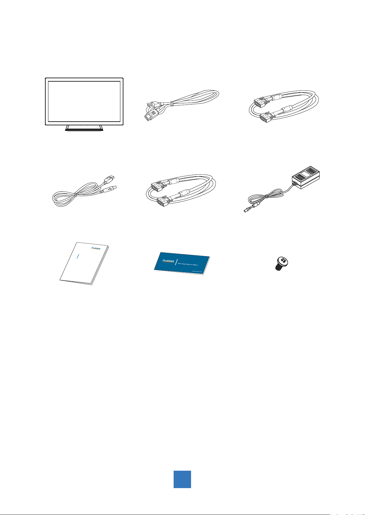
LCD Display Power Cord VGA Signal Cable
USB Cable ( A to B)
xxxxxxxxx
/
xxxxxxxxx
xxxxxxxxx
USER’S GUIDE
www.planartouch.com
DVI-D Cable
Landing StripUser’s Guide
DC Power Supply
Cable Cover Screw
3
Page 7
Installation
Product Overview
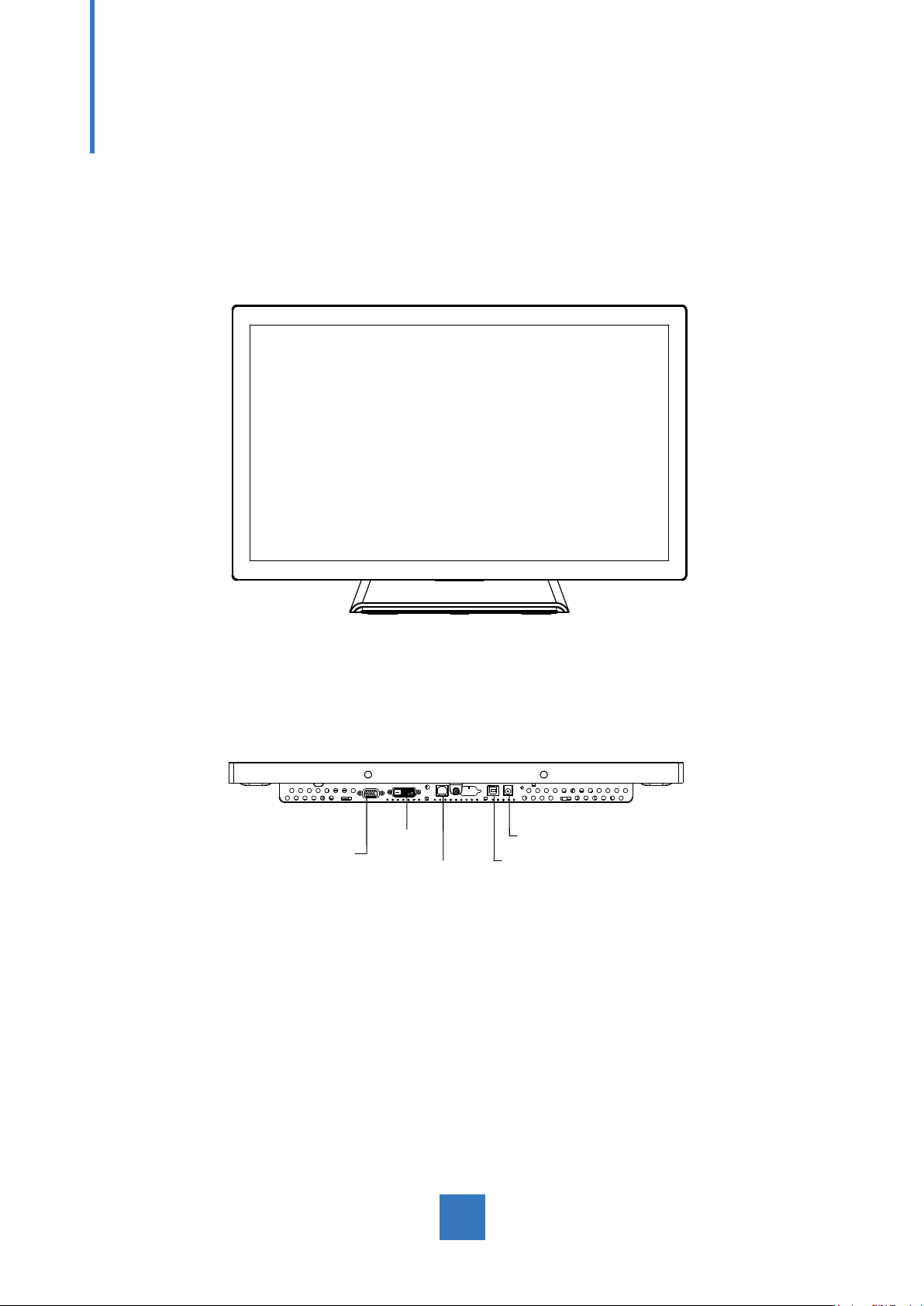
• Front View
• Bottom View (Without Stand)
VGA
DVI
RJ-Type
DC IN
USB
4
Page 8
VESA Mount for Your Monitor
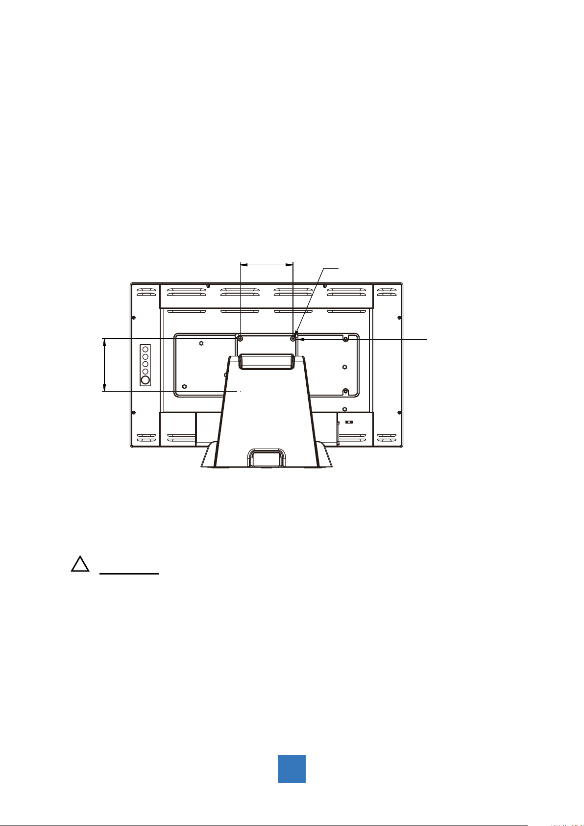
This monitor conforms to the VESA Flat Panel Mounting Physical Mounting Interface
standard which denes a physical mounting interface for at panel monitors, and
corresponding with the standards of at panel monitor mounting devices, such as wall and
table arms. The VESA mounting interface is located on the back of your monitor.
To mount the monitor on a UL certied swing arm or other mounting xture, follow the
instructions included with the mounting xture to be used.
100.0 mm
100.0 mm
Slots(X6)
VESA
Mounting
Interface
!
Warning!
Please select the proper screws!
The distance between the back cover surface and the bottom of the screw hole
is 8 mm. Please use four M4 screws diameter with proper length to mount your
monitor.
Please note: the mounting stand must be able to support at least 17.6 lbs (8Kg).
5
Page 9
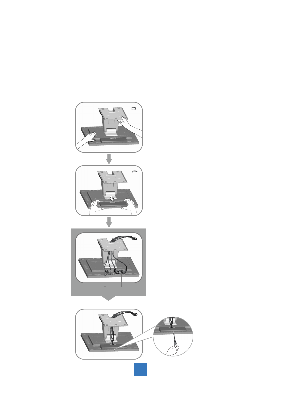
Step 3
VGA
USB DVI
DC IN
Step 2Step 1
Step 2
Step 2Step 4
Start Your Installation
Please follow these instructions so that you can hook up the cables to associated connectors.
1. Lay the display at on an even surface.
2. Move the stand into position as seen in the step 1 diagram.
3. Remove the cable cover as seen in the step 2 diagram.
4. Connect the cables to the appropriate connectors as seen in the step 3 diagram.
5. Re-attach the cable cover. Take the screw (CBM M3x6) out of the accessory box, and
insert the screw into the cable cover and monitor as seen in the step 4 diagram.
6
Page 10

Connecting the Display (Figure 8.1)
To setup this display, please refer to the following gure and procedures.
1. Be sure all equipment is turned off.
2. Connect the DC plug to the power connector on the monitor and the other end into an
electrical outlet (8.1).
3. Connect the D-SUB or DVI cable from the display’s D-SUB or DVI input connector to the
D-SUB or DVI connector of your host computer and tighten the screws (8.1).
4. Connect the USB cable from the USB port of your display to the USB port (8.1) of your
computer.
5. Congure the touch screen. Refer to the “Touch Screen Driver Installation” section on
page 17.
6. Once the touch screen is congured, the monitor is ready for use.
!
Notice!
To ensure the display works well with your computer, please congure the display
mode of your graphics card to make it less than or equal to 1920 x 1080 resolution
and make sure the timing of the display mode is compatible with the LCD display.
We have listed the compatible “Video Modes” of your LCD display in the appendix
(on page 16) for your reference.
Applicable external power supply: Lite-On/PA-1051-0
7
Page 11
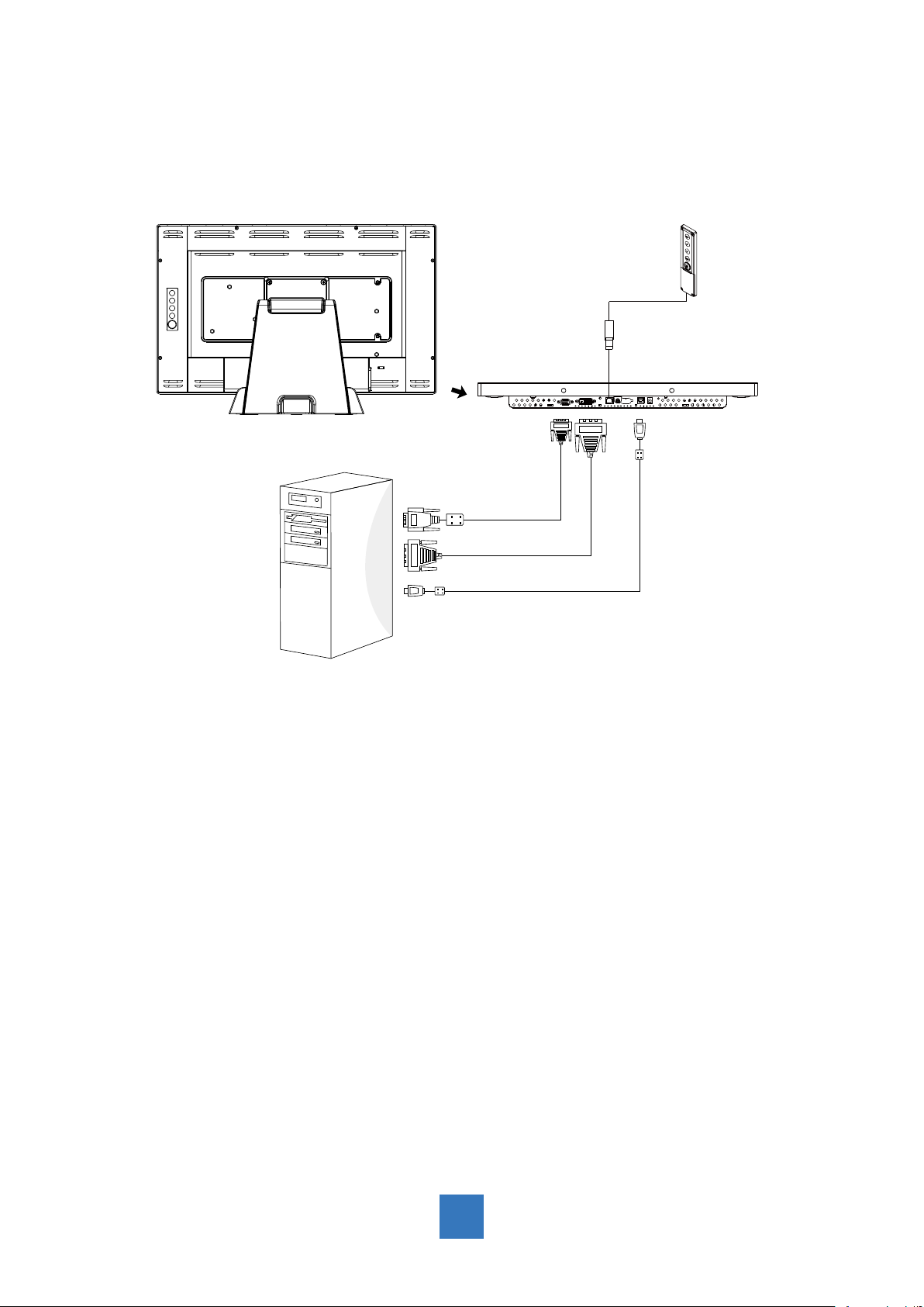
(Figure 8.1)
(Optional)
8
Page 12
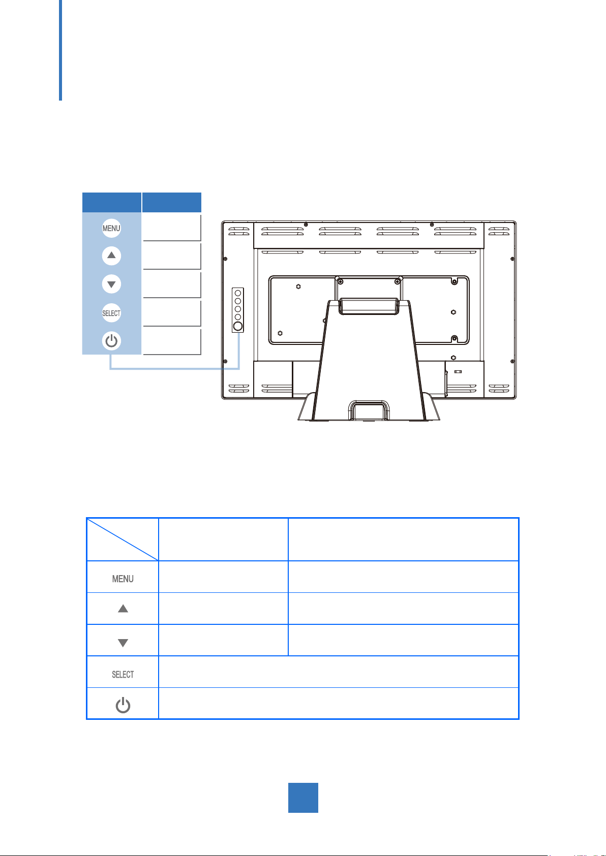
User Controls
Side Panel Controls
Icon Key Name
Menu
Up
Down
Select
Power
OSD
Key
Menu off status Menu on status
Menu appear Menu disappear / return to main item
Brightness Main item select up / Adjust up
Contrast Main item select down / Adjust down
Select sub-item function
Power On / Off
9
Page 13

How to Use the OSD Menus
Icon Key Name
1. Press the “Menu” button to pop up the “on-screen menu” and press “Up” or “Down”
button to select among the ve functions in the main menu.
2. Choose the adjustment items by pressing the “Select” button.
3. Adjust the value of the adjustment items by pressing the “Up” or “Down” button.
4. With the OSD menu on the screen, press the “Menu” button to return to the main menu
or to exit OSD.
5. The OSD menu will automatically close, if you have left it idle for a pre-set time.
6. To Lock the OSD / Power menu buttons, please follow the instructions below.
(Please note: the monitor has to be turned ON with a valid signal pre-set)
(a.) Press the “Menu” key; the OSD menu will open.
(b.) Press and hold the “Menu” key again with the OSD menu on the screen; the OSD
menu will disappear. Then press the “Power” key 1 time while the menu key is still
being pressed. The “Lock/Unlock” menu will appear for 3 seconds.
(c.) Use the “Select” key to select OSD or Power setting then set at “Lock” by pushing the
“UP” or “Down” button.
(d.) When the “UP” or “Down” button is released, the previous setting will be saved and
exit the “Lock/Unlock” menu automatically.
7. To Unlock the OSD / Power menu buttons, please follow the instructions below.
(Please note: the monitor has to be turned ON with a valid signal pre-set)
(a.) Press and hold the “Menu” key then press the “Power” key simultaneously; the
“Lock/Unlock” menu will appear for 3 seconds.
(b.) Use the “Select” key to select OSD or Power setting then set at “Unlock” by pushing
the “UP” or “Down” button.
(c.) When the “Up” or “Down” button is released, the previous setting will be saved, and
the “Lock/Unlock” menu will close automatically.
Please note:
a. When the OSD Lock function is selected, this indicates that all the buttons except
the “power” button are now disabled.
b. When the Power Lock function is selected, the “Power” key is disabled. The user
cannot turn off the monitor with the “Power” key.
Menu
Up
Down
Select
Power
10
Page 14

On-Screen Display Menus
Main OSD Menu:
ITEM CONTENT
Contrast The monitor luminance level control.
Brightness The monitor backlight level control.
Auto Adjust Fine-tune the image to full screen automatically.
Left/Right Moving screen image horizontal position to left or right.
Up/Down Moving screen image vertical position to up or down.
Horizontal size The screen image horizontal dot clock adjustment.
Fine The screen image pixel phase adjustment.
OSD Left/Right Moving OSD menu horizontal position to left or right.
OSD Up/Down Moving OSD menu vertical position to up or down.
OSD Time out OSD auto-disappear time selection.
OSD Language
Factory Reset Factory default value restored.
RGB Color temperature selection. (9300K, 6500K, 5500K, 7500K, User)
OSD menu language selection. ( English, French, Japanese, Deutsch,
Spanish, Italian, Traditional Chinese and Simplied Chinese)
11
Page 15

Appendix
Troubleshooting
If you are experiencing trouble with the display, refer to the following. If the problem persists,
please contact your local dealer or our service center.
Problem: No image appears on screen.
► Check that all the I/O and power connectors are correctly and well connected
as described in the “Installation” section.
► Make sure the pins of the connectors are not crooked or broken.
Problem: Partial Image or incorrectly displayed image.
► Check to see if the resolution of your computer is higher than that of the display.
► Recongure the resolution of your computer to make it less than or equal to
1920 x 1080.
Problem: Image has vertical ickering line bars.
► Use “Horizontal size” to make an adjustment.
► Check and recongure the display mode of the vertical refresh rate of your
graphic card to make it compatible with the display.
Problem: Image is unstable and ickering
► Use “Fine” to make an adjustment.
Problem: Image is scrolling
► Check and make sure the VGA signal cable (or adapter) is securely connected.
► Check and recongure the display mode of the vertical refresh rate of your
graphics card to make it compatible with the display.
Problem: Vague image (characters and graphics)
► Use “Horizontal size” to make an adjustment. If this problem still exists, use “Fine”
to make an adjustment.
12
Page 16

Warning Signal
If you see warning messages on your screen, this means that the display cannot receive a
clean signal from the computer graphics card.
Below are the three kinds of Warning Signal. Please check the cable connections or contact
your local dealer or our service center for more information.
No Signal
This message means that the display has been powered on but it cannot receive any signal
from the computer graphics card. Check all the power switches, power cables, and VGA/DVI
signal cable.
Going to Sleep
The display is under the power saving mode. In addition, the display will enter power saving
mode when experiencing a sudden signal disconnecting problem.
The monitor can be activated by pressing any keyboard, triggering the mouse or touching
the screen.
Out of Range
This message means that the signal of the computer graphic card is not compatible with
the display. When the signal is not included in the “Video Modes” list we have listed in the
Appendices of this manual, the monitor will display this message.
13
Page 17
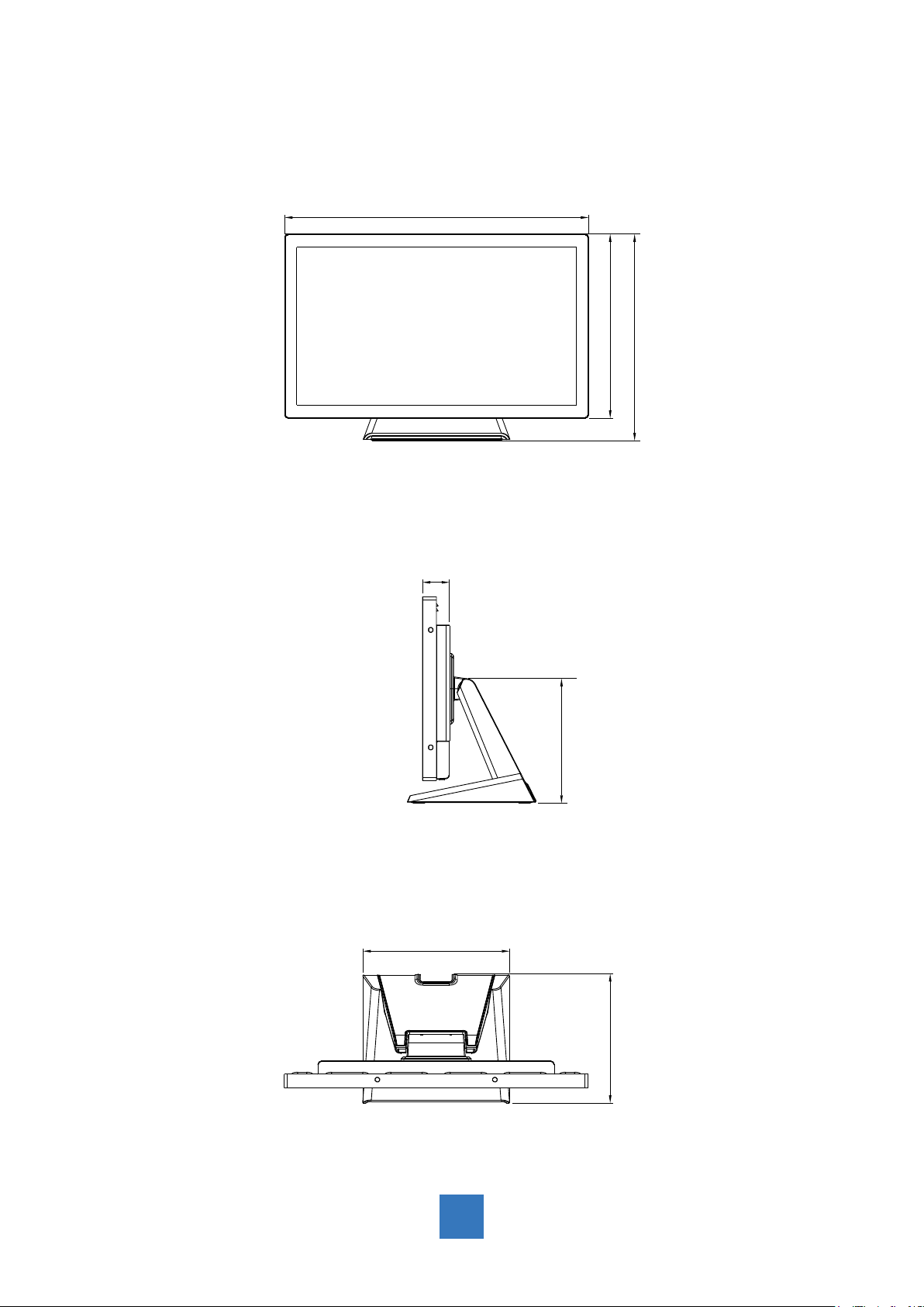
Product Dimensions
► Side View
► Front View
► Top View
517.4 mm
313.3 mm
351.7 mm
249.6 mm
219.0 mm
212.0 mm
46.0 mm
14
Page 18
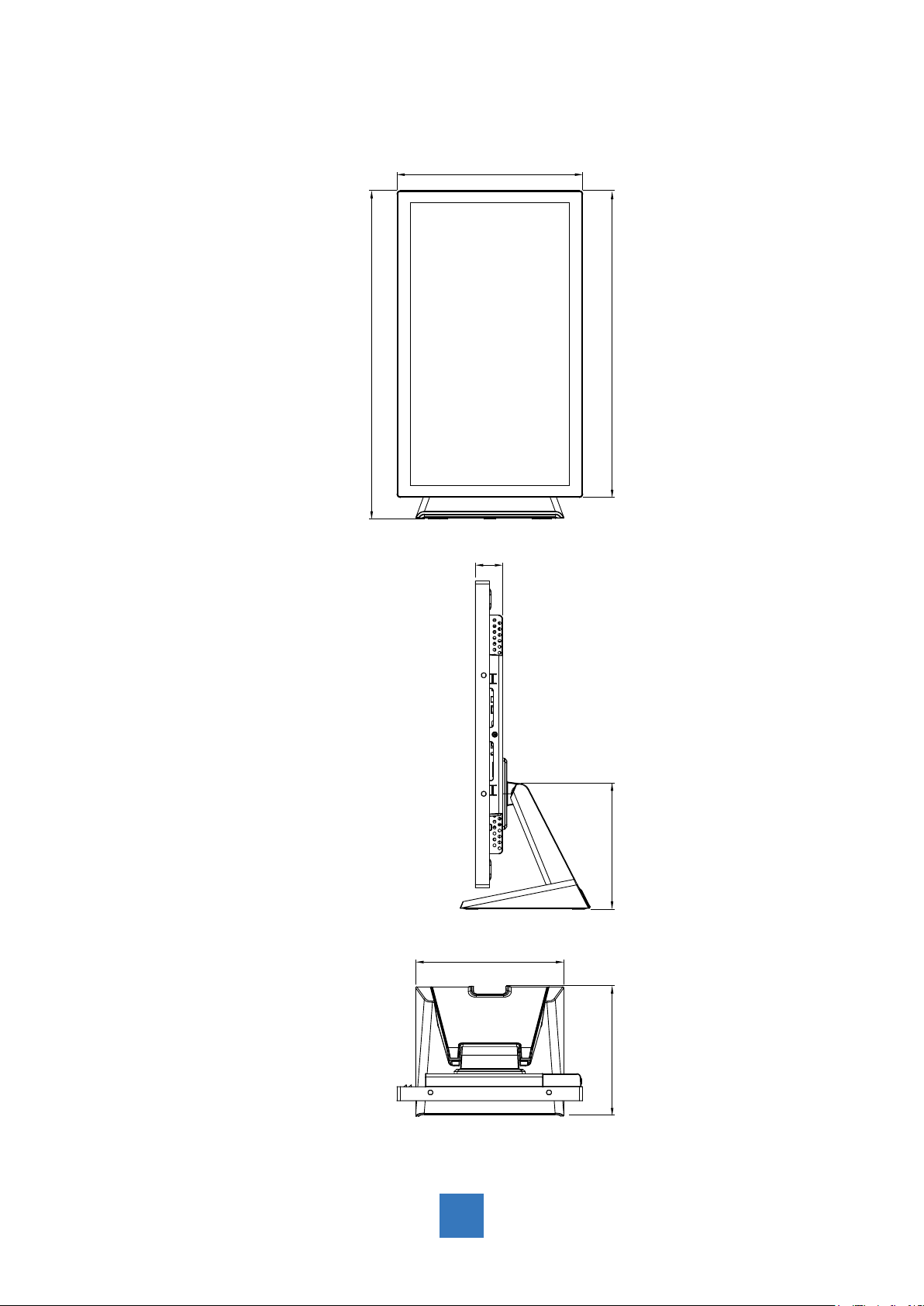
Rotate
► Front View
313.3 mm
► Side View
553.7 mm
517.4 mm
46.0 mm
► Top View
212.0 mm
249.6 mm
219.0 mm
15
Page 19

Compatibility Modes
Mode Resolution H-Frequency(khz) V-Frequency(hz)
IBM VGA 720X400 31.47 70
IBM VGA 640X480 31.47 60
Apple MacII 640X480 35.00 66
VESA VGA
VESA VGA 640X480 37.50 75
VESA SVGA
VESA SVGA 800X600 37.88 60
VESA SVGA 800X600 48.08 72
VESA SVGA 800X600 46.88 75
Apple Mac 832X624 49.72 75
VESA XGA 1024X768 48.36 60
VESA XGA 1024X768 56.48 70
VESA XGA 1024X768 60.02 75
VESA SXGA 1280X1024 64.00 60
VESA SXGA 1280X1024 80.00 75
640X480
800X600
37.86
35.16
72
56
VESA SXGA 1152X864 67.50 75
VESA SXGA 1280X960 60.00 60
WXGA+ 1440X900 56.00 60
WXGA+ 1440X900 70.60 75
WSXGA+ 1680X1050 65.20 60
WSXGA+ 1680X1050 (VGA only) 82.30 75
VESA WXGA 1280X768 47.776 60
WSXGA+ 1920X1080 67.50 60
16
Page 20

Touch Screen Driver Installation
The is available with USB connection. The touch driver is available at www.planar.com/sup-
port for these operating systems: Windows® 7/8, VISTA, XP, 2000, CE,
XP Embedded, Linux kernel 2.6.x (32 bit & 64 bit), Apple® Mac OS. (Windows 7/8 Multi
touch without driver)
Please Note:
1. The PT2245PW is Microsoft® Windows® HID (Human Interface Device)
compatible if you use the USB touch screen interface. No additional software driver is
required for general operation of the touch screen. A calibration tool can be installed for
improved touch position accuracy. See “Optional Calibration Tool Install” section for more
information.
2. For PT2245PW, the system requires 15 seconds for Windows 7/8 to process the touch
program while turning power on/off or plugging/unplugging USB cable.
17
Page 21

PT2245PW Calibration Instruction:
Calibrating the touch screen in Windows 7/8:
1. Tap the Start button, Control Panel and then Hardware and Sound.
2. Under Tablet PC Settings, tap Calibrate the screen for pen or touch input.
3. On the Display tab, under Display options, tap Calibrate and then Yes to allow the
program to make changes.
4. Follow the on-screen instructions to calibrate the touch screen.
18
Page 22

19
Page 23

PT2245PW Install Instruction:
If you are using a PC running, Windows® 7/8, VISTA, XP, 2000, follow the
instructions below:
1. Power on the PC.
2. Make sure that the USB cable is connected to the computer.
3. Visit www.planar.com/support.
4. Follow the step-by-step instructions as shown on the pop-up windows.
If you are using a PC running driver Linux kernel 2.6.x (32 bit & 64 bit),
follow the instructions below:
1. Power on the PC.
2. Make sure that the USB cable is connected to the computer.
3. Visit www.planar.com/support.
4. Follow the step-by-step instructions as shown on the pop-up windows.
If you are using a PC running Windows® XP Embedded, follow the
instructions below:
Express:
1. Power on the computer.
2. Make sure that the USB cable is connected to the computer.
3. Be sure that your EWF is disabled. If your EWF is enabled, please disable the EWF by
using the EWF Manager command.
4. Once the EWF is disabled click on the XP driver at www.planar.com/support. and follow
the step-by-step instructions as shown on the pop-up windows.
Custom:
1. Power on the computer.
2. Make sure that the USB cable is connected to the computer.
3. Follow the step-by-step instructions found in the zipped le at www.planar.com/support.
If you are using a PC running Windows® CE, follow the instructions
below:
1. Power on the computer.
2. Make sure that the USB cable is connected to the computer.
3. Using Platform Builder, build an image le by following the step-by-step instructions
found in the zipped le at www.planar.com/support.
If you are using a PC running Linux or Apple® Mac OS, follow the
instructions below:
1. Power on the computer.
2. Make sure that the USB cable is connected to the computer.
3. Follow the step-by-step instructions found in the zipped le at www.planar.com/support.
20
Page 24

Technical Support
Cables and Accessories
To nd cables and accessories for your Planar monitor, touch screen or other Planar products
visit our online store at www.PlanarOnline.com.
Technical Support
Visit Planar at http://www.planar.com/support for operations manuals, touchscreen drivers,
warranty information and access to Planar’s Technical Library for online trouble shooting.
To speak with Planar Customer Support please have you model and serial number available
and dial:
Planar Support
Tel: 1-866-PLANAR1 (866-752-6271) or +1 503-748-5799 outside the US.
Hours: 24 hours a day, 7 days a week.
Toll or long distance charges may apply.
21
Page 25

Planar Systems, Inc.
Customer Service
24x7 Online Technical Support: http://www.planar.com/support
1195 NW Compton Drive
Beaverton, OR 97006-1992
Tel: 1-866-PLANAR1 (866-752-6271) or +1 503-748-5799 outside the United States.
Hours: 24 hours a day, 7 days a week
© 2013 Planar Systems, Inc. 10/13 Planar is a registered trademark of Planar Systems, Inc.
Other brands and names are the property of their respective owners.
Technical information in this document is subject to change without notice.
020-1224-00B
820400300102
 Loading...