

Page 1

PT1710MX
Touchscreen LCD Monitors
USER’S GUIDE
www.planar.com
Page 2

Page 3
Important Recycle Instructions:
Lamp(s) inside this product contain mercury. This product may
contain other electronic waste that can be hazardous if not disposed of
properly. Recycle or dispose in accordance with local, state, or federal Laws.
For more information, contact the Electronic Industries Alliance at
WWW.EIAE.ORG. For lamp specific disposal information check
WWW.LAMPRECYCLE.ORG.
Page 4

Page 5

1
Table of Contents
Usage Notice
Precautions ........................................................................................ 2
Introduction
About Planar’s PT1710MX.. ............................................................... 3
Touch Screen for PT1710MX……………………………………………..4
Package Overview ............................................................................. 5
Installation
Product Overview ............................................................................... 6
VESA Mount for your Monitor…………………………………………….9
Start Your Installation…………………………………………………….10
Connecting the Display………………………………..…………………11
User Controls
Front Panel Controls ........................................................................ 13
How to Use the OSD Menus ............................................................ 14
On-Screen Display Menus ............................................................... 15
Appendix
Troubleshooting ............................................................................... 16
Warning Signal ................................................................................. 17
Product Dimensions ......................................................................... 18
Compatibility Modes ......................................................................... 19
Touch Screen Driver Installation………………………………………..20
Product Registration and Technical Support…………………………..23
Page 6

2
Usage Notice
Warning
Warning
Precautions
Follow all warnings, precautions and maintenance as recommended
in this user’s manual to maximize the life of your unit.
Do:
Don’t:
- To prevent the risk of fire or shock hazards, do not
expose this product to rain or moisture.
- Please do not open or disassemble the product as
this may cause electric shock.
Turn off the product before cleaning.
Touch screen surface may be cleaned using a soft clean cloth
moistened with mild window glass commercial cleaners or 50/50
mixture of water and isopropyl alcohol.
Use a soft cloth moistened with mild detergent to clean the display
housing.
Use only high quality and safety approved AC/DC adapter that
comes with your monitor.
Disconnect the power plug from AC outlet if the product is not going
to be used for an extended period of time.
Do not touch the LCD Display screen surface with sharp or hard
objects.
Do not use abrasive cleaners, waxes or solvents for your cleaning.
Do not operate the product under the following conditions:
- Extremely hot, cold or humid environment.
- Areas susceptible to excessive dust and dirt.
- Near any appliance generating a strong magnetic field.
- In direct sunlight.
Page 7

3
Introduction
About Planar’s PT1710MX
The PT1710MX is a 17” flat panel screen with an active matrix,
thin-film transistor (TFT) liquid crystal display (LCD).
Features include:
Direct Analog signal input
Active matrix TFT LCD technology
1280x1024 SXGA resolution
17” viewable display area
31.5 ~ 80 kHz horizontal scan
56 ~ 75 Hz high refresh rate
0.264mm x 0.264mm Pixel pitch
Auto adjustment function
Multilingual OSD user controls
VESA DPMS power saving
Kensington security slot
100 mm VESA mount
Removable base for flexible mounting solutions.
5-wire Resistive touch screen with dual RS-232 Serial/USB controller
Built-in Speakers-1W/channel.
Page 8

4
Touch Screen for PT1710MX
Analog 5-wire resistive touch screen for finger and stylus input
Surface: Anti-glare treatment
Interface: Dual RS-232 Serial/USB controller
Durability: 35 million touches at a single point
Hardness of surface: 2H MIN (As provided in JIS K5400)
Operating force: 0.10~1.96N(10g~200g when using a silicon tipped pen
with a 3 mm radius and a hardness of 60)
Transmittance: 76% (Typ.)
Driver: Supports Microsoft Windows® VISTA, XP, 2000, ME, 98, NT4.0,
CE, XP Embedded, Linux, Apple® Mac OS
Page 9
5
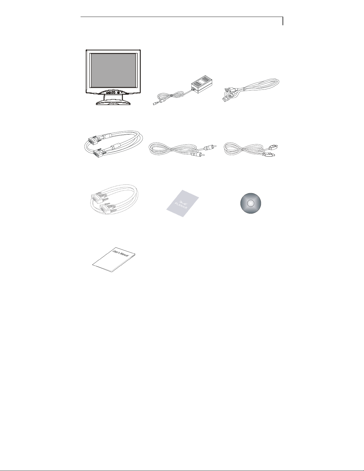
Package Overview
LCD Display Power Adapter Power Cord
VGA Signal Cable Audio-in Cable USB Cable
RS-232 Cable Landing Strip Touchscreen Driver
User’s Guide
Installation CD-ROM
Page 10

6
Installation
Product Overview
Front View
Back View
Page 11
7
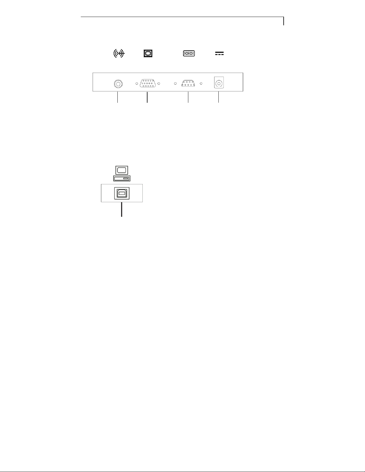
Connector Ports “A”
Audio
input
Connector Ports “B”
USB
VGA
input
RS-232
input
DC
Power-in
Page 12

8
Kensington Security Slot
The monitor can be secured to your desk or any other fixed object with
Kensington lock security products. The Kensington lock is not included.
Page 13

9
VESA Mount Your Monitor
This monitor conforms to the VESA Flat Panel Mounting Physical Mounting
Interface Standard which defines a physical mounting interface for flat panel
monitors, and corresponding standards for flat panel monitor mounting
devices, such as wall and table arms. The VESA mounting interface is
located on the back of your monitor.
To mount the monitor on a swing arm or other mounting fixture, follow the
instructions included with the mounting fixture to be used.
Warning!
Please select the proper screws!
The distance between the back cover surface and the bottom of the
screw hole is 8mm. Please use M4 screw diameter with a maximum
length of 8 mm.
Page 14

10
Start Your Installation
Remove the Back Cover
Please follow these instructions to remove the cover on the back panel of
the LCD so that you can connect the cables in “Connector Ports A.”
1. To remove the back cover, follow the arrows in Figure A and press with
both your thumbs. The cover should be removed by pressing firmly
along the edges while pulling on the cover.
2. Follow the instructions on P. 11 ( Figure 11.1 ) to connect the cables in
“Connector Ports A.”
3. Fix the cover back to the LCD by pressing firmly until the tabs snap into
place. You may also keep the cables in order by using the cable
organizer.
Page 15

11
Connecting the Display (Figure 11.1)
To setup this display, please refer to the following figure and procedures.
1. Be sure all equipment is turned off.
2. Connect the DC power cord to the power connector on the monitor; plug
one end of the AC power cord into the power adapter, and the other end
into an electrical outlet (11.1).
3. Connect the VGA signal cable from the display’s VGA input connector to
the 15-pin connector of your host computer and tighten the screws
(11.1).
4. Connect the Audio-In cable from the audio input port of your display to
the Audio-out port of your computer (11.1).
5. Configure the touch screen. Refer to the “Touch Screen Driver
Installation section on page 20.
6. Once the touch screen is configured, the monitor is ready for use.
To ensure the LCD display works well with your computer, please
configure the display mode of your graphics card to make it less
than or equal to 1280 x1024 resolution and make sure the timing
of the display mode is compatible with the LCD display.
We have listed the compatible “Video Modes” of your LCD display
in the appendix for your reference.
Page 16

12
Figure 11.1
Page 17

13
User Controls
Decreases the brightness of the display
Increases the brightness of the display
power of the LCD
Amber indicates the display is in
Front Panel Controls
No / Icon
MENU
SELECT/AUTO
Control Function
Menu button Display the OSD menus
Select – To select the adjustment items from
Select/Auto
Brightness
Minus/Minus
Brightness
Plus/Plus
Power Switch
Power LED
OSD menus.
Auto – To activate the “Auto Adjustment”
function to obtain an optimum image.
1.
image.
2. Decreases value of the adjustment items.
1.
image.
2. Increases value of the adjustment items.
Switches on/off the
display.
1. Green indicates the display is turned on.
2.
power-saving mode.
Page 18

14
How to Use the OSD Menus
1.
Press the "MENU" button to pop up the “on-screen menu” and to select
among the four Main Menus.
2. Choose the adjustment items by pressing the “Select/Auto” button.
3. Adjust the value of the adjustment items by pressing the “”or ““ button.
4. The OSD menu will automatically close, if you have left it idle for a
pre-set time.
5. To disable the OSD menu buttons, please follow the instructions below:
(Please note: the monitor has to be ON with a valid signal preset)
a. Press and hold the “-“ and “Menu” key simultaneously for 4 seconds.
b. The wording “OSD Locked” will appear for 4 seconds on the monitor.
This indicates that all the front buttons, with the exception of the
power button, are now disabled.
6. To enable the OSD menu buttons, please follow the instructions below.
(Please note: the monitor has to be ON with a valid signal present.)
a. Press and hold the “-“ and “Menu” key simultaneously for 4 seconds.
b. The wording “OSD Unlocked” will appear for 4 seconds on the
monitor. This indicates that all the front buttons are now enabled.
Page 19

15
MAIN ME
NU SUB MENU
Function Description
Remark
On-Screen Display Menus
Main OSD Menu:
Auto-Adjustm ent
Contrast
Brightness
Horizontal Position
Vertical Position
Clock
Phase
Display Mode
OSD Off-Time
Languag e English /
Sharpness
Reset
No/Yes
0-100
0-100
0-100
0-100
0-100
0-63
ADJ
5-60
Francais
Deutsch /
Espanol
Italiano /
Japanese
1-4
No/Yes
Choose this function to obtain an optimum
image.
Adjust the contrast of the display image.
Adjusts the brightness of the image.
Changes the horizontal position of the image.
Changes the vertical position of the image.
Changes the display data frequency to match
the frequency of your graphic card. When you
are experiencing vertical flickering bar,
this function to make an adjustment.
Synchronizes the signal timing of the display
to that of the graphic card. When you are
experiencing vertical flickering image, use
this function to make an adjustment.
Select this function to view the display
resolution, vertical refresh, and horizontal
scan of the current mode.
Adjusts the time period for OSD menu to
disappear.
Choose the language you need.
Adjust the sharpness of the image. Default 3
Returns the display parameters of the current
mode to its factory default settings.
Default
Default 50
Default 70
Default 50
Default 50
Default 50
use
Default 30
English
Volume
Mute
Color Setting
Color
Adjustment-Red
Color
Adjust me nt-Green
Color
Adjustment-Blue
9300K /
0-32
No/Yes
6500K
Preset /
Custom
0-100
0-100
0-100
Controls the sound volume. Default 20
Disables the sound immediately.
Adjusts the color temperature.
It allows you to adjust the red color of the display
It allows you to adjust the green color of the
display.
It allows you to adjust the blue color of the display
Default Preset
. Default 100
Default 100
. Default 100
Page 20

16
Appendix
Troubleshooting
If you are experiencing trouble with the LCD display, refer to the following. If
the problem persists, please contact your local dealer or our service center.
Problem: No image appears on screen.
Check that all the I/O and power connectors are correctly and well
connected as described in the “Installation” section.
Make sure the pins of the connectors are not crooked or broken.
Problem: Partial Image or incorrectly displayed image.
Check to see if the resolution of your computer is higher than that of the
LCD display.
Reconfigure the resolution of your computer to make it less than or equal
to 1280 x 1024.
Problem: Image has vertical flickering line bars.
Use "Clock" to make an adjustment.
Check and reconfigure the display mode of the vertical refresh rate of your
graphic card to make it compatible with the LCD display.
Problem: Image is unstable and flickering
Use "Phase" to make an adjustment.
Problem: Image is scrolling
Check and make sure the VGA signal cable (or adapter) is securely
connected.
Check and reconfigure the display mode of the vertical refresh rate of your
graphics card to make it compatible with the LCD Display.
Problem: Vague image (characters and graphics)
Use "Clock" to make an adjustment. If this problem still exists, use “Phase”
to make an adjustment.
Page 21

17
Warning Signal
If you see warning messages on your LCD screen, this means that
the LCD display cannot receive a clean signal from the computer
graphics card.
There may be two sources for this problem. Please check the cable
connections or contact Planar for more information.
No Signal
This message means that the LCD Display has been powered on but it
cannot receive any signal from the computer graphics card. Check all the
power switches, power cables, and VGA signal cable.
Out of Range
This message means that the signal of the computer graphic card is not
compatible with the LCD display. When the signal is not included in the
“Video Modes” list we have listed in the Appendices of this manual, the
LCD display will display this message.
Page 22

18
Product Dimensions
Page 23

19
V. Frequency
(Hz)
H. Freq
uency
(kHz)
Compatibility Modes
Mode Resolution
IBM VGA 640 x 350 70 31.5
IBM VGA
IBM VGA
VESA VGA 640 x 480 72 37.9
VESA VGA 640 x 480 75 37.5
VESA SVGA 800 x 600 56 35.2
VESA SVGA
VESA SVGA
VESA SVGA
VESA XGA 1024 x 768 60 48.4
VESA XGA
VESA XGA
VESA SXGA 1280X1024
VESA SXGA 1280X1024
Apple Mac II 640 x 480 67 35.0
Apple Mac
Apple Mac
720 x 400 70
640 x 480 60
800 x 600
800 x 600
800 x 600
1024 x 768
1024 x 768
832 x 624 75 49.7
1024 x 768 75 60.2
60 37.9
72 48.1
75 46.9
70 56.5
75 60.0
60 64.0
75 80.0
31.5
31.5
Page 24

20
Touch Screen Driver Installation
The PT1710MX is available with both RS-232 and USB connections. The
PT1710MX is Microsoft® Windows® HID (Human Interface Device)
compatible if you use the USB touch screen interface. No additional
software driver is required for general operation of the touch screen. A
calibration tool can be installed for improved touch position accuracy. See
“Optional Resistive Calibration Tool Install” section for more information.
The touch driver is located on the enclosed CD-ROM for these operating
systems: Windows® VISTA, XP, 2000, ME, 98, NT4.0, CE,
XP Embedded, Linux, Apple® Mac OS
Please note: Do not plug in both RS232 and USB cables. Doing so may
cause a driver conflict, making your touch screen idle.
Driver Installation Process:
1. Before you start to install the touch driver, please be sure the USB or the
RS-232 Serial cable is connected to the PC and LCD display.
2. Uninstall any touch screen driver that may be on your system.
3. Restart your computer.
4. Click on the appropriate link found on the CD-ROM.
5. Follow instructions as found below.
6. After installation is complete, click “Finish” to complete installation.
Page 25

21
PT1710MX Optional Resistive Calibration Tool Install:
If you would like to use the Optional Resistive Calibration Tool, follow the
instructions below:
1. Open the CD-Rom.
2. Select the Monitor Size and then Model Name
3. Click on the “Load Utility” button that appears to the right of the
Model Name.
4. The HID calibration tool will automatically open. From here the user
can choose to do the following:
a. 4 Points Calibration
b. 9 Points Linearization
c. 25 Points Linearization
d. Clear
e. Draw Test
f. Advanced. In the Advanced settings area the user may do
the following:
i. Adjust the Double Click Area
ii. Enable auto right click and adjust the auto right click
time
iii.
Choose to be either in the HID Mouse Mode or HID
Digitizer Mode (Windows® Vista only)
iv. Simply click the “Apply” button once the settings are
finalized.
Page 26

22
If you are using a PC running Windows® Vista, XP or 2000 operating system,
follow the instructions below.
Using the RS232 connection:
1. Be sure that RS232 cable is connected from the computer.
2. Power on the computer.
3. Load the touch screen driver CD.
4. Follow the step-by-step instructions as shown on pop-up windows.
Using the USB connection:
1. Be sure that USB cable is connected from the computer.
2. Power on the computer.
3. Load the touch screen driver CD.
4. Follow the step-by-step instructions as shown on pop-up windows.
If you are using a PC running Windows® XP Embedded, follow the
instructions below:
1. Power on the computer.
2. Make sure that the RS232 or USB cable is connected to the computer.
3. Be sure that your EWF (Enhanced Write Filter) is disabled. If your EWF
is enabled, please disable the EWF by using the EWF Manager
command.
4. Once the EWF is disabled click on the XP driver on the CD and follow the
step-by-step instructions as shown on the pop-up windows.
Page 27

23
Product Registration and Technical Support
Register Your Planar Products Today
Thank you for choosing Planar. To assure you receive all the benefits of your
Planar product and services, register your Planar product today. Visit our website
at http://www.planar.com/support/product_registration.html.
Cables, Replacement Lamps, Accessories
To find cables, replacement lamps and accessories for your Planar projector,
LCD monitor, touch screen or other Planar products visit our online store at
www.PlanarOnline.com or find other stores who carry Planar products at
http://www.planar.com/howtobuy.
Technical Support
Visit Planar at http://www.planar.com/support for product registration,
operations manuals, touch screen drivers, warranty information and access to
Planar’s Technical Library for online troubleshooting.
Online chat service is available Monday through Friday from 12am to 6pm
Pacific Time.
To speak with Planar Customer Support please have you model and serial
number available and dial:
Planar Support
Tel: 1-866-PLANAR1 (866-752-6271) or +1 503-748-5799 outside the US.
Hours: 24 hours a day, 7 days a week.
Toll or long distance charges may apply.
Page 28

Page 29

PT1710MX
触摸屏液晶显示器
用户指南
www.planar.com
Page 30

本文档中包含的信息如有变更,恕不另行通知。
本文档包含由版权保护的专属信息。保留所有权利。未经事先书面许可,不得
复制、翻译本文档的内容或将其存储在检索系统中,或者以任何形式(电子、
机械、影印、记录或其它方式)进行传输。
Windows 是 Microsoft, Inc.
其它品牌或产品名称均属各自拥有人所有。
重要资源回收说明:
的注册商标。
本产品内的灯泡含有汞元素。 本产品可能包含其它电子废弃有
害物质,如果处理不当,则会造成危害。请按照当地、州省或联邦法
律进行特殊废弃物回收处理。有关详情,请联系电子工业联盟:
WWW.EIAE.ORG
。有关灯泡的具体处理信息,请查阅
WWW.LAMPRECYCLE.ORG。
Page 31

目录
使用须知
使用须知
使用须知使用须知
1
使用前注意事项
介绍
介绍
介绍介绍
Planar PT1710MX
PT1710MX
组件概览
安装
安装
安装安装
产品概述
显示器的
开始安装
连接显示器
用户控制
用户控制
用户控制用户控制
前面板控制
如何使用
...................................................................................... 5
...................................................................................... 6
VESA
.................................................................................... 10
OSD
............................................................................ 2
的触摸屏
安装
................................................................................. 11
................................................................................. 13
菜单
简介
............................................................... 3
................................................................... 4
.................................................................. 9
.................................................................. 14
屏幕显示菜单
附录
附录
附录附录
故障排除
警告信号
................................................................................... 16
................................................................................... 17
............................................................................. 15
Page 32

2
产品尺寸
兼容性模式
触摸屏驱动程序安装
产品注册和技术支持
.................................................................................... 18
................................................................................. 19
................................................................... 20
................................................................... 23
Page 33

使用须知
警告
警告
-
警告警告
使用前
使用前注意事项
使用前使用前
遵照本用户手册中建议的所有警告、注意事项和维护步骤,以延
长产品的寿命。
应做:
应做:
应做:应做:
为了避免火灾或者触电危险,请勿使本产品遭受
雨淋或受潮。
警告
警告
-
警告警告
请勿打开或拆解本产品,以免遭到电击。
注意事项
注意事项注意事项
清洁之前关闭设备。
可以使用干净软布,沾取适度窗户玻璃清洁剂或水与异丙醇
50/50
混合物,清洁触摸屏。
使用沾有适度清洁剂的软布清洁显示器外壳。
只使用随显示器附带的高质量、经过安全认证的交流/直流适配
器。
如果长时间不使用设备,请从
以延长使用寿命。
AC
电源插座上拔下电源插头加
3
禁止
禁止::::
禁止禁止
禁止
禁止
用坚硬/尖锐物件接触
禁止禁止
禁止
禁止
使用研磨剂、蜡剂或溶剂进行清洁。
禁止禁止
禁止
禁止
在以下条件下使用设备:
禁止禁止
- 高温、严寒或非常潮湿的环境。
- 容易染尘沾污的环境。
LCD
显示屏表面。
Page 34

4
- 产生强磁场的电器的附近。
- 阳光直射。
Page 35

介绍
5
Planar PT1710MX简介
PT1710MX 17”
液晶显示屏(
功能特点:
直接模拟信号输入
有源矩阵
1280x1024 SXGA
17”
可视显示
31.5~80 kHz
56~75 Hz
0.264mm x 0.264mm
平板显示器采用有源矩阵、薄膜晶体管(
LCD
)。
TFT LCD
区域
水
平扫描
高
刷新频率
技术
分辨
简介
简介简介
率
像素点距
TFT
)
自
多语言
VESA DPMS
Kensington
100 mm VESA
可
动调整功
OSD
拆卸底
座,可
能
用户控制
节
能
防盗锁槽
安
装
实现灵活
的安
装解决方案
Page 36

6
5
线电阻
内
式触摸屏,配有
置扬声
器
–1W/声道
双
RS-232
串
行
/USB
控
制器
Page 37

7
PT1710MX触摸屏
模拟式5线电阻
表面:
接口:
耐久性:单点
表面硬度:
操纵力
200g
透射率
驱动程序:支持
XP Embedded, Linux, Apple® Mac OS
触摸屏
触摸屏触摸屏
防眩
光处理
双
RS-232
触摸
2H MIN(JIS K5400
:
0.10~1.96N
。)
:
76%
(
式触摸屏,可以用
串
行
/USB
3500
万次
(使用
典型
)
Windows® VISTA, XP, 2000, ME, 98, NT4.0, CE,
控
制器
3 mm
手指和光笔
上提供)
半径和60硬度的硅尖笔时
进行输入
10g
~
Page 38

组件概览
组件概览
组件概览组件概览
液晶
VGA
显示器
信号
线
8
电源适配器
电源
线
音频输入线
USB
线
RS-232线
快速入门卡
触摸屏
安装光
驱动程序
盘
用户
指南
Page 39

安装
LCD
显示器
面板控制
底座支架
扬声
器
产品概述
产品概述
产品概述产品概述
视图
9
后视图
Page 40

10
端口
B
端口 A(后盖内侧)
Page 41

端口
11
A
音频
输入
端口
B
USB
VGA
输入
RS-232
输入
DC
电源输入
Page 42

防盗锁槽
防盗锁槽防盗锁槽
防盗锁槽
可以用
Kensington
Kensington
防盗锁槽
防盗锁槽
防盗锁槽防盗锁槽
防盗锁
将显示器
12
固定到桌
子或其它
固定
物体上。
Kensington
防盗锁没
有随产品附带。
Ken
Kensi
KenKen
sing
ngtttton
sisi
ngng
on
onon
Page 43

显示器的
显示器的VESA安装
显示器的显示器的
安装
安装安装
13
本显示器符合
显示器的自行安
的相应标准。
若
要将显示器安
固定
物件附带的说明书。
VESA
安
装界
VESA
VESA
面
平板
显示器自行安
装界
面,以
及平板
安装接
口位于
装到活动臂杆
装界面标准,该标准定义了平板
显示器安装设备(如
显示器的
或其它安装治具上,请遵照要使用的安
背后
墙壁和桌台臂杆
。
插槽
)
装
警告
警告!!!!
警告警告
请选择正确的螺丝
请选择正确的螺丝!!!!
请选择正确的螺丝请选择正确的螺丝
Page 44

后盖表面与螺丝孔底部之间的距离为
后盖表面与螺丝孔底部之间的距离为
后盖表面与螺丝孔底部之间的距离为后盖表面与螺丝孔底部之间的距离为
请使用直径最长为
请使用直径最长为
请使用直径最长为请使用直径最长为
8 mm
的的的的M4螺丝。
螺丝。
螺丝。螺丝。
8 mm
。。。。
14
Page 45

开始安装
注意!
注意!注意!
注意!
开始安装
开始安装开始安装
拆卸后盖
15
请按照以下说明
到“端口A”。
1.
要
拆卸后盖
同时,沿着边缘用力
2.
按照11页(图
3.
用力按下,直
拆卸液晶
,请按照
到弹片卡扣入位,以便将后盖固定到
11.1
)的说明将
图A箭
按,即会卸下
显示器的
头所示,用
线缆连接到端口A。
后盖
后盖
双手拇指
。
,以便您可以将
按下。在
LCD
拉住后盖
。
您也
线缆连
可以使
接
的
用理
线槽依序排列线缆
。
包含有
理线槽
Page 46

您可以平放
您可以平放液晶
您可以平放您可以平放
整的表面上,以免刮碰造成
整的表面上,以免刮碰造成液晶
整的表面上,以免刮碰造成整的表面上,以免刮碰造成
液晶显示器
显示器,,,,以便它可以
液晶液晶
显示器显示器
以便它可以连接线缆。确保将它放在一个平
以便它可以以便它可以
液晶显示器
液晶液晶
连接线缆。确保将它放在一个平
连接线缆。确保将它放在一个平连接线缆。确保将它放在一个平
显示器损坏。
显示器显示器
损坏。
损坏。损坏。
16
Page 47

注意!
注意!注意!
注意!
连接显示器
连接显示器((((图图图图
连接显示器连接显示器
11.1
))))
17
要安装设置显示器,请参照下面的图示
1.
确
保所有设备已关闭。
2. 将DC
3. 将VGA
4.
5.
6.
电源线连接到显示器上的电源接口;将AC电源线的一头插接
到
电源适配器,将另一头插接到电源插座(
信号线从显示器的
拧紧螺丝
将音频输入线从显示器的
端口
配置触摸屏。参照
触摸屏配置完成后,显示器即可使用。
(11.1)。
(11.1)。
第20页“
VGA
输入接
音频输入端口连接到计算机的音频输出
触摸屏
和步骤
。
11.1
口连接到主
驱动程序安装”部
)。
机的15针接口,并
分。
为保证
为保证液晶
液晶显示器有效配合计算机工作
为保证为保证
辨率应小于或等于
辨率应小于或等于
辨率应小于或等于辨率应小于或等于
示器。
示器。
示器。示器。
我们已经在附录中列出了本
我们已经在附录中列出了本
我们已经在附录中列出了本我们已经在附录中列出了本
显示器有效配合计算机工作,,,,请请请请配置图形卡的显示模式
液晶液晶
显示器有效配合计算机工作显示器有效配合计算机工作
1280 x 1024
配置图形卡的显示模式,,,,分分分分
,,,,并确保显示模式的计时兼容本
并确保显示模式的计时兼容本
并确保显示模式的计时兼容本并确保显示模式的计时兼容本
LCD
显示器的兼容
显示器的兼容“视频模式
显示器的兼容显示器的兼容
配置图形卡的显示模式配置图形卡的显示模式
视频模式”,,,,供您参考。
视频模式视频模式
LCD
显显显显
供您参考。
供您参考。供您参考。
Page 48

图
线
11.1
音频
VGA
18
1
2
USB
线
RS-232
电源适配器
及
电源电
缆
Page 49

用户控制
前面板控制
前面板控制
前面板控制前面板控制
19
编号
编号/图标
图标
图标图标
编号编号
MENU
SELECT/AUTO
控制
控制
控制控制
菜单按钮
选择/自动
亮度
减号/减号
亮度
加号/加号
电源开关
电源
LED
显示
OSD
菜单。
选择
— 从OSD
自动
—
启动“自动调整”功能以获得最佳图
像。
1.
减小显示图像的亮度。
2.
减小调整项目的值。
1.
增加显示图像的亮度。
2.
增加调整项目的值。
打开/关闭
1.
LCD
绿色表示显示器已开机。
功能
功能
功能功能
菜单中选择调整项目。
显示器的电源。
2.
黄色表示显示器处在节能模式中。
Page 50

20 21
Page 51

如何使用
如何使用OSD菜单
如何使用如何使用
1.
按
“
MENU
”按钮弹出“
2.
按
“
Select/Auto
3.
按
“”或“”按钮调整项目的值
4.
如果
闲置超过预
5.
要禁用
OSD
(
请注意
请注意::::
请注意请注意
a.
同
时按
b.
“
OSD Locked
这
表示除电源按钮之外,所有前面按
6.
要启用
OSD
菜单
菜单菜单
on-screen menu
”按钮选择调整项目
设时间,则
菜单按钮
显示器
住
菜单按钮
,请按照以下说明
必须为开
“-” 和 “Menu” 键4
”
(
OSD
,请按照以下说明
”,然后在四个主菜单中选择
。
。
OSD
菜单会自动
机,
并且预设了有效
秒
。
已锁定
)信息会在显示器上显示4秒
操作
操作
关闭。
:
钮都被禁
。
信号。)
用。
。
。
(
请注意
请注意::::
请注意请注意
a.
b.
显示器
同
时按
住
“-”和“Menu”键4
“OSD Unlocked”(OSD
示所有前面按
必须为开机,并且预设了有效
秒
。
已解锁
)信息会在显示器上显示4秒。这
钮都被启
用。
信号。)
表
Page 52

主菜单
主菜单主菜单
主菜单
子菜单
子菜单子菜单
子菜单
功能说明
功能说明功能说明
功能说明
注释
注释注释
注释
(
自动调整
)
屏幕显示菜单
屏幕显示菜单
屏幕显示菜单屏幕显示菜单
主主主主
OSD
菜单:
菜单:
菜单:菜单:
Auto-Adjustm ent
22
MENU
是/否
选择此功能以获得最佳图像。
Contrast(
Brightness(亮度)
Horizontal Position
(
水平位置
Vertical Position
(
垂直位置
Clock(时脉)
Phase(相位)
Display Mode
(
显示模式
OSD Off-Time
(OSD
Languag e(语言)
Sharpness(
Reset(
Volume(音量)
Mute(静音)
对比度
)
)
)
关闭定时
清晰度
恢复设置
)
)
)
0-100
0-100
0-100
0-100
0-100
0-63
ADJ
5-60
English /
Francais
Deutsch /
Espanol
Italiano /
日本語
)
1-4
否/是
0-32
否/是
调整显示图像的对比度。
调整图像的亮度。
更改图像的水平位置。
更改图像的垂直位置。
更改显示数据频率以匹配图形卡频
率。当屏幕上出现闪烁的竖条时,
使用此功能进行调整。
将显示器的信号计时与图形卡的计
时同步。当屏幕上出现闪烁的竖条
时,使用此功能进行调整。
选择此功能以查看当前模式的显示
分辨率、垂直刷新率和水平扫描。
调整多长时间后
选择所需语言。
调整图像的清晰度。
将当前模式的显示器参数恢复到出
厂默认设置。
控制音量。
立即禁用声音。
OSD
菜单消失。
默认为
50
默认为
70
默认为
50
默认为
50
默认为
50
默认为
30
默认为
English
默认为
3
默认为
20
Page 53

23
Color Setting
(
颜色设置
Color adjustment-Red
(
颜色调整-红色
Color adjustment-Green
(
颜色调整-绿色
Color Adjustment-Blue
(
颜色调整-蓝色
)
)
)
)
9300K/ 6500K/
预设/自行定义
0-100
0-100
0-100
调整色温。
允许您调整显示的红色。
允许您调整显示的绿色。
允许您调整显示的蓝色。
默 认 的 预 设
值
默认为
默认为
默认为
100
100
100
Page 54

附录
故障排除
故障排除
故障排除故障排除
如果液晶显示器出现故障,请查阅以下内容。如果问题仍未解决,请联系
24
当地经销商或我们的服务中心。
问题
问题::::屏幕上没有图像。
问题问题
问题
问题::::只显示部分图像或图像显示不正确。
问题问题
问题
问题::::图像有闪烁的竖条。
问题问题
问题
问题::::图像闪烁、不稳定
问题问题
屏幕上没有图像。
屏幕上没有图像。屏幕上没有图像。
检查所有
确保接口插针没有弯曲或折断
检查一下
重新配
使用
检查并重新配
范围
使用
I/O
和
电源接口均已如“安
只显示部分图像或图像显示不正确。
只显示部分图像或图像显示不正确。只显示部分图像或图像显示不正确。
计算
机的分辨率是否高
置计算
图像有闪烁的竖条。
图像有闪烁的竖条。图像有闪烁的竖条。
“
Clock
。
图像闪烁、不稳定
图像闪烁、不稳定图像闪烁、不稳定
“
Phase
机的分辨率,使其小于或
”进行调整
置图形卡垂直刷新率
”进行调整
。
。
装”部
分中所
。
出液晶
显示的分辨率。
等于
的显示模式,使其符合
述正确、完好地连
1280 x 1024。
LCD
接。
显示器的显示
问题
问题::::图像滚动
问题问题
图像滚动
图像滚动图像滚动
检查并确保
检查并重新配
显示范围。
VGA
信号线(或适配器)
置图形卡垂直刷新率
已牢固连
的显示模式,使其符合液晶显示器的
接。
Page 55

问题
问题::::图像
问题问题
图像((((字符和图形
图像图像
使用
“
Clock
字符和图形))))不清楚
字符和图形字符和图形
”进行调整
不清楚
不清楚不清楚
。如果
问题仍
在存在,请使用
“
Phase
”
进行调整。
25
Page 56

警告信号
警告信号
警告信号警告信号
如果您在液晶显示器屏幕上看到警告信息,则表示液晶显示器
无法从计算机图形卡接收完好的信号。
26
出现此问题可能有两个原因。请检查线缆连接或联系
更多信息。
No Signal
此
信息表示液晶显示器
检查所有电源开关、电源
Out of Range
此
信息表示计算机图形卡的信号与
我们
在本手册“附录”中所列的“视频
信息。
(无信号)
(无信号)
(无信号)(无信号)
(超出范围)
(超出范围)
(超出范围)(超出范围)
已打开,但无法从计算机图形卡
线和
VGA
信号线。
LCD
显示器不兼容。当信号没有包括在
模式”列
表中时,
Planar
接收任何信号。请
液晶
显示器将显示
了解
此
Page 57

产品尺寸
产品尺寸
产品尺寸产品尺寸
27
Page 58

兼容性模式
(Hz)
(kHz)
兼容性模式
兼容性模式兼容性模式
模式
模式
模式模式
28
垂直频率
分辨率
分辨率
分辨率分辨率
垂直频率
垂直频率垂直频率
水平频率
水平频率
水平频率水平频率
IBM VGA
IBM VGA
IBM VGA
VESA VGA
VESA VGA
VESA SVGA
VESA SVGA
VESA SVGA
VESA SVGA
VESA XGA
VESA XGA
VESA XGA
VESA SXGA
VESA SXGA
Apple Mac II
Apple Mac
640 x 350
720 x 400
640 x 480
640 x 480
640 x 480
800 x 600
800 x 600
800 x 600
800 x 600
1024 x 768
1024 x 768
1024 x 768
1280X1024
1280X1024
640 x 480
832 x 624
70
70
60
72
75
56
60
72
75
60
70
75
60
75
67
75
31.5
31.5
31.5
37.9
37.5
35.2
37.9
48.1
46.9
48.4
56.5
60.0
64.0
80.0
35.0
49.7
Apple Mac
1024 x 768
75
60.2
Page 59

触摸屏驱动程序安装
触摸屏驱动程序安装
触摸屏驱动程序安装触摸屏驱动程序安装
29
PT1710MX
还
可与
行时,
精度。欲了解更多
触摸屏
Windows® VISTA, XP, 2000, ME, 98, NT4.0, CE,
XP Embedded, Linux, Apple® Mac OS
请注意:请
突
,使触摸屏无法正常工作。
带有
RS-232和USB
Microsoft® Windows® HID
无需额
外的软件
信息,敬请查阅“电阻式校准工具的安
驱动程序位于
勿同
时插入
驱动程序
所附带的光盘上,可用于以下操作系统:
RS232和USB
接口。使用
USB
触摸屏接口时,
(人机接口设备)兼容。触摸屏常
。可安
装一个校准
连接线。因为这样会引起驱动程序冲
PT1710MX
工具,提高触
装选项”章节
点定位
规运
的
。
驱动程序安装过程:
驱动程序安装过程:
驱动程序安装过程:驱动程序安装过程:
1.
安装触摸屏
LCD
2.
卸载
3.
重
新启动计算
4.
单击
显示器
系统已有的任何触摸屏
CD-ROM
驱动程序
相连
。
机。
上的
之前,请确保
驱动程序
正确链
接。
USB或RS232
。
串行连接线
与PC和
Page 60

5.
按照以下说明
6.
安
装完成后,单击
步骤
进行
操作
” Finish
。
”,完成安装
。
30
Page 61

PT1710MX
PT1710MX电阻式校准工具安装选项
PT1710MXPT1710MX
电阻式校准工具安装选项::::
电阻式校准工具安装选项电阻式校准工具安装选项
31
如需使用电阻式
1. 打开CD-Rom。
2. 选择监视器尺寸和型号
3. 点击型
4.
HI
D校准
a
. 4
b
. 9
c
. 25点线性法
d
. 清
e
. 绘图测试
f
. 高级
校准
工具安
号名称
点校准法
点线性法
i
. 调整双击区域的大
ii
. 支持自动右键点击功
iii
. 选择HID鼠标模式或HID
右侧出现的“Load
工具可自
除
V
动开启。至此,用户可
在高级设
ista)
装选项
置区域
,请参照以下说明:
Utility”按
,用户可进行以下
小
能使能,
数字转换
钮
选择执行以下操作:
并调整自动右键点击
器模式(
操作:
仅限于Windows®
的时间
iv
. 单击“A
pply”键,完成所有设置。
Page 62

32
若您PC安装的操作
作:
采用
采用RS232
RS232连接方式:
采用采用
RS232RS232
1. 确保RS232 连接线与计算机相连
2. 打开计算机。
3. 加载触摸屏
4
. 根据弹出窗口中的说明,逐步执行。
采用
采用 USB
采用采用
1. 确保USB连接线与
2. 打开计算机。
3. 加载触摸屏
4
. 根据弹出窗口中的说明,逐步执行。
连接方式:
连接方式:连接方式:
USB 连接方式:
连接方式:
USBUSB
连接方式:连接方式:
系统为Windows® V
驱动程序 CD。
计算机相连
驱动程序 CD。
ista, XP 或
2
000
,请按照以下说明
操
若您的PC安装的
1. 打开计算机。
2. 确保RS232或USB连接线与
3. 确保定您的EWF(增强型写过滤
为
可用,请通过EWF 管
4
.
关闭EWF功能后,
逐步执
行。
操作
系统为嵌
理器命令关闭
单击 CD
入式
计算机相连。
上的XP驱动程序,并
Windows® XP,请按照以下说明
器)功能不可用。
该功能。
若您的EWF功能状态
根据弹出窗口中的说明
操作:
Page 63

产品注册和技术支持
产品注册和技术支持
产品注册和技术支持产品注册和技术支持
立即注册您的
立即注册您的 Planar 产品
立即注册您的立即注册您的
产品
产品产品
33
感谢您选购
请立即注册您
http://www.planar.com/support/product_registration.html.
Planar
产品。为确保您能够全面体
的
Planar
产品。请访问我们的网站
验
Planar
产品的优点和周到的服务
:
缆线、备用灯及其他附件
缆线、备用灯及其他附件
缆线、备用灯及其他附件缆线、备用灯及其他附件
如需购买用于
用灯和各种附件,请访问我们的网上商店
问
http://www.planar.com/howtobuy
Planar
投影仪、液晶
显示器、触摸屏或其
:
www.PlanarOnline.com
,了解其他出
售
Planar
他
技术支持
技术支持
技术支持技术支持
关于产品注册、
http://www.planar.com/support
排除故障。
在线咨询服务
如需联系
Planar
电
支持部门
支持部门
支持部门支持部门
话
: 1-866-PLANAR1 (866-752-6271) 或 +1 503-748-5799
时间:周一
Planar
操作手
册、触摸屏
至周五
客户支持部门,请确定您
驱动程序和
,您也可访问
,
12am至6pm
保证信息,请访问
Planar
的技术
(太平洋时间)
的产品型号
和序列号,并拨打
Planar
产品的缆线、备
,或者通过
产品的商店。
Planar
数据库,以实现在线
(
美国
的
:
以外)。
,
访
网站
服务
时间:24×7全
客户可能需要支付长途电话费用。
客户可能需要支付长途电话费用。
客户可能需要支付长途电话费用。客户可能需要支付长途电话费用。
天候服务
Page 64

产产产产品中有毒有害物
品中有毒有害物质质质质或元素的名称及含量
品中有毒有害物品中有毒有害物
铅
部件名称
(Pb)
或元素的名称及含量
或元素的名称及含量或元素的名称及含量
有毒有害物质或元素
汞
(Hg)
镉
(Cd)
六价铬
(Cr(VI))
多溴联苯
(PBB)
多溴二苯
(PBDE)
醚
塑胶壳
印刷电路(含零组件)
电缆/连接器
液晶显示屏
背光灯管部件
电源适配器
电源线/信号线
机械部件-金属件
机械部件-其它
软件(CD 等)
O:
表示该有毒有害物质在该部件所有均质材料中的含量均在
标准规定的限量要求以下。
X:
表示该有毒有害物质至少在该部件的某一均质材料中的含量超出
11363-2006
标准规定的限量要求。
液晶监视器/液晶显示器
O O O O O O
X O O O O O
X O O O O O
X O O O O O
O X O O O O
X O O O O O
X O O O O O
X O O O O O
O O O O O O
O O O O O O
SJ/T 11363-2006
SJ/T
在中国大陆销售的相应电子产品(
EIP
国大陆《电子信息产品污染控制标识要求》标准贴上环
)都必须遵照中
Page 65

Page 66

Planar Systems, Inc.
Customer Service
24x7 Online Technical Support: http://www.planar.com/support
1195 NW Compton Drive
Beaverton, OR 97006-1992
Tel: 1-866-PLANAR1 (866-752-6271) or +1 503-748-5799 outside the United States.
Hours: 24 hours a day, 7 days a week
© 2009 Planar Systems, Inc. 4/09 Planar is a registered trademark of Planar Systems, Inc.
Other brands and names are the property of their respective owners.
Technical information in this document is subject to change without notice.
***************************************************************************************
Planar Systems, Inc.
客户服务
24x7
1195 NW Compton Drive
Beaverton, OR 97006-1992
电话
电话::::
电话电话
服务时间
服务时间::::24××××7全天候服务
服务时间服务时间
© 2009 Planar Systems, Inc. 4/09 Planar是Planar System, Inc.
其它品牌或名称均属各自拥有人所有。
本文档中的技术信息如有变更,恕不另行通知。
在线技术支持:
在线技术支持:
在线技术支持:在线技术支持:
1-866-PLANAR1 (866-752-6271)或+1 503-748-5799
http://www.planar.com/support
全天候服务
全天候服务全天候服务
(美国以外)。
的注册商标。
P/N:36.56905G019 Rev.A
020-0555-00C
 Loading...