

Page 1

PT1700M(U)
PT1701M(U)
USER’S GUIDE
www.planar.com
Page 2

Table of Contents
UU
sage Noticsage Notic
U
sage Notic
UU
sage Noticsage Notic
Precautions. . . . . . . . . . . . . . . . . . . . . . . . . . . . . . . . . . . . . . . . . . . . . . . . . . . . . . . . . . . . . . . . 3
II
nn
trtr
oducoduc
I
n
tr
oduc
II
nn
trtr
oducoduc
About the Product . . . . . . . . . . . . . . . . . . . . . . . . . . . . . . . . . . . . . . . . . . . . . . . . . . . . . . . . . 4
Package Overview . . . . . . . . . . . . . . . . . . . . . . . . . . . . . . . . . . . . . . . . . . . . . . . . . . . . . . . . . 6
II
nstallanstalla
I
nstalla
II
nstallanstalla
Product Overview . . . . . . . . . . . . . . . . . . . . . . . . . . . . . . . . . . . . . . . . . . . . . . . . . . . . . . . . . . 7
Start Your Installation . . . . . . . . . . . . . . . . . . . . . . . . . . . . . . . . . . . . . . . . . . . . . . . . . . . . . 11
Connecting the Display . . . . . . . . . . . . . . . . . . . . . . . . . . . . . . . . . . . . . . . . . . . . . . . . . . 12
User ControlsUser Controls
User Controls
User ControlsUser Controls
Front Panel Controls. . . . . . . . . . . . . . . . . . . . . . . . . . . . . . . . . . . . . . . . . . . . . . . . . . . . . . 15
How to Use the OSD Menus . . . . . . . . . . . . . . . . . . . . . . . . . . . . . . . . . . . . . . . . . . . . . . 16
On-Screen Display Menus . . . . . . . . . . . . . . . . . . . . . . . . . . . . . . . . . . . . . . . . . . . . . . . . 17
tiontion
tion
tiontion
tiontion
tion
tiontion
ee
e
ee
ApAp
pendixpendix
Ap
pendix
ApAp
pendixpendix
Troubleshooting. . . . . . . . . . . . . . . . . . . . . . . . . . . . . . . . . . . . . . . . . . . . . . . . . . . . . . . . . . 21
Warning Signal . . . . . . . . . . . . . . . . . . . . . . . . . . . . . . . . . . . . . . . . . . . . . . . . . . . . . . . . . . . 22
Product Dimensions. . . . . . . . . . . . . . . . . . . . . . . . . . . . . . . . . . . . . . . . . . . . . . . . . . . . . . 23
Compatibility Modes . . . . . . . . . . . . . . . . . . . . . . . . . . . . . . . . . . . . . . . . . . . . . . . . . . . . . 24
Touch Screen Driver Installation . . . . . . . . . . . . . . . . . . . . . . . . . . . . . . . . . . . . . . . . . . . 25
2 PT1700M(U) and PT1701M(U) User’s Guide (020-0410-00 A)
Page 3

Usage Notice
WARNING – To prevent the risk of fire or shock hazards, do not
!
Ì
expose this product to rain or moisture.
WARNING – Please do not open or disassemble the product as this
!
Ì
may cause electric shock.
Precautions
Follow all warnings, precautions and maintenance as recommended in this
user’s guide to maximize the life of your unit.
DD
o:o:
D
o:
DD
o:o:
Turn off the product before cleaning.
Use only a dry soft cloth or clean room wiper when cleaning
the LCD panel surface.
Use only high quality and safety approved AC/DC power adapter.
Disconnect the power plug from AC outlet if the product is not
used for a long period of time.
DD
onon
’’
t:t:
D
on
’
t:
DD
onon
’’
t:t:
Do not touch the LCD panel surface with sharp or hard objects.
Do not use abrasive cleaners, waxes or solvents for cleaning.
Do not operate the product under the following conditions:
- Extremely hot, cold or humid environment.
- Areas susceptible to excessive dust and dirt.
- Near any appliance generating a strong magnetic field.
- Place in direct sunlight.
PT1700M(U) and PT1701M(U) User’s Guide (020-0410-00 A) 3
Page 4

Introduction
About Planar’s PT1700M(U) / PT1701M(U)
The PT17XXM(U) is a 17” flat panel screen with an active matrix, thin-film
transistor (TFT ), liquid crystal display (LCD).
FF
eaea
turtur
es include:es include:
F
ea
tur
es include:
FF
eaea
turtur
es include:es include:
Analog VGA graphics signal input
Active matrix TFT LCD technology
1280 x 1024 SXGA resolution
17” viewable display area
31.5 ~ 80 kHz horizontal scan
56 ~ 75 Hz refresh rate
0.264mm x 0.264mm pixel pitch
300 cd/m2(typ.) brightness
4 CCFT backlight lamps w/30,000 hrs life
500:1(typ.) contrast ratio
L/R=80°/80°,U/D=80°/80° viewing angle, CR=5:1
Tr+Tf: 8ms(typ.) response time
Auto-adjustment function
Multilingual OSD user controls
VESA DPMS power saving
3M® 5-wire resistive touchscreen (for PT1700M(U))
3M® Capacitive touchscreen (for PT1701M(U))
Rear surface VESA mount (100mm x 100mm)
4 PT1700M(U) and PT1701M(U) User’s Guide (020-0410-00 A)
Page 5

Touchscreen (for PT1700M(U) / PT1701M(U))
Surface: Anti-glare treatment
Interface: USB/Serial
Durability:
Resistive: 35 million activations at a single point
Capacitive: 225 million activations
Hardness of surface =
Resistive: 4H per ASTM D3363-92
Capacitive: 6.5 Mohs
Operating force for resistive Touchscreen
Stylus: < 25g average
Finger: < 50g average
RR
esistivesistiv
esistiv
esistivesistiv
ee
e
ee
R
RR
Transmittance: 83% +/- 2% Typical Up to 88% @ 550nm
HAZE = 5% Typical -
Clarity = 5% Typical -
CC
apacitivapacitiv
C
apacitiv
CC
apacitivapacitiv
ee
e
ee
S/W Driver Compatibility: Windows® 95/98/Me/NT/2000/XP,
*Linux (PT1701M(U) only)
PT1700M(U) and PT1701M(U) User’s Guide (020-0410-00 A) 5
Page 6
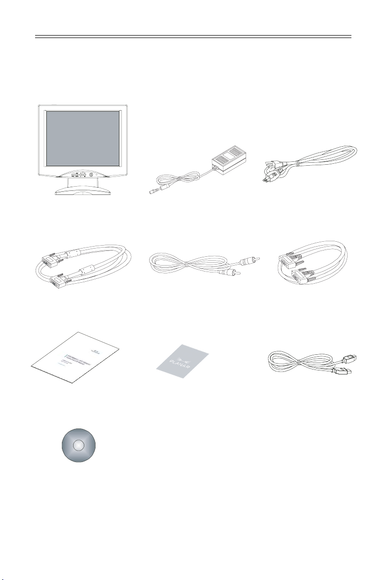
Package Overview
LCD Display
VGA Signal Cable
User’s Guide
Touchscreen Driver
Installation CD-ROM
Power Adapter
Audio-In Cable
Landing Strip USB Cable
Power Cord
RS-232 Serial Cable
(for PT1700M,
PT1701M)
(for PT1700MU,
PT1701MU)
6 PT1700M(U) and PT1701M(U) User’s Guide (020-0410-00 A)
Page 7
Installation
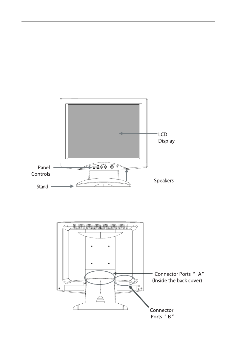
Product Overview
• F• F
rr
onon
t t
VV
r
on
rr
onon
ear ear
ear
ear ear
t
t t
VV
V
VV
iewiew
V
iew
VV
iewiew
iewiew
iew
iewiew
• F
• F• F
• R• R
• R
• R• R
PT1700M(U) and PT1701M(U) User’s Guide (020-0410-00 A) 7
Page 8
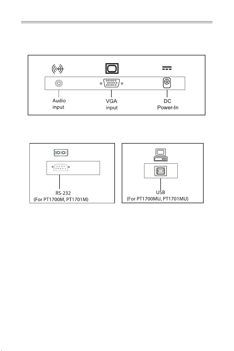
• C• C
• C
• C• C
• C• C
• C
• C• C
onneconnec
onnec
onneconnec
onneconnec
onnec
onneconnec
tt
or Por P
t
or P
tt
or Por P
tt
or Por P
t
or P
tt
or Por P
oror
or
oror
oror
or
oror
ts ts
ts
ts ts
ts ts
ts
ts ts
“B“B
“B
“B“B
““
AA
””
“
A
”
““
AA
””
””
”
””
8 PT1700M(U) and PT1701M(U) User’s Guide (020-0410-00 A)
Page 9
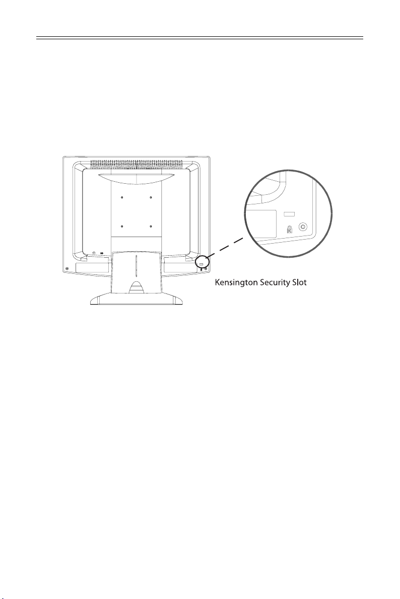
• Kensington Security Slot• Kensington Security Slot
• Kensington Security Slot
• Kensington Security Slot• Kensington Security Slot
The monitor can be secured to your desk or any other fixed object with
Kensington lock security products. The kensington lock is not included.
PT1700M(U) and PT1701M(U) User’s Guide (020-0410-00 A) 9
Page 10

• VESA Mount your monitor• VESA Mount your monitor
• VESA Mount your monitor
• VESA Mount your monitor• VESA Mount your monitor
This monitor conforms to the VESA Flat Panel Mounting Physical Mounting
Interface Standard which defines a physical mounting interface for flat panel
monitors, and corresponding standards for flat panel monitor mounting devices,
such as wall and table arms.The VESA mounting interface is located on the back
of your monitor. To mount the monitor on a swing arm or other mounting
fixture, follow the instruction included with the mounting fixture to be used.
Note!Note!
Note!
Note!Note!
!
Ì
Please select the proper screws!
The distance between the back cover surface and the bottom of the screw
hole is 8mm. Please use a M4 screw.
10 PT1700M(U) and PT1701M(U) User’s Guide (020-0410-00 A)
Page 11

Start your Installation
• Remove the Back Cover• Remove the Back Cover
• Remove the Back Cover
• Remove the Back Cover• Remove the Back Cover
Please follow these instructions to remove the cover on the back panel of the
LCD so that you can connect the cables in ”Connector Ports B.”
1. To remove the back cover, follow the arrows in Figure A and press with both
your thumbs. The cover should be removed by pressing firmly.
2. Follow the instruction on P.12 (Figure 11.1) to connect the cables in
”Connector Ports B.”
3. Fix the cover back to the LCD. You may also keep the cables in order with the
included cable organizer.
Note!Note!
Note!
Note!Note!
!
Ì
You can place the LCD flat horizontally to make it easier to connect the
cables. Please make sure that you place it on an even surface lest the LCD
should be damaged by scratches or collision.
PT1700M(U) and PT1701M(U) User’s Guide (020-0410-00 A) 11
Page 12

Connecting the display
To configure this monitor, please refer to the following figure and
procedures.
1. Be sure all equipment is off.
2. Connect the DC power cord to the power connector. Plug one end of the
AC power cord into the power adapter, and the other end into an electrical
outlet(1).
3. For the PC with Analog graphics output: connect the VGA signal cable from
display VGA input connector to the 15-pin connector of your host computer
and tighten the screws(2).
4. WARNING For PT1700(1)MU Monitor: Do not connect the USB cable from USB
port of your display to the USB port of your computer until the touch screen
software driver has been installed.
5. After driver installation for PT1700(1)MU : Re-connect the USB cable from USB
port of your display to the USB port of your computer.
6. Turn on your computer, display and video source.
(Figure 1.1 and Figure 1.2)(Figure 1.1 and Figure 1.2)
(Figure 1.1 and Figure 1.2)
(Figure 1.1 and Figure 1.2)(Figure 1.1 and Figure 1.2)
Notice:Notice:
Notice: To ensure the LCD display works well with your computer, configure
Notice:Notice:
the display mode of your graphic card, less than or equal to 1280 x
1024 resolution and make sure the timing of the display mode is
compatible with the LCD panel. “Compatibility Modes” of this LCD
panel are listed in the appendices for your reference.
12 PT1700M(U) and PT1701M(U) User’s Guide (020-0410-00 A)
Page 13

FF
igurigur
F
igur
FF
igurigur
e 1.1e 1.1
e 1.1
e 1.1e 1.1
PT1700M(U) and PT1701M(U) User’s Guide (020-0410-00 A) 13
Page 14

Figure 1.2Figure 1.2
Figure 1.2
Figure 1.2Figure 1.2
14 PT1700M(U) and PT1701M(U) User’s Guide (020-0410-00 A)
Page 15

User Controls
Front Panel Controls
PT1700M(U) and PT1701M(U) User’s Guide (020-0410-00 A) 15
Page 16

How to Use the OSD Menus
1. Press the “Menu” button to pop up the on-screen menu and to select
between the four Main Menus.
2. Choose the adjustment items by pressing the “Select/Auto” button.
3. Adjust the value of the adjustment items by pressing the “_” or “`” button.
4. The OSD menu will automatically close, if you have left it idle for a pre-set
time.
16 PT1700M(U) and PT1701M(U) User’s Guide (020-0410-00 A)
Page 17

On-Screen Display Menus
Main OSD Menu:
AA
utut
oo
--
AA
ut
utut
o
oo
djustmendjustmen
-
A
djustmen
--
AA
djustmendjustmen
`
A
AA
Choose this function to obtain an optimum image.
ContrastContrast
`
Contrast
ContrastContrast
Adjust the contrast of the display image.
BrightnessBrightness
`
Brightness
BrightnessBrightness
Adjusts the brightness of the image.
tt
t
tt
Horizontal PositionHorizontal Position
`
Horizontal Position
Horizontal PositionHorizontal Position
Changes the horizontal position of the image.
Vertical PositionVertical Position
`
Vertical Position
Vertical PositionVertical Position
Changes the vertical position of the image.
ClockClock
`
Clock
ClockClock
Changes the display data frequency to match the frequency of your
graphic card. When you are experiencing vertical flickering bar, use this
function to make an adjustment.
PhasePhase
`
Phase
PhasePhase
Synchronizes the signal timing of the display to that of the graphic card.
When you are experiencing vertical flickering image, use this function to
make an adjustment.
PT1700M(U) and PT1701M(U) User’s Guide (020-0410-00 A) 17
Page 18

On-Screen Display Menus
Second OSD Menu:
Display ModeDisplay Mode
`
Display Mode
Display ModeDisplay Mode
Select this function to view the display resolution, vertical refresh, and
horizontal scan of the current mode.
OSD OOSD O
ff-ff-
TT
`
OSD O
OSD OOSD O
Adjusts the time period for OSD menu to disappear.
LanguageLanguage
`
Language
LanguageLanguage
Choose the language you need.
ff-
ff-ff-
T
TT
imeime
ime
imeime
SharShar
`
`
pnesspness
Shar
pness
SharShar
pnesspness
Adjust the sharpness of the image.
ResetReset
Reset
ResetReset
Returns the display parameters of the current mode to its factory default
settings.
18 PT1700M(U) and PT1701M(U) User’s Guide (020-0410-00 A)
Page 19

On-Screen Display Menus
Third OSD Menu:
VV
olumeolume
`
V
olume
VV
olumeolume
Controls the sound volume.
MutMut
`
ee
Mut
e
MutMut
ee
Disables the sound immediately.
PT1700M(U) and PT1701M(U) User’s Guide (020-0410-00 A) 19
Page 20

On-Screen Display Menus
Fourth OSD Menu:
Color SettingColor Setting
`
Color Setting
Color SettingColor Setting
Adjusts the color temperature.
Color Adjustment-RedColor Adjustment-Red
`
Color Adjustment-Red
Color Adjustment-RedColor Adjustment-Red
It allows you to adjust the red color of the display.
Color Adjustment-GreenColor Adjustment-Green
`
Color Adjustment-Green
Color Adjustment-GreenColor Adjustment-Green
It allows you to adjust the green color of the display.
Color Adjustment-BlueColor Adjustment-Blue
`
Color Adjustment-Blue
Color Adjustment-BlueColor Adjustment-Blue
It allows you to adjust the blue color of the display.
20 PT1700M(U) and PT1701M(U) User’s Guide (020-0410-00 A)
Page 21

Appendix
Troubleshooting
If you are experiencing trouble with the LCD display, refer to the following. If
the problem persists, please contact your local dealer or visit Planar Support at
www.planar.com/support. See support contact information on rear cover.
PP
rr
oblem: No image apoblem: No image ap
P
r
oblem: No image ap
PP
rr
oblem: No image apoblem: No image ap
` Check that all the I/O and power connectors are installed correctly and
well connected as described in the “Installation” section.
` Make sure the pins of the connectors are not crooked or broken.
PP
rr
oblem: Poblem: P
P
r
oblem: P
PP
rr
oblem: Poblem: P
` Check to see if the resolution of your computer is higher than that of the
` Reconfigure the resolution of your computer to make it less than or equal
PP
rr
oblem: Ioblem: I
P
r
oblem: I
PP
rr
oblem: Ioblem: I
` Use “Frequency” to make an adjustment.
` Check and reconfigure the display mode of the vertical refresh rate of
arar
tial image or inctial image or inc
ar
tial image or inc
arar
tial image or inctial image or inc
LCD display.
to 1280 x 1024.
mage has flickermage has flicker
mage has flicker
mage has flickermage has flicker
your graphic card to make it compatible with the LCD display.
pears on scrpears on scr
pears on scr
pears on scrpears on scr
oror
rr
ecec
or
r
ec
oror
rr
ecec
ing ving v
erer
ing v
er
ing ving v
erer
een.een.
een.
een.een.
tly displatly displa
tly displa
tly displatly displa
tical line barstical line bars
tical line bars
tical line barstical line bars
yy
ed imageed image
y
ed image
yy
ed imageed image
..
.
..
..
.
..
PP
rr
oblem: Ioblem: I
P
r
oblem: I
PP
rr
oblem: Ioblem: I
` Use “Phase” to make an adjustment.
Problem: Image is scrollingProblem: Image is scrolling
Problem: Image is scrolling
Problem: Image is scrollingProblem: Image is scrolling
` Check and make sure the VGA signal cable (or adapter) is well connected.
` Check and reconfigure the display mode of the vertical refresh rate of
PP
rr
oblem: Ioblem: I
P
r
oblem: I
PP
rr
oblem: Ioblem: I
` Use “Phase” to make an adjustment. If the problem persists, use “Clock” to
mage is unstable and flickermage is unstable and flicker
mage is unstable and flicker
mage is unstable and flickermage is unstable and flicker
your graphic card to make it compatible with the LCD display.
mage ghosting (charmage ghosting (char
mage ghosting (char
mage ghosting (charmage ghosting (char
make an adjustment.
PT1700M(U) and PT1701M(U) User’s Guide (020-0410-00 A) 21
acac
ac
acac
inging
ing
inging
tt
ers and gers and g
t
ers and g
tt
ers and gers and g
rr
aphics)aphics)
r
aphics)
rr
aphics)aphics)
Page 22

Warning Signal
There are instances when you will see warning messages from the LCD screen.
This occurs when the LCD is unable to receive the exact signal from the
computer graphic card.
There are three instances when this may happen. Please check the cable
connections or contact your local dealer or Planar Support for more
information.
No SigNo Sig
`
`
nalnal
No Sig
nal
No SigNo Sig
nalnal
The LCD has been powered on but it isn’t receiving a signal from the
computer graphic card. Check all the power switches, power cables, and
VGA signal cable.
GG
oing toing t
oing t
oing toing t
o Sleepo Sleep
o Sleep
o Sleepo Sleep
G
GG
The LCD is under the power saving mode. In addition, the LCD will go
into this sleep mode when experiencing a sudden signal
disconnecting problem.
Out of ROut of R
`
Out of R
Out of ROut of R
The signal of the computer graphic card is incompatible with the LCD.
This occurs when the graphic card signal is not one of the compatibility
modes listed in the Appendices of this manual.
angeange
ange
angeange
22 PT1700M(U) and PT1701M(U) User’s Guide (020-0410-00 A)
Page 23

Product Dimensions
PT1700M(U) and PT1701M(U) User’s Guide (020-0410-00 A) 23
Page 24

Compatibility Modes
MM
odeode
M
ode
MM
odeode
RR
esolutionesolution
R
esolution
RR
esolutionesolution
VV
.F.F
V
.F
VV
.F.F
rr
equencequenc
r
equenc
rr
equencequenc
(H(H
z)z)
(H
z)
(H(H
z)z)
yy
H.FH.F
rr
H.F
H.FH.F
equencequenc
r
equenc
rr
equencequenc
(kH(kH
(kH
(kH(kH
y
yy
yy
y
yy
z)z)
z)
z)z)
IBM VGA
IBM VGA
IBM VGA
IBM VGA
VESA VGA
VESA VGA
VESA SVGA
VESA SVGA
VESA SVGA
VESA SVGA
VESA XGA
VESA XGA
VESA XGA
VESA SXGA
VESA SXGA
640 x 350
640 x 400
640 x 480
720 x 400
640 x 480
640 x 480
800 x 600
800 x 600
800 x 600
800 x 600
1024 x 768
1024 x 768
1024 x 768
1280 X 1024
1280 X 1024
70
70
60
70
72
75
56
60
72
75
60
70
75
60
75
31.5
31.5
31.5
31.5
37.9
37.5
35.2
37.9
48.1
46.9
48.4
56.5
60.0
64.0
80.0
Apple Mac
Apple Mac
Apple Mac
Apple Mac
640 x 480
640 x 480
832 x 624
1024 x 768
67
67
75
75
24 PT1700M(U) and PT1701M(U) User’s Guide (020-0410-00 A)
34.9
35.0
49.7
60.2
Page 25

Touchscreen Driver Installation
Driver Installation for PT1700MU:Driver Installation for PT1700MU:
Driver Installation for PT1700MU:
Driver Installation for PT1700MU:Driver Installation for PT1700MU:
RR
esistivesistiv
R
esistiv
RR
esistivesistiv
Please note: These monitors are Microsoft Windows® HID (Human Interface
Device) compatible. No additional software driver is required for general
operation of the touchscreen.
A special calibration tool can be installed for improved touch position accuracy. See
II
nstallanstalla
I
nstalla
II
nstallanstalla
OO
O
OO
7.00 I7.00 I
7.00 I
7.00 I7.00 I
with USB Cwith USB C
with USB C
with USB C
with USB C
Please note: These monitors are Microsoft HID (Human Interface Device)
compatible. The calibration driver is not required for general operation of the
touchscreen.
This calibration tool is for optimization of touch performance for the
touchscreen to meet the 1% TPE accuracy specification.
e e
TT
e
T
e e
TT
OO
ptional Mptional M
O
ptional M
OO
ptional Mptional M
tion Ption P
tion P
tion Ption P
ptional Drptional Dr
ptional Dr
ptional Drptional Dr
nstallanstalla
nstalla
nstallanstalla
ouchscrouchscr
ouchscr
ouchscrouchscr
rr
ococ
essess
r
oc
ess.
rr
ococ
essess
iviv
er Mer M
iv
er M
iviv
er Mer M
tion Ption P
tion P
tion Ption P
onneconnec
onnec
onneconnec
een with USB Ceen with USB C
een with USB C
een with USB Ceen with USB C
TMTM
TM
icricr
icr
icricr
icricr
icr
icricr
rr
ococ
r
oc
rr
ococ
tiontion
tion
tiontion
oo
o
oo
oo
o
oo
TMTM
TT
ouchouch
T
TT
TT
T
TT
ess fess f
ess f
ess fess f
USB HID C USB HID C
ouch
USB HID C
ouchouch
USB HID C USB HID C
TMTM
TM
TMTM
ouchouch
ouch
ouchouch
USB HID C USB HID C
USB HID C
USB HID C USB HID C
or PT1700MU: Ror PT1700MU: R
or PT1700MU: R
or PT1700MU: Ror PT1700MU: R
onneconnec
onnec
onneconnec
alibralibr
alibr
alibralibr
tiontion
tion
tiontion
aa
tion tion
a
tion
aa
tion tion
alibralibr
alibr
alibralibr
esistivesistiv
esistiv
esistivesistiv
aa
tion tion
a
tion
aa
tion tion
TT
ool vool v
T
ool v
TT
ool vool v
e e
e
e e
ersion 7.00ersion 7.00
ersion 7.00
ersion 7.00ersion 7.00
TT
ool ool
VV
ersionersion
T
ool
V
ersion
TT
ool ool
VV
ersionersion
TT
ouchscrouchscr
T
ouchscr
TT
ouchscrouchscr
eeneen
een
eeneen
The following Microsoft Windows® operating systems are supported by this
MM
icricr
osofosof
t t
WW
indoindo
ww
software driver:
1. WARNING Disconnect the USB cable between the display and PC before
installing optional USB HID Calibration Driver.
2. Open the CD-Rom.
3. Select the LA1500RTR, LA1710RTR, PT1500MU/1700MU Calibration
Option link.
4. The driver file will automatically open.
5. Follow the installation instructions for the MicroTouch HID Calibration
procedure.
M
icr
osof
t
MM
icricr
W
osofosof
t t
WW
PT1700M(U) and PT1701M(U) User’s Guide (020-0410-00 A) 25
indo
indoindo
s® 98SEs® 98SE
w
s® 98SE
ww
s® 98SEs® 98SE
, M, M
ee
, 2000, and XP, 2000, and XP
, M
e
, 2000, and XP
, M, M
ee
, 2000, and XP, 2000, and XP
..
.
..
Page 26

DrDr
iviv
er Ier I
Dr
DrDr
RS-232 Serial Connection.RS-232 Serial Connection.
RS-232 Serial Connection.
RS-232 Serial Connection.RS-232 Serial Connection.
Touch driver information is located on the enclosed CD-ROM for the following
operating systems:
4.0, Windows Me, and Windows 9X.4.0, Windows Me, and Windows 9X.
4.0, Windows Me, and Windows 9X.
4.0, Windows Me, and Windows 9X.4.0, Windows Me, and Windows 9X.
1. Open the CD-Rom.
2. Select the link for your monitor model PT1700M.
3. The driver will automatically open.
4. Select the “TW564SR4.exe” file.
5. Select “unzip”.
6. Double click the “setup.exe” file.
7. Follow the installation instructions.
8. If the touch screen driver does not automatically load, restart the computer
nstallanstalla
iv
er I
nstalla
iviv
er Ier I
nstallanstalla
operating system.
tion ftion f
or PT1700M: Ror PT1700M: R
tion f
or PT1700M: R
tion ftion f
or PT1700M: Ror PT1700M: R
MM
icricr
osofosof
M
icr
osof
MM
icricr
osofosof
esistivesistiv
e e
TT
WW
W
WW
e
T
e e
TT
indoindo
indo
indoindo
ouchscrouchscr
ouchscr
ouchscrouchscr
ww
w
ww
esistiv
esistivesistiv
t t
WW
indoindo
ww
s® XPs® XP
t
W
indo
t t
WW
indoindo
w
s® XP
ww
s® XPs® XP
, ,
,
, ,
s 2000, s 2000,
s 2000,
s 2000, s 2000,
een witheen with
een with
een witheen with
WW
indoindo
ww
W
indo
w
WW
indoindo
ww
s NTs NT
s NT
s NTs NT
26 PT1700M(U) and PT1701M(U) User’s Guide (020-0410-00 A)
Page 27

DrDr
iviv
er Ier I
Dr
DrDr
USB Connection or RS-232 Serial Connection.USB Connection or RS-232 Serial Connection.
USB Connection or RS-232 Serial Connection.
USB Connection or RS-232 Serial Connection.USB Connection or RS-232 Serial Connection.
Touch driver information is located on the enclosed CD-ROM for the following
operating systems:
Windows Me, and Windows 9X and Linux.Windows Me, and Windows 9X and Linux.
Windows Me, and Windows 9X and Linux.
Windows Me, and Windows 9X and Linux.Windows Me, and Windows 9X and Linux.
1. Open the CD-Rom.
2. Select the link for your monitor model and PC operating system you are using
3. The driver will automatically open.
4. Follow the installation instructions.
5. When driver installation is complete, reconnect the USB cable.
6. Open the 3M Touchware icon located on your PC‘s desktop.
7. Select the “Calibrate” tab and follow the calibration instructions.
8. If the touch screen driver does not automatically load, restart the computer
nstallanstalla
iv
er I
nstalla
iviv
er Ier I
nstallanstalla
Disconnect the USB Cable between the display and PC before installingDisconnect the USB Cable between the display and PC before installing
Disconnect the USB Cable between the display and PC before installing
Disconnect the USB Cable between the display and PC before installingDisconnect the USB Cable between the display and PC before installing
the Drthe Dr
iviv
the Dr
iv
the Drthe Dr
iviv
for either Windows or Linux.
operating system.
erer
er
erer
..
.
..
tion ftion f
or PT1701M(U): Cor PT1701M(U): C
tion f
or PT1701M(U): C
tion ftion f
or PT1701M(U): Cor PT1701M(U): C
MM
icricr
osofosof
icr
icricr
osof
osofosof
t t
t
W
t t
M
MM
WW
WW
indoindo
indo
indoindo
ww
w
ww
s® XPs® XP
s® XP
s® XPs® XP
apacitivapacitiv
apacitiv
apacitivapacitiv
, ,
WW
indoindo
,
W
indo
, ,
WW
indoindo
e e
e
e e
ww
s 2000, s 2000,
w
s 2000,
ww
s 2000, s 2000,
TT
ouch scrouch scr
T
ouch scr
TT
ouch scrouch scr
WW
indoindo
W
indo
WW
indoindo
een witheen with
een with
een witheen with
ww
s NT 4.0,s NT 4.0,
w
s NT 4.0,
ww
s NT 4.0,s NT 4.0,
FF
or Linux users open the or Linux users open the
F
or Linux users open the
FF
or Linux users open the or Linux users open the
“readme.txt” file for installation instructions.“readme.txt” file for installation instructions.
“readme.txt” file for installation instructions.
“readme.txt” file for installation instructions.“readme.txt” file for installation instructions.
““
TT
WLinux 5.62.1”WLinux 5.62.1”
“
T
WLinux 5.62.1”
““
TT
WLinux 5.62.1”WLinux 5.62.1”
PT1700M(U) and PT1701M(U) User’s Guide (020-0410-00 A) 27
dir dir
ecec
tt
or and open theor and open the
dir
ec
t
or and open the
dir dir
ecec
tt
or and open theor and open the
Page 28

Planar Systems, Inc.Planar Systems, Inc.
Planar Systems, Inc.
Planar Systems, Inc.Planar Systems, Inc.
Customer Service
24x7 Online 24x7 Online
24x7 Online
24x7 Online 24x7 Online
TT
el:el:
T
el: 1-866-PLANAR1 (866) 752-6271 Option #2
TT
el:el:
Email:Email:
Email: PlanarSupport@planar.com
Email:Email:
Hours:Hours:
Hours: M-F, 5am - 5pm Pacific Time
Hours:Hours:
© 2005
Other brands and names are the property of their respective owners.
Technical information in this document is subject to change without notice.
TT
echnical Supechnical Sup
T
echnical Sup
TT
echnical Supechnical Sup
Planar Systems, Inc. 04/05Planar Systems, Inc. 04/05
Planar Systems, Inc. 04/05 Planar is a registered trademark of Planar Systems, Inc.
Planar Systems, Inc. 04/05Planar Systems, Inc. 04/05
porpor
t:t:
por
t: http://www.planar.com/support
porpor
t:t:
Document No. Document No.
Document No.
Document No. Document No.
020-0410-00 Rev A 020-0410-00 Rev A
020-0410-00 Rev A
020-0410-00 Rev A 020-0410-00 Rev A
P/N:36.56905.016 Rev.B
 Loading...