

Page 1

PT1510MX
Touchscreen LCD Monitors
USER’S GUIDE
www.planar.com
Page 2

Page 3
Important Recycle Instruction:
LCD Lamp(s) inside this product contain mercury. This product may contain
other electronic waste that can be hazardous if not disposed of properly. Recycle or
dispose in accordance with local, state, or federal Laws. For more information,
contact the Electronic Industries Alliance at WWW.EIAE.ORG
disposal information check WWW.LAMPRECYCLE.ORG
. For lamp specific
.
.
Page 4

Page 5

Table of Contents
Usage Notice
Precautions.........................................................................................2
Introduction
About Planar’s PT1510MX..................................................................3
Touch Screen for PT1510MX……………………………………………..4
Package Overview..............................................................................5
Installation
Product Overview................................................................................6
VESA Mount your monitor………………………………………………..9
Start Your Installation…………………………………………………….10
User Controls
Front Panel Controls.........................................................................14
How to Use the OSD Menus.............................................................15
On-Screen Display Menus For PT1510MX Product..........................16
Appendices
Troubleshooting.................................................................................17
Warning Signal..................................................................................18
Product Dimensions..........................................................................19
Compatibility Modes..........................................................................20
Touch Screen Driver Installation………………………………………..21
1
Page 6
Usage Notice
Warning
Warning
Precautions
Follow all warnings, precautions and maintenance as recommended
in this user’s manual to maximize the life of your unit.
Do:
Don’t:
- To prevent the risk of fire or shock hazards, do not
expose this product to rain or moisture.
- Please do not open or disassemble the product as
this may cause electric shock.
Turn off the product before cleaning.
Touch screen surface may be cleaned using a soft cle an cloth
moistened with mild window glass commercial cleaners or 50/50
mixture of water and isopropyl alcohol.
Use a soft cloth moistened with mild detergent to clean the display
housing.
Use only high quality and safety approved AC/DC adapter that
comes with your monitor.
Disconnect the power plug from AC outlet if the product is not going
to be used for an extended period of time.
Do not touch the LCD Display screen surface with sharp or hard
objects.
Do not use abrasive cleaners, waxes or solvents for your cleaning.
Do not operate the product under the following conditions:
- Extremely hot, cold or humid environment.
- Areas susceptible to excessive dust and dirt.
- Near any appliance generating a strong magnetic field.
- In direct sunlight.
2
Page 7

3
Introduction
About Planar’s PT1510MX
The PT1510MX is a 15” flat panel screen with an active matrix,
thin-film transistor (TFT) liquid crystal display (LCD).
Features include:
Direct Analog signal input
Active matrix TFT LCD technology
1024x768 XGA resolution
15” diagonal screen size
31.5 ~ 60 kHz horizontal scan
56 ~ 75 Hz high refresh rate
Auto adjustment function
Multilingual OSD user controls
VESA DPMS power saving
Kensington security slot
Built-in speakers for multimedia application
75 mm VESA mount
Removable base for flexible mounting solutions
Gunze 5-wire Resistive touch screen with dual RS-232 Serial/USB
controller
Built-in Speakers – 1W/ cha nnel
Page 8

Touch Screen for PT1510MX
Gunze analog 5-wire resistive touch screen for finger and stylus input
Surface: Anti-glare treatment
Interface: Dual RS-232 Serial/USB controller
Durability: 35 million touches at a single point
Hardness of surface: 2H MIN (As provided in JIS K 5400)
Operating force: 0.10~1.96N(10g~200g when using a silicon tipped pen
with a 3 mm radius and a hardness of 60 degree.)
Transmissivity: 78% (Typ.)
Driver: Gunze® Touch Panel Device Driver: TBDD. Supports Microsoft
Windows® Me. 2000. XP
4
Page 9
5
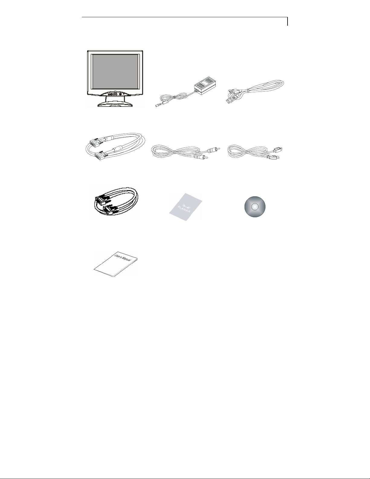
Package Overview
LCD Display Power Adapter Power Cord
VGA Signal Cable Audio-in Cable USB Cable
RS-232 Cable Landing Strip Touchscreen Driver
Installation CD-ROM
User’s Guide
Page 10
6
Installation
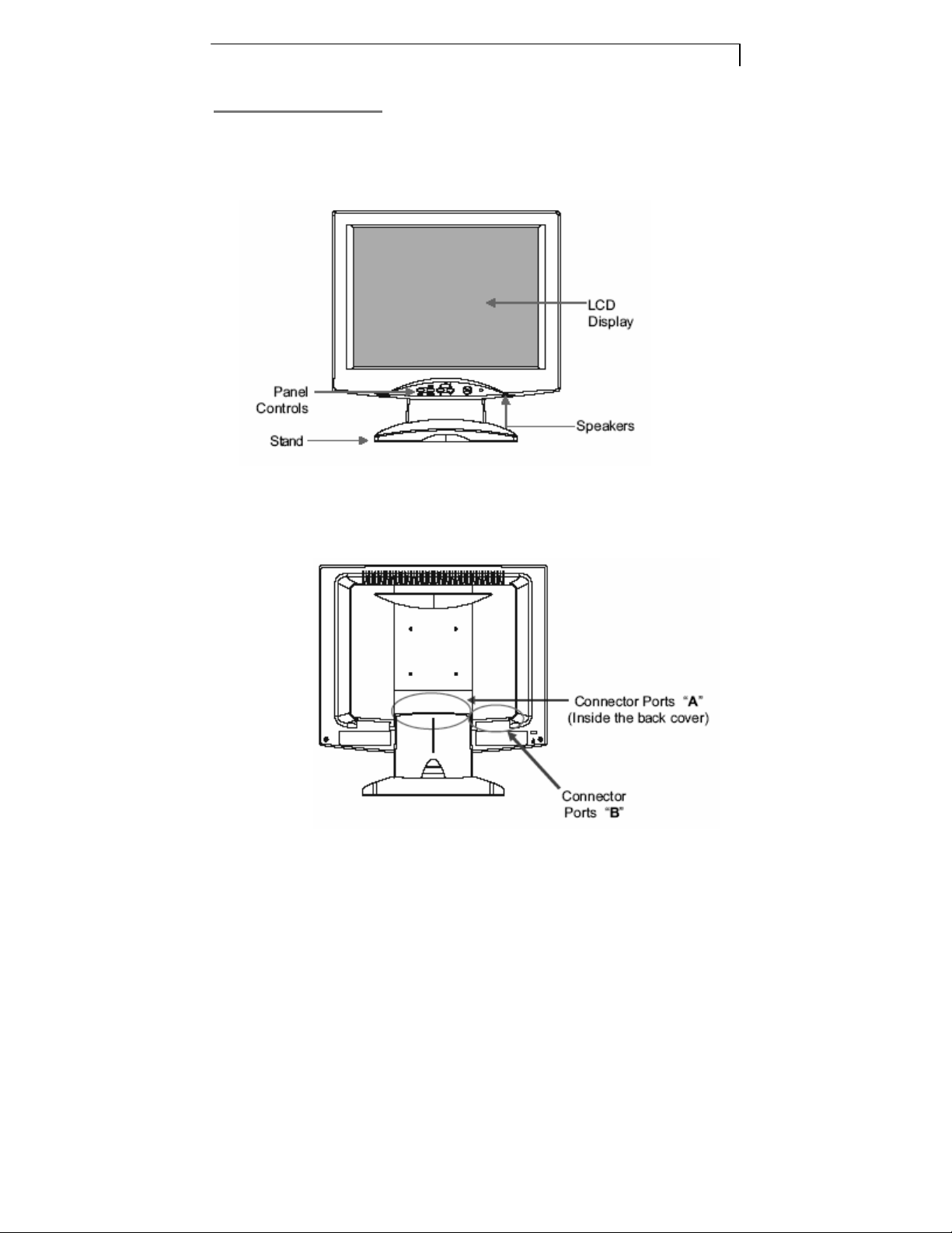
Product Overview
Front View
Back View
Page 11

¡ Connector Ports “A”
¡ Connector Ports “B”
7
RS-232 USB
Page 12

8
Kensington Security Slot
The monitor can be secured to your desk or any other fixed object with
Kensington lock security products. The Kensington lock is not included.
Page 13

9
VESA Mount your monitor
This monitor conforms to the VESA Flat Panel Mounting Physical Mounti ng
Interface S t andard which d efines a physic al mount ing inte rface for f lat p anel
monitors, and corresponding standards for flat panel monitor mounting
devices, such as wall and t able a rms. The VESA mountin g interf ace is
located on the back of your monit or.
To mount the monitor on a swin g arm or ot her mo unting f ixture, fol low the
instructions included with the mounting fixture to be used.
Warning!
Please select the proper screws!
The distance between the back cover surface and the bottom of the
screw hole is 8mm. Please use M4 screw diameter with a maximum
length of 8 mm.
Page 14

0
St art Your Installation
¡ Remove the Back Cover
Please follow these instructions to remove the cover on the back panel of
the LCD so that you can connect the cables in “Connector Ports B.”
1. To remove the back cover, follow the arrows in Figure A and pres s with
both your thumbs. The cover should be removed by pressing firmly
along the edges while pulling on the cover .
2. Follow the instructions on P. 11 ( Figure 11.1 ) to connect the cables in
“Connector Ports B.”
3. Fix the cover back to the LCD by pressing firmly until the tabs snap into
place. You may also keep the cables in order by using the cable
organizer.
1
Page 15

Connecting the Display (Figure 11.1, 11.2)
To setup this display, please refer to the following figure and procedur es.
1. Be sure all equipment is turned off.
2. Connect the DC power cord to the power connector on the monitor; plug
one end of the AC power cord into the power adapter, and the other end
into an electrical outlet (11.1n).
3. Connect the VGA sign al cable from the display’s VGA input connector to
the 15-pin connector of your host computer and tighten the screws
(11.1Y).
4. Connect the Audio-In cable from the audio input port of your display to
the Audio-out port of your compute r (11.1Z).
5. Connect the RS-232 or USB cable from the RS-232 or USB port of your
display to the RS-232 port (1 1.1[) or USB port (11.2\) of your computer.
6. Configure the touch screen. Refer to the “Touch Screen Driver
Installation section on P. 21.
7. Once the touch screen is configured, monitor is ready for use.
11
To ensure the LCD display works well with your computer, please
configure the display mode of your graphics card to make it less
than or equal to 1024 x 768 resolution and make sure the timing of
the display mode is compatible with the LCD display.
We have listed the compatible “Video Modes” of y our LCD display
in the appendix for your reference.
Page 16

12
Page 17

3
1
Page 18

User Controls
Front Panel Controls
No / Icon
Control Function
14
X MENU
YSELECT/AUTO
Z W
[
\
]
X
Menu button Display the OSD menus
Select – To select the adjustment items from
Select/Auto
Brightness
Minus/Minus
Brightness
Plus/Plus
Power Switch
Power LED
OSD menus.
Auto – To activate the “Auto Adjustment”
function to obtain an optimum image.
1. Decreases the brightness of the display
image.
2. Decreases value of the adjustment items.
1. Increases the brightness of the display
image.
2. Increases value of the adjustment items.
Switches on/off the power of the LCD
display.
1. Green indicates the display is turned on.
2. Amber indicates the display is in
power-saving mode.
Page 19

5
How to Use the OSD Menus
1.
Press the "MENU" button to pop up the “on-screen menu” and to select
among the four Main Menus.
2. Choose the adjustment items by pressing the “Select/Auto” button.
3. Adjust the value of the adjustment items by pressing the “W”or “X“ button.
4. The OSD menu will automatically close, if you have left it idle for a
pre-set time.
1
Page 20

6
On-Screen Display Menus for the PT1510MX Product
Main Menu Menu Level 2 Function Description Remark
Brightness
Contrast
LCD Adjustment Clock
Phase
H. Position Changes the horizontal position of the image.
V. Position Changes the vertical position of the image.
Color Temperature
ECO mode
Language
Other Setup Smooth Adjusts the smoothness of the image.
OSD H. Position Changes the horizontal position of the OSD.
OSD V. Position Changes the vertical position of the OSD.
OSD Transparency Changes the opaqueness of the OSD background.
OSD Time out
Volume Adjusts the sound volume. Default 50
Mode Message Enables or disables the display of information.
Reset
Exit Exit the OSD menu.
Choose this function to adjust the brightness of the
image.
Choose this function to adjust the contrast of the
image.
Minimizes any vertical bars or stripes visible on the
screen.
Minimizes any horizontal distortion and clears or
sharpens the displayed characters.
Opens the color temperature sub-menu where you
can select the desired color temperature of the
image. ( SRGB / 9300K / 7200K / 6500K / 5000K /
USER )
Enables or disables the power savings mode.
( On/Off )
Opens the language sub-menu where you can
select the desired language of the OSD.
Adjusts the amount of time the OSD menu will be
displayed for after inactivity.
Resets the display parameters back to its factory
default settings.
Default 30
Default 40
Default is
7200K
Default 30
1
Page 21

Appendix
Troubleshooting
If you are experiencing trouble with the LCD display , refer to the following. If
the problem persists, please contact your local dealer or our service center.
Problem: No image appears on screen.
Check that all the I/O and power connectors are correctly and well
connected as described in the “Installation” section.
Make sure the pins of the connectors are not crooked or broken.
Problem: Partial Image or incorrectly displayed the image.
Check to see if the resolution of your computer is higher than that of the
LCD display.
Reconfigure the resolution of your computer to make it less than or equal
to 1024 x 768.
Problem: Image has vertical flickering line bars.
Use "Clock" to make an adjustment.
Check and reconfigure the display mode of the vertical refresh rate of your
graphic card to make it compatible with the LCD display.
17
Problem: Image is unstable and flickering
Use "Phase" to make an adjustment.
Problem: Image is scrolling
Check and make sure the VGA signal cable (or adapter) is securely
connected.
Check and reconfigure the display mode of the vertical refresh rate of your
graphics card to make it compatible with the LCD Display.
Problem: Vague image (characters and graphics)
Use "Clock" to make an adjustment. If this problem still exists, use “Phase”
to make an adjustment.
Page 22

8
Warning Signal
If you see warning messages on your LCD screen, this means that
the LCD display cannot receive a clean signal from the computer
graphics card.
There may be two sources for this problem. Please check the cable
connections or contact Planar for more information.
No Signal
This message means that the LCD Display has been powered on but it
cannot receive any signal from the computer graphics card. Check all the
power switches, power cables, and VGA signal cable.
Out of Range
This message means that the signal of the computer graphic card is not
compatible with the LCD display. When the signal is not included in the
“Video Modes” list we have listed in the Appendices of this manual, the
LCD display will display this message.
1
Page 23

9
Product Dimensions
1
Page 24

0
Compatibility Modes
2
Mode Resolution
IBM VGA 640 x 350 70 31.5
IBM VGA
IBM VGA
IBM VGA
VESA VGA 640 x 480 72 37.9
VESA VGA 640 x 480 75 37.5
VESA SVGA 800 x 600 56 35.2
VESA SVGA
VESA SVGA
VESA SVGA
VESA XGA 1024 x 768 60 48.4
VESA XGA
VESA XGA
Apple Mac LC 640 x 480 67 34.9
640 x 400 70
720 x 400 70
640 x 480 60
800 x 600
800 x 600
800 x 600
1024 x 768
1024 x 768
V. Frequency
(Hz)
60 37.9
72 48.1
75 46.9
70 56.5
75 60.0
H. Frequency
(kHz)
31.5
31.5
31.5
Apple Mac II 640 x 480 67 35.0
Apple Mac
Apple Mac
832 x 624 75 49.7
1024 x 768 75 60.2
Page 25

Touch Screen Driver Installation
The touch driver is located on the enclosed CD-ROM for these
operating systems: Windows Me/2000/98/XP series.
21
Driver Installation Process:
1. Before your start to install the touch driver, please be sure the USB or the
RS-232 Serial cable is disconnected from the PC or the LCD display. Select
Setup.exe
2. Follow driver installation instructions.
3. After installation is complete, click Finish” and restart your computer to
complete installation.
Touch Panel Setting and Calibration:
1. After restarting your Windows, click “start” on the Windows toolbar.
2. Select “All Programs” and select “Gunze TPDD”.
3. Select “Adjust Settings”.
4. Select “Devices” tab and click “Add”.
5. Select “Gunze USB” if using a USB cable to connect between the monitor
and PC from the New Pointer Device menu.
See Figure 1
Page 26

6. For RS-232 Serial connection select “Gunze, AHL, Serial” and the COM
port to connect to the touch panel. See Figure 2
Figure 2
7. The operation area of the touchscreen can be assigned by the “Logical
desktop segment” function. Select your preference. Most common choice
will be “Whole Desktop” or “Primary Monitor” if you have multiple
monitors. See Figure 3
22
Figure 3
8. The Touch Panel Device Properties screen appears again. Click “Apply”.
See Figure 4.
Page 27

3
Figure 4
9. After clicking “Apply” connect your USB or RS-232 cable from your
2
display to your PC.
10. Steps 11-14 apply to USB connection only. For Serial connection go to
Step 15.
11. “Found New Hardware Wizard” screen will appear. Follow on screen
instructions.
12. When the “Hardware Installation” screen appears, click “Continue
Anyway”.
13. “Found New Hardware Wizard” screen re-appears in the case of MS
operating system Windows XP SP2. Choose “No, not this time” and click
“Next”.
14. “Found New Hardware Wizard” screen appears. Click “Finish”.
15. From the MS Windows Tool Bar Select “Start”. Select “Programs” and
select “Gunze TPDD” and select “Calibrate”. See Figure 5.
Page 28

Figure 5
16. Make contact with the “X” markings on the screen. Be sure your stylus or
finger is centered on each “X” point See Figure 6
24
Figure 6
17. Your touchscreen is now calibrated and is ready for operation.
Page 29

5
Uninstall Instructions
1. Click “start” in the Windows toolbar.
2. Select “Gunze TPDD” and select “TPDD Uninstall”.
3. Follow instructions.
4. Alternate method of uninstall is to use Windows “Control Panel”.
5. Select “Add or Remove Programs”.
6. Select “Gunze TPDD” and click “Change/Remove”.
7. Follow instructions.
2
Page 30

6
2
Page 31

27
Page 32

8
2
Planar Systems, Inc
Customer service
OnlineSupport: http://www.planar.com/support
Email:PlanarSupport@planar.com
Tel: 1-886-PLANAR-1 (1-886-752-6271)
Hours: M-F, 8am-8pm Eastern Time (5am-5pm Pacific Time)
© 2006 Planar Systems, lnc. 05/06 Planar is a reqistered trademark
of Planar System, Inc.
Other brands and names are the property of their respective owners.
Technical information in this document is subject to change without notice.
P/N:36.57724G001 Rev.A
020-0454-00A
 Loading...