

Page 1

Planar PT150M and PT150MU User's Manual www.planar.com
Page 2

Table of Contents
Usage Notice
Safety and Use............................................................................ 2
Introduction
About the Product ....................................................................... 3
Package Overview ...................................................................... 4
Installation
Product Overview ........................................................................ 5
VESA Mount your monitor .......................................................... 7
Start Your Installation .................................................................. 8
1
User Controls
Front Panel Controls ................................................................... 11
How to Use the OSD Menus ....................................................... 12
On-Screen Display Menus .......................................................... 13
Appendix
Troubleshooting ........................................................................... 17
Warning Signal ............................................................................ 18
Product Dimensions .................................................................... 19
Compatibility Modes ................................................................... 20
Page 3

2
Usage Notice
Warning- To prevent the risk of fire or shock hazards, do not
expose this product to rain or moisture.
Warning- Please do not open or disassemble the product as this
may cause electric shock.
Safety and Use
Follow all warnings, precautions and maintenance as recommended in this User’s Manual to maximize the life of your monitor.
Do:
Turn off the product before cleaning.
Use only a dry soft cloth or clean room wiper when cleaning the
LCD panel surface.
Use a soft cloth moistened with mild detergent to clean the
display housing.
Use only high-quality and safety-approved AC/DC power adapter.
Disconnect the power plug from AC outlet if the product is not
used for a long period of time.
Don’t:
Do not touch the LCD panel surface with sharp or hard objects.
Do not use abrasive cleaners, waxes or solvents for cleaning.
Do not operate the product under the following conditions:
- Extremely hot, cold or humid environment.
- Areas susceptible to excessive dust and dirt.
- Near any appliance generating a strong magnetic field.
- In direct sunlight.
Page 4

Introduction
About the Planar’s PT150M/PT150MU
This is a 15” flat panel screen with an active matrix, thin-film transistor
(TFT), liquid crystal display (LCD).
The monitor features include:
Direct analog signal input
Active matrix TFT LCD technology
1024 x 768 XGA resolution
15” viewable display area
31.5 ~ 60 kHz horizontal scan
56 ~ 75 Hz refresh rate
VESA mount holes (the stand is removable for flexible mounting)
3
Auto-adjustment function
Multilingual OSD user controls
VESA DPMS power saving
Built-in speakers for multimedia applications
Kensingston security lock slot
Durable, resistive touchscreen
Page 5
4
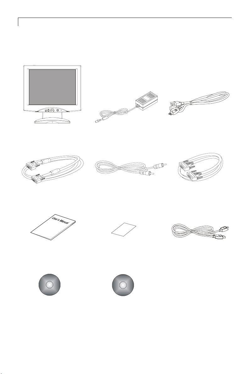
Package Overview
LCD Display
VGA Signal Cable
User’s Manual Quick Start Guide
Touchscreen Driver
Installation CD-ROM
Power Adapter
Audio-In Cable
Planar CD
Power Cord
RS-232 Series Cable
(for PT150M )
USB Cable
(for PT150MU)
Page 6
Installation
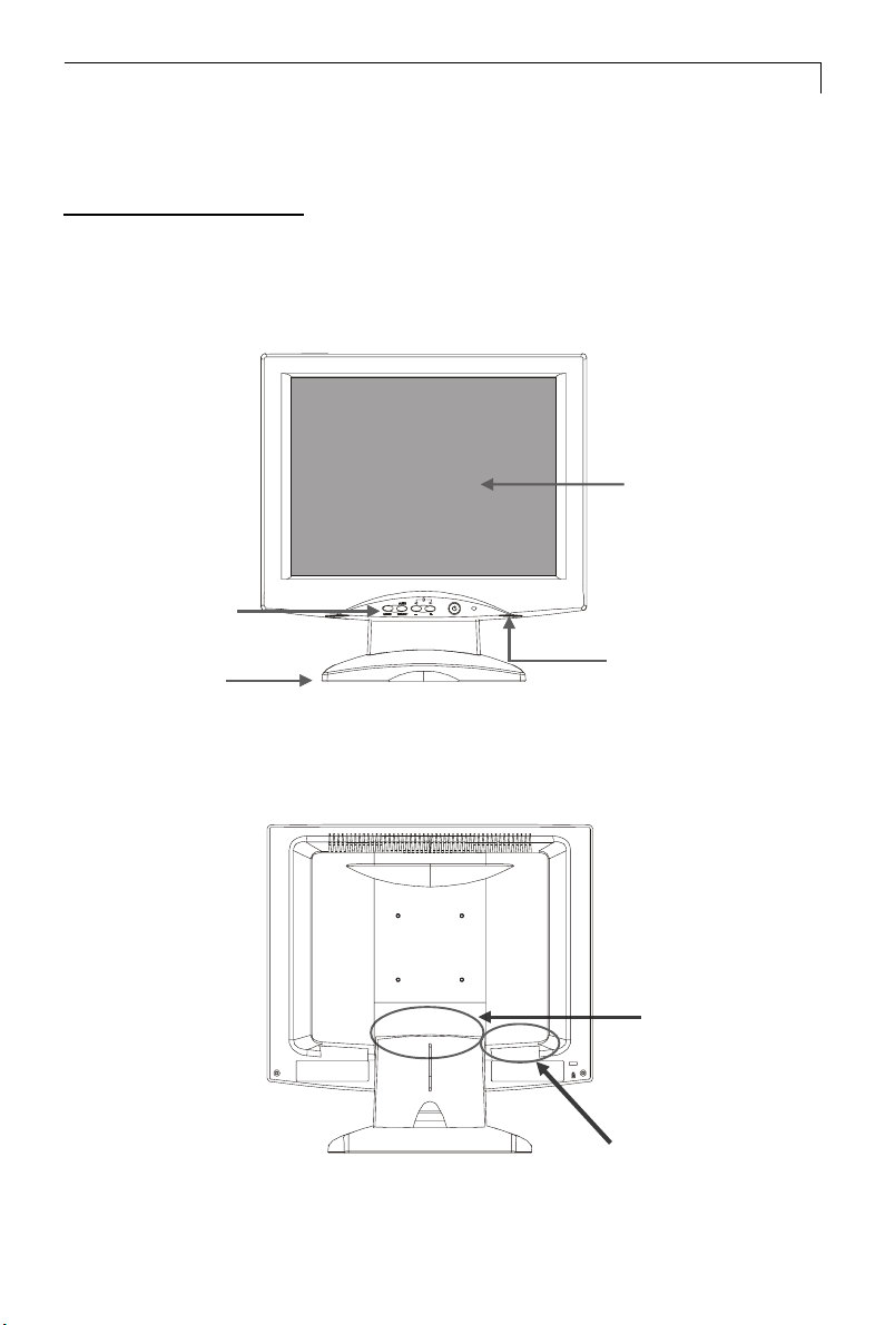
Product Overview
Front View
Panel
Controls
Stand
5
LCD Display
Speakers
Rear View
Connector Ports “A”
(Inside the back cover)
Connector
Ports “B”
Page 7
6
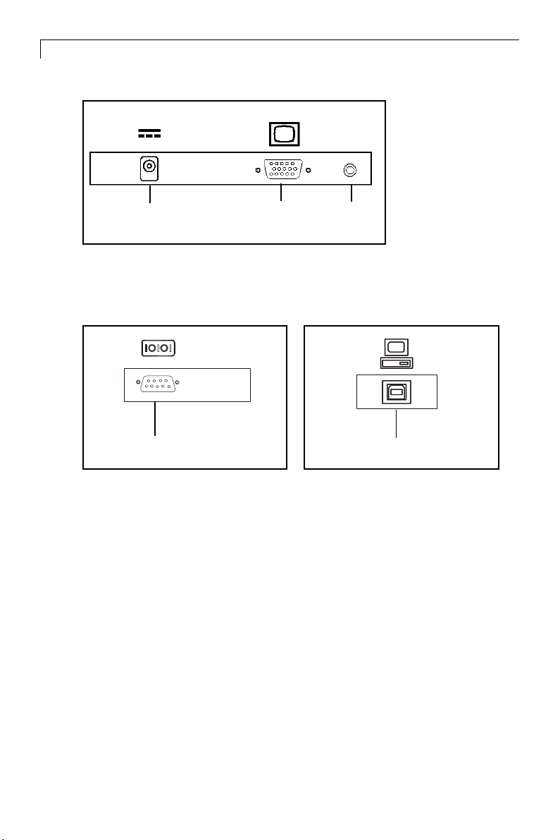
Connector Ports “A”
DC
Power-In
Connector Ports “B”
RS-232
(For PT150M)
Touch Function
VGA input
Audio
input
USB
(For PT150MU Touchscreen)
Page 8

Kensington Security Slot
The monitor can be secured to your desk or any other fixed object with
Kensington lock security products. Kensington lock is not included.
Kensington Security Slot
7
Page 9

8
VESA Mount your monitor
This monitor conforms to the VESA Flat Panel Mounting Physical Mount
ing Interface Standard which defines a physical mounting interface for flat
panel monitors, and corresponding standards for flat panel monitor mount
ing devices, such as wall and table arms.The VESA mounting interface is
located on the back of your monitor.
To mount the monitor on a swing arm or other mounting fixture, follow
the instruction included with the mounting fixture to be used.
Slots
75mm
VESA
Mounting
Interface
Note!
Please select the proper screws!
The depth from plastic back cover to the bottom of the screw hole is
8mm. The spec is M4 screw.
75mm
Page 10

Start Your Installation
Remove the Back Cover
Please follow these instructions to remove the cover on the back panel of the
LCD so that you can connect the cables in ”Connector Ports B.”
A
Back Cover
9
1. To remove the back cover, follow the arrows in Figure A and press with
both your thumbs. The cover should be removed by pressing firmly.
2. Follow the instruction on P.11 (Figure 11.1) to connect the cables in
”Connector Ports B.”
3. Fix the cover back to the LCD. You may also keep the cables in order
with the included cable organizer.
Included Cable
Organizer
Note: You can place the LCD flat horizontally to make it easier to
connect the cables. Please make sure that you place it on an even
surface lest the LCD should be damaged by scratches or collision.
Page 11

10
Connecting the Display (Figure 11.1)
To setup this display, please refer to the following figure and procedures.
1. Be sure the computer and monitor are turned off.
2. Connect the DC power cord to the power connector; plug one end of
the AC power cord into the poweradapter, and then the other end into an
electrical outlet().
3. Connect the VGA signal cable from display VGA input connector to the
15-pin connector of your host computer and tighten the screws().
4. Connect the Audio-In cable from audio input port of your display to the
Audio-out port of your computer().
5. Connect the RS-232 cable from RS-232 port of your display to the
RS-232 port of your computer().
6. Turn on your computer, display and video source.
Notice: To ensure the LCD display can work well with your computer,
please configure the display mode of your graphic card to make it
less than or equal to 1024 x 768 resolution and make sure timing
of the display mode is compatible with the LCD display.
We have listed the “Compatibility Modes” of this LCD display in
appendices for your reference.
Page 12

Figure 11.1
11
Audio-In
Cable
Power
Adapter
& Power
Cord
VGA
Cable
RS232
Cable
Page 13

12
User Controls
Front Panel Controls
AUTO
SELECT
MENU
No./ Icon Control Function
MENU Menu button Display the OSD menus
SELECT/AUTO Select/Auto Select- To select the adjustment items
from OSD menus.
Auto- To activate the “Auto Adjustment”
function to obtain an optimum image.
Power Switch Switches on/off the power of the LCD
Power LED 1.Green indicates the display is turned on.
3
4
Brightness Minus/ 1.Decreases the brightness of
Minus the display image.
2.Decreases value of the
adjustment items.
Brightness Plus/ 1.Increases the brightness of the
Plus display image.
2.Increases value of the
adjustment items.
display.
2. Amber indicates the display is in
power-saving mode.
Page 14

How to Use the OSD Menus
1. Press the “Menu” button to pop up the on-screen menu and to select
between the four Main Menus.
2. Choose the adjustment items by pressing the “Select/Auto” button.
3. Adjust the value of the adjustment items by pressing the “3” or “4”
button.
4. The OSD menu will automatically close, if you have left it idle for a
pre-set time.
13
Page 15

14
On-Screen Display Menus
First OSD Menu:
Auto-Adjustment
Contrast
Horizontal Position
Vertical Position
Frequency
Tracking
Main Menu
Page 1
No
Ye s
4 Auto-Adjustment
Choose this function to obtain an optimum image.
4 Contrast
This function allows you to adjust the image crispness. Contrast adjusts
the difference between white and black shades.
4 Horizontal Position
Changes the horizontal position of the image.
4 Vertical Position
Changes the vertical position of the image.
4 Frequency
Changes the display data frequency to match the frequency of your graphic
card. When you are experiencing vertical flickering bar, use this function to make
an adjustment.
4 Tracking
Synchronizes the signal timing of the display to that of the graphic card.
When you are experiencing unstable to flickering image, use this function
to make an adjustment.
Page 16

Second OSD Menu:
Main Menu
Page 2
Display Mode
OSD Off-Time
Language
Text-Graphic
Reset
1024* 768
FH: 60 kHz (+)
FV: 75 Hz (+)
4 Display Mode
The display mode shows the display resolution, horizontal scan frequency,
and vertical refresh of the current mode.
4 OSD Off-Time
Adjusts the time period for OSD menu to disappear.
4 Language
15
You are able to select the language of all menu items.
4 Text-Graphic
Toggles between VGA text mode (mode M03H) and graphic mode (mode M13H).
4 Reset
Returns the display parameters of the current mode to its factory default
settings.
Page 17

16
Third OSD Menu:
Main Menu
Page 3
Volume
Mute
-
0 20 40
4 Volume
It allows you to control the volume sound.
4 Mute
It allows you to disable the sound immediately.
+
Page 18

Fourth OSD Menu:
17
Main Menu
Page 4
Color Setting
Color Adjustment-Red
Color Adjustment-Green
Color Adjustment-Blue
9300K
6500K
Custom
4 Color Setting
Adjusts the color temperature.
4 Color Adjustment-Red
It allows you to adjust the red color of the display.
4 Color Adjustment-Green
It allows you to adjust the green color of the display.
4 Color Adjustment-Blue
It allows you to adjust the blue color of the display.
Preset
Page 19

18
Appendix
Troubleshooting
If you are experiencing trouble with the LCD display, refer to the
following. If the problem persists, please contact your local dealer or
our service center.
Problem: No image appears on screen.
Check that all the I/O and power connectors are correctly and
4
well connected as described in the “ Installation ” section.
4 Make sure the pins of the connectors are not crooked or broken.
Problem: Partial image or incorrectly displayed the image.
Check to see if the resolution of your computer is higher than that
4
of the LCD display.
4 Reconfigure the resolution of your computer to make it less than
or equal to 1024 x 768
Problem: Image has flickering vertical line bars.
Use “ Frequency ” to make an adjustment.
4
Check and reconfigure the display mode of the vertical refresh rate of your
4
graphic card to make it compatible with the LCD display.
Problem: Image is unstable and flickering
Use “ Tracking ” to make an adjustment.
4
Problem: Image is scrolling
Check and make sure the VGA signal cable (or adapter) is well connected.
4
Check and reconfigure the display mode of the vertical refresh rate of your
4
graphic card to make it compatible with the LCD display.
Problem: Vague image (characters and graphics)
Use “ Frequency ” to make an adjustment. If this problem still exists, use
4
“Tracking” to make an adjustment.
Page 20

Warning Signal
If you see warning messages on your LCD screen, this means that the
LCD display cannot receive a clean signal from the computer graphics
card.
There may be three sources for this problem. Please check
the cable connections or contact Planar for more information.
4 No Signal
This message means that the LCD display has been powered on but it cannot
receive any signal from the computer graphic card. Check all the power switches,
power cables, and VGA signal cable.
4 Going to Sleep
This message means that the LCD display is under the power saving mode. In
addition, the LCD display will go to this sleeping mode when experiencing a
sudden signal disconnecting problem.
19
4 Unsupport Mode
This message means that the signal of the computer graphic card is not compat
ible with the LCD display. When the signal is not included in the compatibility
mode we have listed in the Appendices of this manual, the LCD display will
appear this message.
Page 21

20
Product Dimensions
384.3mm/15.1”
382.5mm/15.06”
Front View
56.8mm/2.23”
Side View
Top View
180.1mm/7.1”
Page 22

Compatibility Modes
21
Mode
AGVMBI053x046075.13
AGVMBI004x046075.13
AGVMBI084x046065.13
AGVMBI004x027075.13
AGVASEV084x046279.73
AGVASEV084x046575.73
AGVSASEV006x008652.53
AGVSASEV006x008069.73
AGVSASEV006x008271.84
AGVSASEV006x008579.64
AGXASEV867x4201064.84
AGXASEV867x4201075.65
AGXASEV867x4201570.06
caMelppA084x046769.43
Resolution
V. Frequency
(Hz)
H. Frequency
(kHz)
caMelppA084x046760.53
caMelppA426x238577.94
caMelppA867x4201572.06
Page 23

11/2003
8am - 9pm Eastern Time
,
03/03
P/N:36.57709.002 Rev.A
 Loading...