

Page 1

PA1575R All-in-One
Touchscreen Computer
USER’S GUIDE
www.planartouch.com
Page 2

The information contained in this document is subject to change without notice.
This document contains proprietary information that is protected by copyright. All rights
are reserved. No part of this document may be reproduced,translated to another language
or stored in a retrieval system, or transmitted by any means, electronic, mechanical,
photocopying, recording, or otherwise, without prior written permission. Windows is a registered
trademark of Microsoft, Inc. Other brand or product names are trademarks of their respective
holders.
The test results show that this device meets the FCC rules. Those limits are set to protect
residential areas from the devices with harmful emission. This device will produce, use and
radiate radio frequency energy. In addition, failure to follow the user’s manual to install or use
this device might produce harmful interference with radio communication. Not withstanding
the foregoing, it does not guarantee that this type of harmful interference does not occur in
some special installations. The interference caused by this device to the reception of radio or
television signals may be verifi ed by turning it on and off. Any changes or modifi cations to this
TFT LCD would void the user’s authority to operate this device.
Important Recycle Instructions:
Lamp(s) inside this product contains mercury. This product may contain other
electronic waste that can be hazardous if not disposed of properly. Recycle or
dispose in accordance with local, state, or federal Laws. For more information,
contact the Electronic Industries Alliance at WWW.EIAE.ORG. For lamp specifi c
disposal information check WWW.LAMPRECYCLE.ORG.
For more information on how to recycle your product, please visit
WWW.PLANARSYSTEMS.COM/GREEN.
Page 3

Table of Contents
Usage Notice
Precautions .......................................................................................................................... 1
Introduction
About PA1575R .................................................................................................................... 2
Package Overview .......................................................................................................3
Installation
Product Overview ................................................................................................................. 4
Start Your Installation ............................................................................................................ 5
Kensington Security Slot ....................................................................................................... 6
VESA Mount For Your Computer .......................................................................................... 7
Remove the Deskstand .................................................................................................... 8
User Controls
Side Panel Controls .............................................................................................................. 9
Initial Turn-On ..................................................................................................................... 10
XP PRO Initial On Steps ................................................................................................. 10
Test Devices ....................................................................................................................... 17
Testing the Touchscreen ................................................................................................. 17
Recovering the Operating System ...................................................................................... 18
1.Using the Recovery CD ............................................................................................... 18
2.PA1575R Touchscreen Driver Install Instructions ........................................................ 26
Environmental Specifi cations .............................................................................................. 27
Touch Computer Specifi cations .......................................................................................... 28
Display Specifi cations ......................................................................................................... 29
Power Supply Specifi cations .............................................................................................. 29
Appendix
Troubleshooting .................................................................................................................. 33
Product Dimensions ............................................................................................................ 34
Compatibility Modes ........................................................................................................... 35
Product Registration and Technical Support .......................................................................36
Page 4

Usage Notice
cause electric shock
! Warning - To prevent the risk of fi re or shock hazards, do not expose
this product to rain or moisture.
! Warning - Please do not open or disassemble the product as this may
.
Precautions
Follow all warnings, precautions and maintenance as recommended in this user’s manual to
maximize the life of your unit.
Do:
• Turn off the product before cleaning.
• Touch screen surface may be cleaned using a soft clean cloth moistened with mild
window glass commercial cleaners or 50/50 mixture of water and isopropyl alcohol.
• Use a soft cloth moistened with mild detergent to clean the display housing.
• Use only high quality and safety approved AC/DC adapter.
• Disconnect the power plug from AC outlet if the product is not going to be used for
an extended period of time.
Don’t:
• Do not touch the LCD display screen surface with sharp or hard objects.
• Do not use abrasive cleaners, waxes or solvents for your cleaning.
• Do not operate the product under the following conditions:
- Extremely hot, cold or humid environment.
- Areas susceptible to excessive dust and dirt.
- Near any appliance generating a strong magnetic fi eld.
- In direct sunlight.
1
Page 5

Introduction
About PA1575R
The PA1575R Series is All-in-One Touch computer model, it has a 15" fl at panel screen
with an active matrix, thin-fi lm transistor (TFT) liquid crystal display (LCD). The TPC-152x
®
incorporates the Mobile Intel
945GSE Express Chipset with the ICH7M.
Features include:
• Intel Atom processor N270,1.6GHz, FSB 533MHz
• Onboard 10/100 BaseT and Gigabit LAN
• 7 ports, USB 2.0(Ext x 3, Int x 4)
• 2 x DB9 for COM1/COM2
• 1 x Digital displays(DVI-D)
• 1 x Line out
• 1 x 12V power jack
• 1024x768 XGA resolution
• 15" viewable display area
• Kensington security slot
• 75 mm VESA mount
• Touch function with USB interface
• Built-in speakers-1W x 2
Atom processor N270 at 1.6GHz, FSB533 and the Mobile Intel
Touch Screen for PA1575RXP
• Analog 5-wire resistive touch screen for fi nger and stylus input
• Surface: Anti-glare treatment
• Interface: USB controller
• Durability: 35 million touches at a single point
• Hardness of surface: 3H Typical
• Operating force: 40g~200g when using a silicon rubber tipped pen with a 1mm
diameter minimum and a hardness of 60 degree.
• Transmittance: 82%±5%
2
Page 6
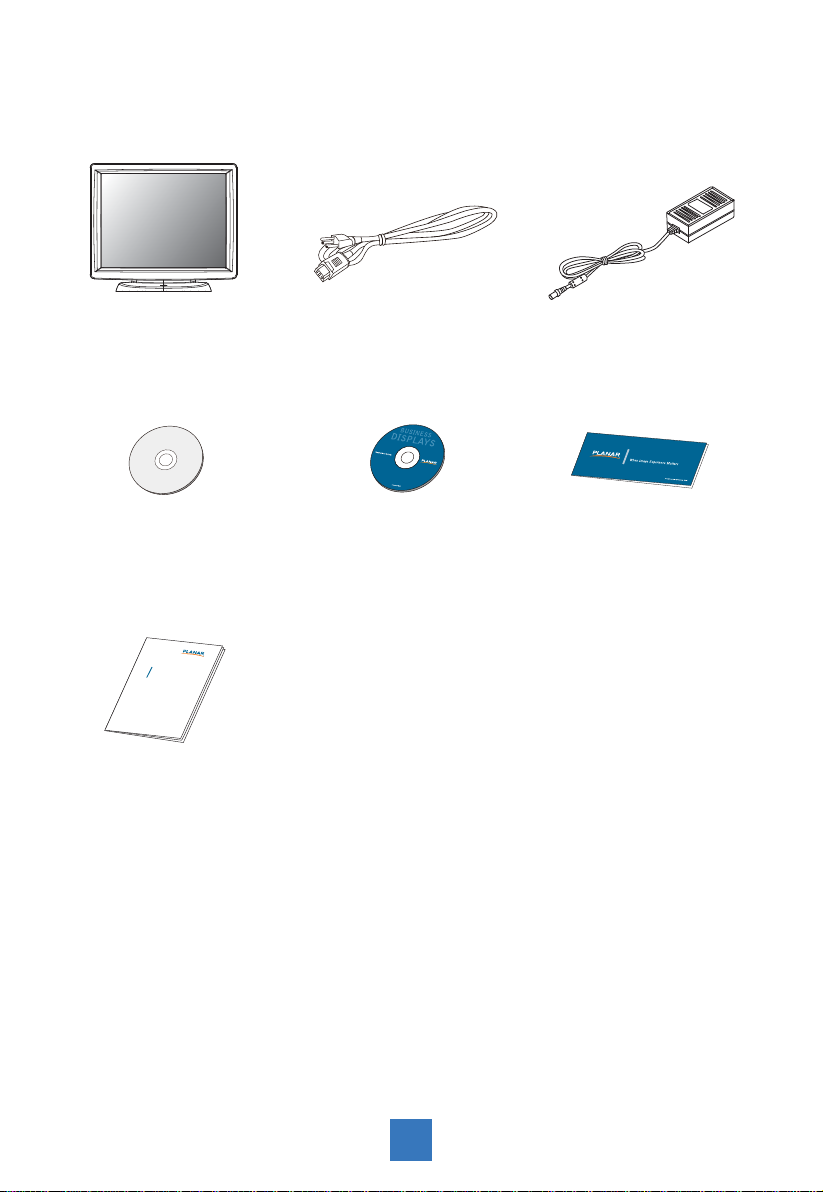
Package Overview
LCD Touch Computer
Power Cord
Recovery CD Touch Screen Driver
Installation CD-ROM
xxxxxxxxx
/
xxxxxxxxx
xxxxxxxxx
USER’S GUIDE
www.planartouch.com
User's Guide
DC Power Supply
Landing Strip
3
Page 7
Installation
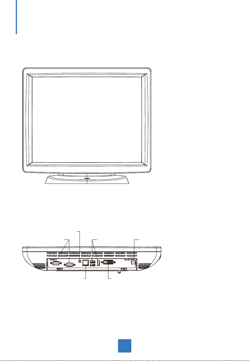
Product Overview
• Front View
• Button View (Without Stand)
AUDIO
RS-232
RJ-45 DVI
USB
DC IN
4
Page 8

Start Your Installation
Remove the Back Cover
Please follow these instructions to remove the cover on the back panel of the LCD so that
you can hookup the cables to associated connector.
Figure A
1. Remove the stand back cover by pulling in the direction of the arrow.
2. Connect applicable cables to the appropriate connectors.
3. Re-attach the stand back cover by pressing fi rmly until the tabs snap into place. You
may also keep the cables in order by using the cable organizer.
included cables organizer
!
Note!
You can place the LCD fl at horizontally to make it
easier to connect the cables. Please make sure
that you place it on an even surface lest the LCD
should be damaged by scratches or collision.
5
Page 9
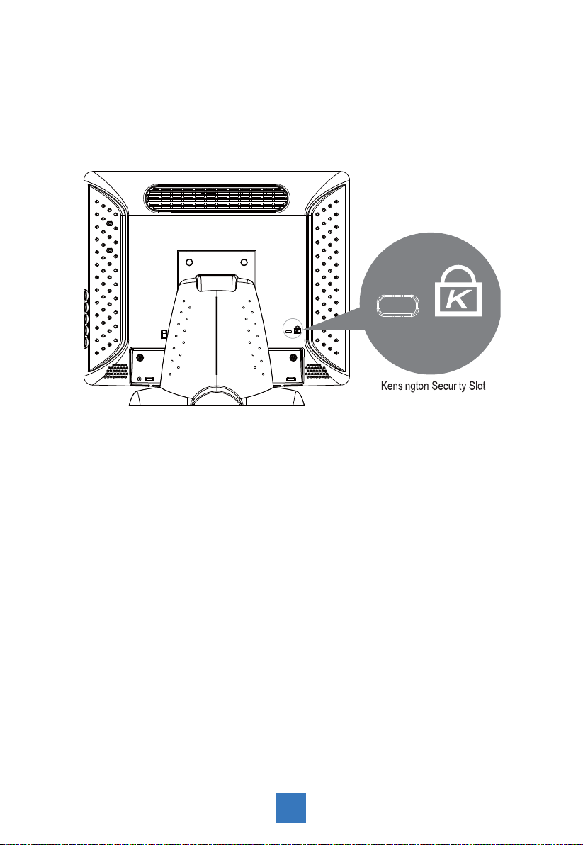
Kensington Security Slot
The computer can be secured to your desk or any other fi xed object with Kensington lock
security products. The Kensington lock is not included.
6
Page 10
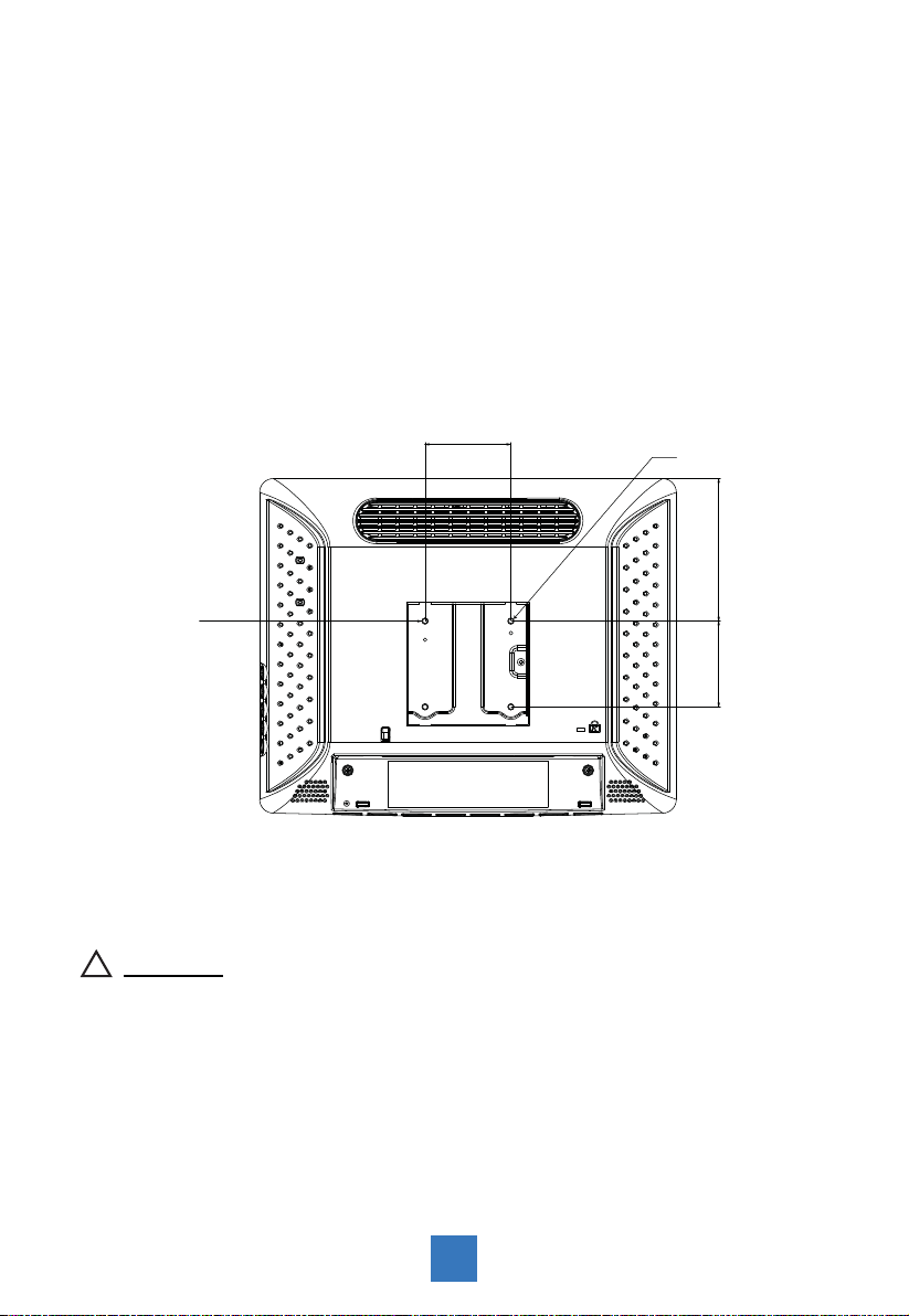
VESA Mount For Your Computer
This computer conforms to the VESA Flat Panel Mounting Physical Mounting Interface
Standard which defi nes a physical mounting interface for fl at panel computers, and
corresponding with the standard mounting devices of fl at panel computer, such as wall and
table arms. The VESA mounting interface is located on the back of touch computer.
To mount the computer on a swing arm or other mounting fi xture, follow the instructions
included with the mounting fi xture to be used, please note to mount touch computer to the
devices (either mounting fi xture or swing arm) what conforms to the UL listed.
!
Warning!
VESA
Mounting
Interface
75.0 mm
Slots ( x 4)
75.0 mm 124.5 mm
Please select the proper screws!
The distance between the back cover surface and the bottom of the screw hole
is 8 mm. Please use four M4 screws diameter with proper length to mount your
monitor.
Please note: the mounting stand must be able to support at least 11 lbs ( 5Kg).
7
Page 11
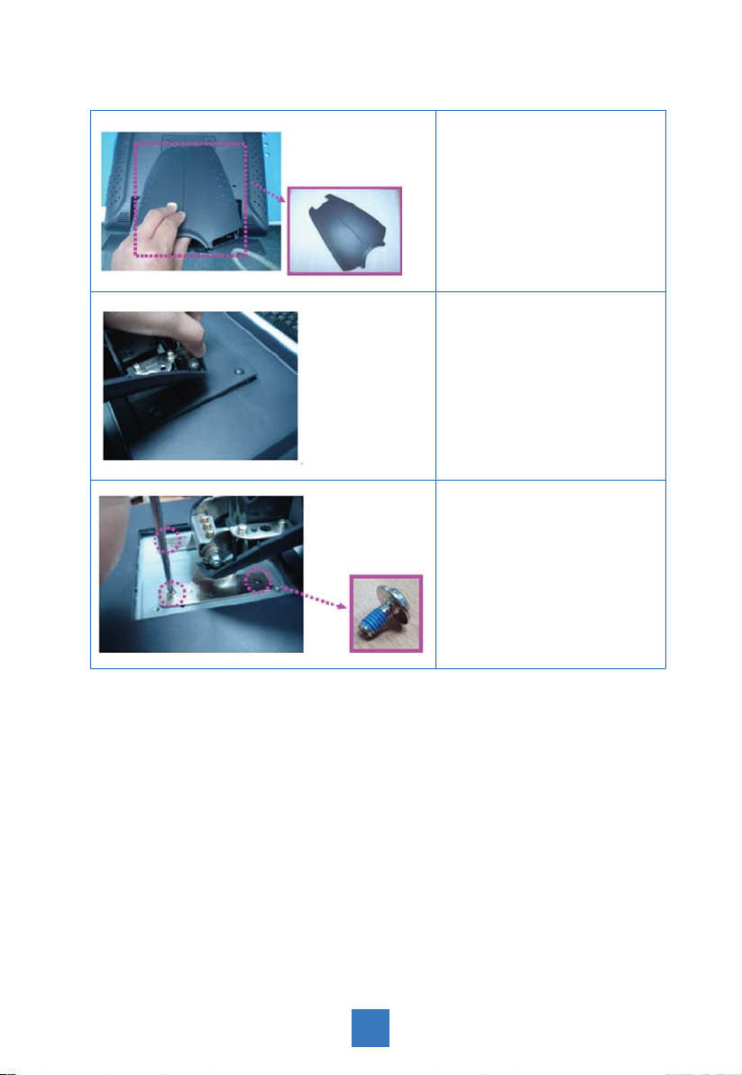
Remove the Deskstand
Remove stand back cover.1.
Remove hinge cover.2.
Remove 4 screws and then 3.
remove hinge.
8
Page 12
User Controls
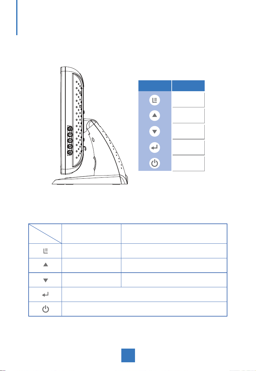
Side Panel Controls
Icon Key Name
Menu
Up
Down
Enter
Power
OSD
Key
Menu off status Menu on status
Menu appear Menu disappear / return to main item
Brightness Main item select up / Adjust up
Mute Main item select down / Adjust down
Enter/Select sub-item function
Power On/Off
9
Page 13

Initial Turn-On
The initial setup of the operating system takes approximately 5-10 minutes. Additional
time may be needed depending on touch computer hardware confi guration and connected
devices. To setup the Windows OS for the touch computer, turn on the touch computer and
follow the instructions on the screen.
XP PRO Initial On Steps
Step 1. Boot Computer
▎
▼
▎
▼
10
Page 14

Step 2. Press "Next"
Step 3. Read agreement and press " I accept this agreement" and
"Next".
11
Page 15

Step 4. Language Selection, Press "Next"
Click Customize. The Regional and Language window shown below will appear.
Step 5. Type your full name, organization and press "Next"
12
Page 16

Step 6. Type product key and press "Next"
Please fi nd the "Certifi cate of Authenticity" license label on the back-cover.
13
Page 17

Step 7. Setup your computer name, administrator password and
press "Next"
Step 8. Date and Time Settings, Setup your computer date and
time and press "Next"
14
Page 18

Step 9. Choose typical or custom setting and press "Next"
Step 10. Choose applicable option
▎
▼
15
Page 19

Step 11. Press "Finish"
Step 12. Finish and launch windows system
16
Page 20

Test Devices
The touch computer can be pre-installed with several different hardware options. To test an
optional device that is installed on the touch computer, follow the instructions below.
NOTE: Testing icons are located on the desktop. Testing of a particular device can only be
done after the device is properly installed.
Testing the Touchscreen
The touchscreen is pre-calibrated for accurate touch response.
Calibration* If for any reason the touchscreen needs to be re-calibrated, double-click the Touchscreen-test
icon. The window shown below will open.
→→
17
Page 21

Recovering the Operating System
If the touch computer’s operating system and software needs to be recovered, insert the
included recovery disk into an external DVD-ROM (sold separately) and reboot the touch
computer. Follow the on-screen instructions to complete recovery.
NOTE: All data will be deleted during the recovery process. User must back up fi les prior to
recovering the operating system.
1. Using the Recovery CD For XP Pro
To recover your pre-installed software using the recovery CD, do as follows:
Step 1.
Step 2.
Step 3.
From the Start menu, restart your computer.
Insert "Recovery CD" in CD-ROM to begin sequence.
Press any key to boot from CD
▼
18
▎
Page 22

▼
▎
Step 4.
Press any key to continue
▼
▎
19
Page 23

Step 5.
Press any key to continue
▼
▎
▼
20
▎
Page 24

Step 6.
Press "Next"
Step 7.
Read agreement and press "I accept this agreement" and "Next".
21
Page 25

Step 8.
Press "Next"
Step 9.
Type your full name, organization and press "Next"
22
Page 26

Step 10.
Please fi nd the "Certifi cate of Authenticity" license label on the back-cover.
Type product key and press "Next"
23
Page 27

Step 11.
Setup your computer name, administrator password and press "Next"
Step 12.
Step 13.
Setup your computer date and time and press "Next"
Choose typical or custom setting and press "Next"
24
Page 28

Step 14.
Choose applicable option
Step 15.
Step 16.
Press "Finish"
Finish and launch windows system
25
Page 29

2. PA1575R Touchscreen Driver Install Instructions:
The touch driver is located on the enclosed CD-ROM for these operating systems:
Windows® XP
Step 1.
separately)
Step 2.
Step 3.
Step 4.
Insert the included Touchscreen disk into an external DVD-ROM (sold
Select the monitor size 15” and then model name PA1575R.
Click on the “Load Driver” button that appears to the right of the model name.
Follow the step-by-step instructions as shown on the pop-up windows.
26
Page 30

Environmental Specifi cations
Temperature Ranges
Operating Temperature (Independent of altitude) 0oC to 35oC
Non-Operating Temperature (Independent of altitude) -20
Humidity
Operating (non-condensing) 20% to 80%
o
Non-Operating (38.7
Altitude Ranges
Operating
C maximum wet bulb temperature) 10% to 90%
0 to + 12,000 feet [3,658m].
Equivalent to 14.7 to 10.1 psia.
o
C to 60oC
Non-Operating
0 to + 40,000 feet [12,192m].
Equivalent to 14.7 to 4.4 psia.
27
Page 31

Touch Computer Specifi cations
Processor Intel ATOM processor N270 w/533MHz FSB
RAM 2GB DDR2 RAM
Northbridge Intel 945GSE
Southbridge Intel ICH7-M
Video Intel GMA 950
Operating systems Microsoft Windows XP Professional Embedded
7 x USB 2.0 ports (Ext. x 3, Int x 4)
1 x 10/100 BaseT and Gigabit LAN
Ports
2 x Serial ports (DB9) COM1, COM2
1 x line-out 3.5mm
1 x DVI-D
12V Power Jack
BIOS Intel BIOS
Replaceable lithium-ion battery for clock
Real Time clock
Storage XP: SATA 2.5'' HDD 160GB (or above)
Power supply
Temperature
Humidity Operating:
Weight
Backlight lamp life Min 40,000 hours to half brightness
Agency approvals UL/cUL, FCC, CE, TUV, EN60950
Speakers (internal) 1W speakers
Mounting options 75 mm VESA mount
Caution: Risk of Explosion if Battery is replaced
by an Incorrect Type. Dispose of Used Batteries
According to the Instructions.
Type: External brick
Input (line) voltage: 100-240 VAC, 50-60 Hz
Output voltage/current: 12 V at 4.16 amps
Operating: 0
Storage: -20
Operating: 20%-80%
Storage: 10%-90%
noncondensing
Actual: 17.2 lb (6.0 kg)
Shipping: 22.5 lb (8.93 kg)
Shipping box dimensions 465 x 375x 288
Support ACPI SMBIOS
o
C to 35oC
o
C to 60oC
28
Page 32

Display Specifi cations
Model PA1575RXP
LCD Display 15" TFT Active Matrix Panel
Display Size 304.1(H) x 228.1(V) mm
Pixel Pitch 0.297(H) x 0.297(V) mm
Native XGA 1024 x 768
Display Color 16.2 million color
Plug & Play DDC 2B
Power Supply Specifi cations
The touch computer shall be powered by 12VDC from a universal type power supply brick
with the following characteristics:
Input voltage 100 to 240 V~
Input frequency 50/60 Hz
Output voltage 12 V
Output line and load regulation +/- 5%
Output current 4.1 Amps Rated
29
Page 33

Removable base
Other features
Peripheral Options and Upgrades
Fanless
Touchscreen sealed to bezel and LCD
Security lock receptacle
May vary
Battery Notice Caution:
Risk of explosion if battery is replaced by an incorrect type.
Dispose of used batteries according to the instructions.
COM1, COM2, Connector(RS232 Mode)
Pin # Signal Name
shell Ground
1 DCD
2 RXD
1
6
3 TXD
4 DTR
5 signal ground
6 DSR
7 RTS
8 CTS
9 RI
30
Page 34

RJ45 LAN connector Pin Defi nition
Pin # Signal Name
1 TD+
2 TD-
8 1
3 RD+
6 RD-
Power Input Pin Defi nition
Pin # Signal Name
1
1 +12V
2
2 Ground
USB Pin Defi nition
Pin # Signal Name
1234
1 +5V
2 USB D-
3 USB D+
4 GND
31
Page 35

DVI-D Pin Defi nition
Pin # Signal Name
1 DATA 2-
2 DATA 2+
3 Shield 2/4
4 DATA 4-
5 DATA 4+
6 DDC CLOCK
7 DDC DATA
8 VSYNC
18
17924
9 DATA 1-
10 DATA 1+
11 SHIELD 1/3
12 DATA 3-
13 DATA 3+
14 DDC POWER
15 A GROUND 1
16 HOT POWER
17 DATA 0-
18 DATA 0+
19 SHIELD 0/5
20 DATA 5-
21 DATA 5+
22 SHIELD CLK
23 CLOCK -
24 CLOCK +
32
Page 36

Appendix
Troubleshooting
If you are experiencing trouble with the LCD display, refer to the following. If the problem
persists, please contact your local dealer or our service center.
Problem: No image appears on screen.
► Check that all the I/O and power connectors are correctly and well connected
described in the "Installation" section.
► Make sure the pins of the connectors are not crooked or broken.
Problem: Partial Image or incorrectly displayed image.
► Check to see if the resolution of your computer is higher than that of the LCD
display.
► Reconfi gure the resolution of your computer to make it less than or equal to
1024 x 768.
33
Page 37

Product Dimensions
► Front View
► Side View
364.0 mm
69.0 mm
240.0 mm
176.3 mm
295.0 mm
321.9 mm
► Top View
206.1 mm
34
Page 38

Compatibility Modes
Mode Resolution H-Frequency (KHz) V-Frequency (Hz)
VGA 720 x 400 31.47 70
VGA 640 x 480 31.47 60
VESA 800 x 600 37.88 60
VESA 1024 x 768 48.36 60
35
Page 39

Product Registration and Technical Support
Register Your Planar Products Today
Thank you for choosing Planar. To assure you receive all the benefi ts of your Planar product
and services, register your Planar product today. Visit our website to register your product at
http://www.planar.com/support/product_registration.html.
Cables, Replacement Lamps, Accessories
To fi nd cables, replacement lamps and accessories for your Planar projector, LCD monitor,
touch screen or other Planar products visit our online store at www.PlanarOnline.com or
fi nd other stores who carry Planar products at http://www.planar.com/howtobuy.
Technical Support
Visit Planar at http://www.planar.com/support for product registration, operations manuals,
touch screen drivers, warranty information and access to Planar’s Technical Library for online
troubleshooting.
To speak with Planar Customer Support please have you model and serial number available
and dial:
Planar Support
Tel: 1-866-PLANAR1 (866-752-6271) or +1 503-748-5799 outside the US.
Hours: 24 hours a day, 7 days a week.
Toll or long distance charges may apply.
36
Page 40

Planar Systems, Inc.
Customer Service
24x7 Online Technical Support: http://www.planar.com/support
1195 NW Compton Drive
Beaverton, OR 97006-1992
Tel: 1-866-PLANAR1 (866-752-6271) or +1 503-748-5799 outside the United States.
Hours: 24 hours a day, 7 days a week
© 2011 Planar Systems, Inc. 5/11 Planar is a registered trademark of Planar Systems, Inc.
Other brands and names are the property of their respective owners.
Technical information in this document is subject to change without notice.
020-1025-00D
820450085101
 Loading...