

Page 1
Dome EX Displays
MX2/MX3 Display Controller
Reference Guide
Windows XP
Windows 2000
020-0491-00A_1.indd 1020-0491-00A_1.indd 1 8/22/06 5:18:04 PM8/22/06 5:18:04 PM
Page 2
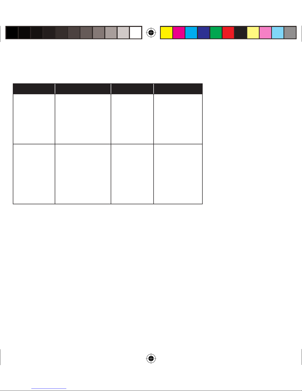
Before You Begin
Check that your system meets these requirements for installation of
a Dome EX display system.
EX Display Controller System Requirements Operating System
Dome E2 MX2 • PCI slot (64-bit recommended)
• 50 MB hard disk space
• 256 MB RAM
Dome E3 MX3
• CD-ROM drive
• Power supply, 350 watts or greater
• .NET Framework 1.1
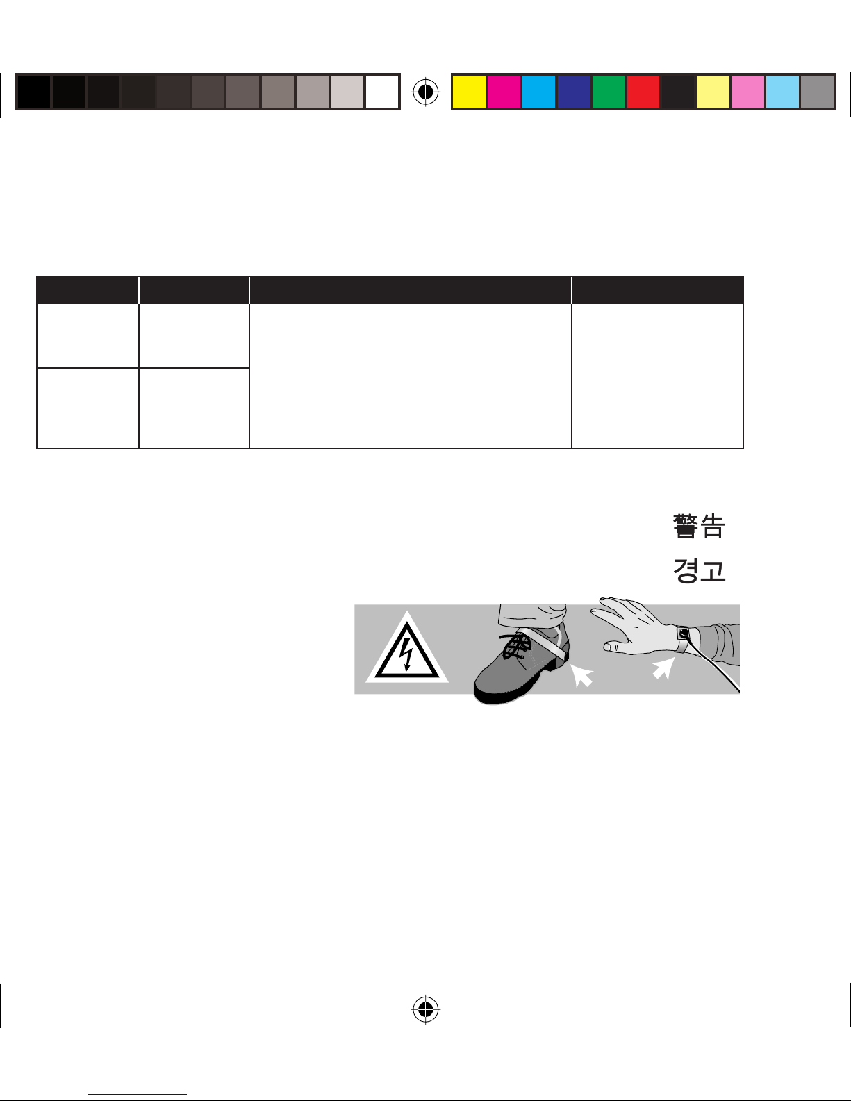
Safety Precaution
Wear an antistatic heel or wrist
strap when installing the video
card to avoid damage to
computer components.
Warning
Avertissement
Avvertenza
Windows XP
Service Pack 1 or
Windows 2000
Service Pack 4
Advertencia
Warnung
2
020-0491-00A_1.indd 2020-0491-00A_1.indd 2 8/22/06 5:18:07 PM8/22/06 5:18:07 PM
Page 3
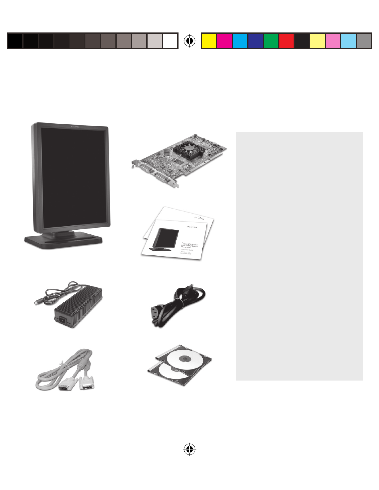
Unpacking the Display
Check the contents of your Dome EX display package for all the items
shown here. Save the original packaging materials for storage and shipping.
Guidelines
• Use both hands to lift
or adjust the display.
• Avoid touching the
Dome EX
digital at panel
Power block
Display controller
Dome EX and Dome CXtra
quick references
Power cord
display screen.
• Do not set up the display
in areas with sudden
temperature changes and
strong light sources.
• Do not block the vents on
the back of the display.
• Do not remove the back
cover or disassemble
the display.
• In locations where 240V
outlets are used, connect
the display only to a
center-tapped, 240V,
single-phase supply.
Dome display driver
DVI-to-DVI video cable
020-0491-00A_1.indd 3020-0491-00A_1.indd 3 8/22/06 5:18:07 PM8/22/06 5:18:07 PM
and Dome CXtra CDs
3
Page 4
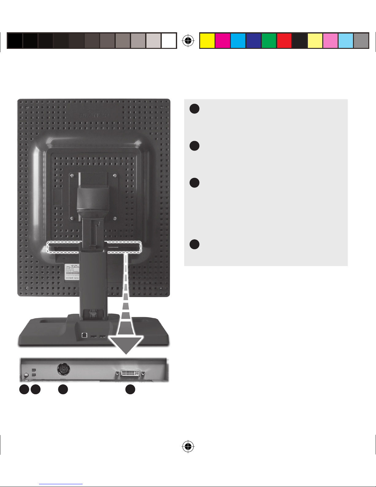
Display Components
Reset button.
1
Restores the display con guration
to its default setting.
LED status lights.
2
Provides information about the
status of the display.
3
DIN connector.
Drives power to the display;
4-pin connector on the Dome E2
display, 8-pin connector on the
Dome E3 display.
DVI connector.
4
Drives the data to the display.
1 2 3 4
4
020-0491-00A_1.indd 4020-0491-00A_1.indd 4 8/22/06 5:18:08 PM8/22/06 5:18:08 PM
Page 5

Installing the Display Controller
See safety precautions on page 2. Remove any existing graphics
card and its driver from your computer system before you install the
MX2 or MX3 board and driver. Also disable any onboard graphics capability
on the motherboard.
To install the controller
1 Turn o your computer and all
peripherals. Disconnect all cables
from your computer. Leave the power
cord plugged into the grounded outlet.
2 Remove the computer cover.
3 Remove the blank bracket from the
available PCI slot.
4 Insert the controller into the slot, align
the connector pins, and press the board
down until it is rmly seated.
5 Secure the mounting bracket.
6 Reattach the computer cover and the
peripherals.
When installing multiple display
controllers, install all of them before
you install the driver.
Open PCI slot
Blank bracket
MX2 or MX3 board installed
020-0491-00A_1.indd 5020-0491-00A_1.indd 5 8/22/06 5:18:09 PM8/22/06 5:18:09 PM
5
Page 6

Connecting the Display
Use only the cable and power cord supplied with the Dome EX display.
To connect the display
1 Plug one end of the DVI cable into
the DVI connector port. Tighten the
thumbscrews to secure the connection.
2 Plug the power cord into the power
input port.
3 Plug the other end of the DVI cable into
the video port on the installed display
controller. Use DVI port #1 (the bottom
port) to install the rst or only display.
4 Plug the other end of the power cord
into a grounded outlet.
Power cord DVI cable
5 Power on your display rst, then
the computer.
Connection for
a single display
DVI
port 1
DVI cable
MX2 or MX3
board installed
6
020-0491-00A_1.indd 6020-0491-00A_1.indd 6 8/22/06 5:18:09 PM8/22/06 5:18:09 PM
Page 7

Installing the Display Driver
Before you install the driver, remove any previously installed display driver for
the controller from your system.
To install the driver
1 Start your computer system. Log on with administrator privileges.
2 Click Cancel on the Found New Hardware Wizard. Click No at the restart prompt.
3 Insert the driver installation CD and click Next. Auto-detection reports the
driver version and controller board(s). Click Next.
4 Click the check box to enable independent mode for each controller.
Click Next.
5 Click Next to continue. File copy begins.
6 Click Continue Anyway on the dialog reporting no digital signature.
Repeat for a second controller.
7 Click Next upon completion of the driver installation.
8 Select the Restart computer option and click Finish.
To con gure the display
1 Right-click the desktop and select Properties > Settings.
2 Use the native resolution of the display.
3 For use of the second display, select Extend my Windows desktop onto
this monitor.
4 Click OK until you return to the desktop.
7
020-0491-00A_1.indd 7020-0491-00A_1.indd 7 8/22/06 5:18:10 PM8/22/06 5:18:10 PM
Page 8

Adjusting Display Properties
To set brightness
You must have the Dome CXtra software installed to change the display
brightness. Adjust the value of the white level on the Backlight tab of the
RightLight Panel Con guration.
To rotate the display
1 Click the PowerDesk icon on the taskbar.
2 Select Monitor Adjustments on the PowerDesk menu.
3 Select Adjust Orientation.
4 Select the degree of rotation.
5 Click OK.
To set up multi-display mode
1 Click the PowerDesk icon on the taskbar.
2 Select Multi-Display Setup on the PowerDesk menu.
3 Select the device and multi-display setup you want to use.
4 Click OK.
8
020-0491-00A_1.indd 8020-0491-00A_1.indd 8 8/22/06 5:18:10 PM8/22/06 5:18:10 PM
Page 9

To change video setting per display
1 Click the PowerDesk icon on the taskbar.
2 On the PowerDesk menu, select the controller representing the display you
want to change video settings on, then select Grayscale Setup category.
NOTE: Grayscale mode is the installation default.
3 Select the grayscale option and the xed linear gray palette.
4 Click OK.
5 Restart the system.
NOTE: You must restart the system each time you change the video settings of a
display. For dual con gurations, change the settings of the rst display and restart
the system, then change the settings of the second display and restart.
Click Help on the PowerDesk menu for more information.
020-0491-00A_1.indd 9020-0491-00A_1.indd 9 8/22/06 5:18:10 PM8/22/06 5:18:10 PM
9
Page 10
Display Resolutions and Palette Options
Display Resolution Palette Bits per pixel
Dome E2 1200 x 1600
1600 x 1200
1200 x 1600
1600 x 1200
Dome E3 1536 x 2048
2048 x 1536
1536 x 2048
2048 x 1536
Grayscale
True color
Grayscale
True color
8
32
8
32
10
020-0491-00A_1.indd 10020-0491-00A_1.indd 10 8/22/06 5:18:10 PM8/22/06 5:18:10 PM
Page 11

Cleaning the LCD Screen
Use a dry, clean, lint-free cotton cloth to remove
surface dust from the display screen. Do not use
chemically treated dust cloths.
To remove grease or organic contaminants, follow
this procedure:
1 Disconnect the power supply from the display.
2 Dampen a soft, clean cloth with a small amount of
isopropyl alcohol.
3 Wipe the display screen gently with the
dampened cloth.
4 Use a dry, clean, lint-free cotton cloth to wipe o
the residue.
Do not spray or use
acetone, toluene, or
harsh solvents on the
display case or screen.
Chemical cleansers
may cause damage
to the display.
020-0491-00A_1.indd 11020-0491-00A_1.indd 11 8/22/06 5:18:10 PM8/22/06 5:18:10 PM
Do not touch the
LCD screen with your
ngers. Skin oils are
hard to remove from
the screen.
Do not saturate the
cleaning cloth. Liquid
that drips on the glass
may seep into the
display case.
11
Page 12
America Sales
Planar Systems, Inc.
1195 NW Compton Drive
Beaverton, OR 97006-1992 USA
(503) 748-1100 phone
(503) 748-1493 fax
Medical Sales
Planar Systems, Inc.
400 Fifth Avenue
Waltham, MA 02451-8738 USA
(781) 895-1155 phone
(781) 895-1133 fax
Customer Support
Visit www.planar.com
E-mail: medicalsupport@planar.com
Call (866) PLANAR1
Europe Sales
European Representative
Planar Systems, Inc.
Olarinluoma 9, P. O. Box 46
FIN-02201 Espoo, Finland
+ 358 9 420 01 phone
+ 358 9 420 0200 fax
vertrieb@planar.com
medicalsupport@planar.com
www.planar.com
Asia-Pacifi c Sales
Planar Systems, Inc.
388 Nan Jing West Road, Suite 3905
Shanghai Peoples Republic of China
+ 86 21 6334 5050 phone
+ 86 21 6334 6339 fax
sales@planar.com.cn
support@planar.com.cn
www.planar.com.cn
Copyright © 2006 Planar Systems, Inc. Planar is a registered trademark of Planar Systems, Inc.
Technical information in this document is subject to change without notice.
020-0491-00A
020-0491-00A_1.indd 12020-0491-00A_1.indd 12 8/22/06 5:18:11 PM8/22/06 5:18:11 PM
 Loading...