

Page 1
m52L Quick Start Guide
This guide walks you through the basic setup needed to get
your new Planar displays up and running. Detailed information
is contained in the Installation Guide, which is in a CD-ROM on
the back of this guide.
Planar Systems, Inc.
1195 NW Compton Drive
Beaverton, OR 97006-1992
Phone: +1 503 748 1100
Toll-free Phone: +1-866-475-2627
Fax: +1 503 748 5532
www.planar.com
Technical Support:
Phone: +1 503 748 5799
Toll-free Phone: +1-866-PLANAR1 (752-6271)
Email: planarsupport@planar.com
Contents
Product/Safety Information
1
Unpacking the Display
2
Installing the VIM
3
Installing Screen Brackets
4
Connecting Source Cables
5
Connecting Power, Turning It On/Off
6
Using the Remote and Menus
7
Selecting a Source
8
Adjusting Levels for Analog Sources
9
Adjusting Input Levels and Position
10
Color Balancing for One Display
11
Color Balancing for Multiple Displays
12
Recommended Usage
13
Declaration of Conformity
14
020-0910-00A
Downloaded From TV-Manual.com Manuals
Page 2
Product and Safety Information
Planar
Landscape
Port rait
Planar
The m52L is a 52” diagonal direct-view LCD monitor that can
be wall-mounted, ceiling mounted or mounted on a stand.
The display can be portrait or landscape. Mounting should be
done so the logo is as shown.
The m52L is 5" deep. It has an aspect ratio of 1.77 (16:9). It
accepts a wide range of input pictures from VGA to 1080p.
With the optional Video Input Module, the m52L accepts
NTSC and PAL as composite, component, S-Video or SDI. The
m52L also accepts composite SECAM and component VGA to
1080p video inputs through the analog connection, as well as
HD-SDI input (1080i, 720p).
VESA Mounts
A variety of VESA mounts used to secure the m52L are available through Planar. If you purchased a VESA mount, you
should have received a separate box with mounting supplies
and an Installation manual. Follow these instructions carefully. Keep the following in mind:
• Screw length is crucial and will vary depending on the type of
mount you use.
• Identify where all of the mounting points are located.
• Verify the parts received with the list shown in the VESA Installation manual.
Safety Precautions
Although the m52L was designed with safety in mind, please
review the following warnings and cautions.
WARNING! Wall mounts must be secure.
If the display is hung on a wall, the wall must be strong
enough to hold it. The m52L weighs about 86lbs (39kg).
Mounting a display to wallboard or wall paneling won’t be
adequate or safe. The mounting method must be capable of
holding five times this weight, 430lbs (195kg).
Caution: The screen could be damaged by heavy pressure.
Slight pressure on the LCD will cause image distortion. Heavy
pressure will cause permanent damage. Mount displays
where viewers cannot touch the screen.
Caution: The front polarizer is soft and subject to scratches from
sharp objects.
The polarizer is a thin sheet of film laminated to the outside
layer of glass on the LCD screen. Take care when handling
items near the screen.
WARNING! The backlight contains mercury.
Lamp(s) inside this product contain mercury. This
product may contain other electronic waste that can
be hazardous if not disposed of properly. Recycle or
dispose in accordance with local, state, or federal Laws. For
more information, contact the Electronic Industries Alliance
at www.eiae.org
check www.lamprecycle.org
. For lamp specific disposal information,
.
Downloaded From TV-Manual.com Manuals
Page 3
Unpacking the Display
2
Unpacking the
Display
Planning
Before you unpack your displays, you should have a detailed
plan of how the displays are to be configured. It should include
the following calculations:
•Power (max. of three units per 20A circuit for 115V operation)
•Cable runs
• Ventilation and cooling requirements
• If hanging display on a wall, location of studs in the wall
Have the Following Tools Available:
• Level to ensure the display is hung straight.
• Stud finder (if hanging display on a wall).
• Computer network LAN cables (straight through - no crossover)
to interconnect multiple displays for RS232 control.
• LCD screen cleaner or LCD wipes, available at most electronics
stores.
• Although a VGA cable is included with every display, you may
wish to obtain a long-run VGA, SDI or DVI cable if your source is
located far away from the display(s).
• Needle nose pliers to remove staples from the bottom of the
shipping box.
• Utility knife to open box and display packaging.
• At least two very strong people to help lift displays into place. If
possible, more than two people are recommended.
Unpacking the Display
1 Using a utility knife, open a display’s box.
2 Using at least two people, carefully remove the display
from the box.
3 Remove the display from its shipping pouch.
4 Install power and source cables.
5 If you are tiling a video wall, install brackets on each dis-
play before you set up the wall.
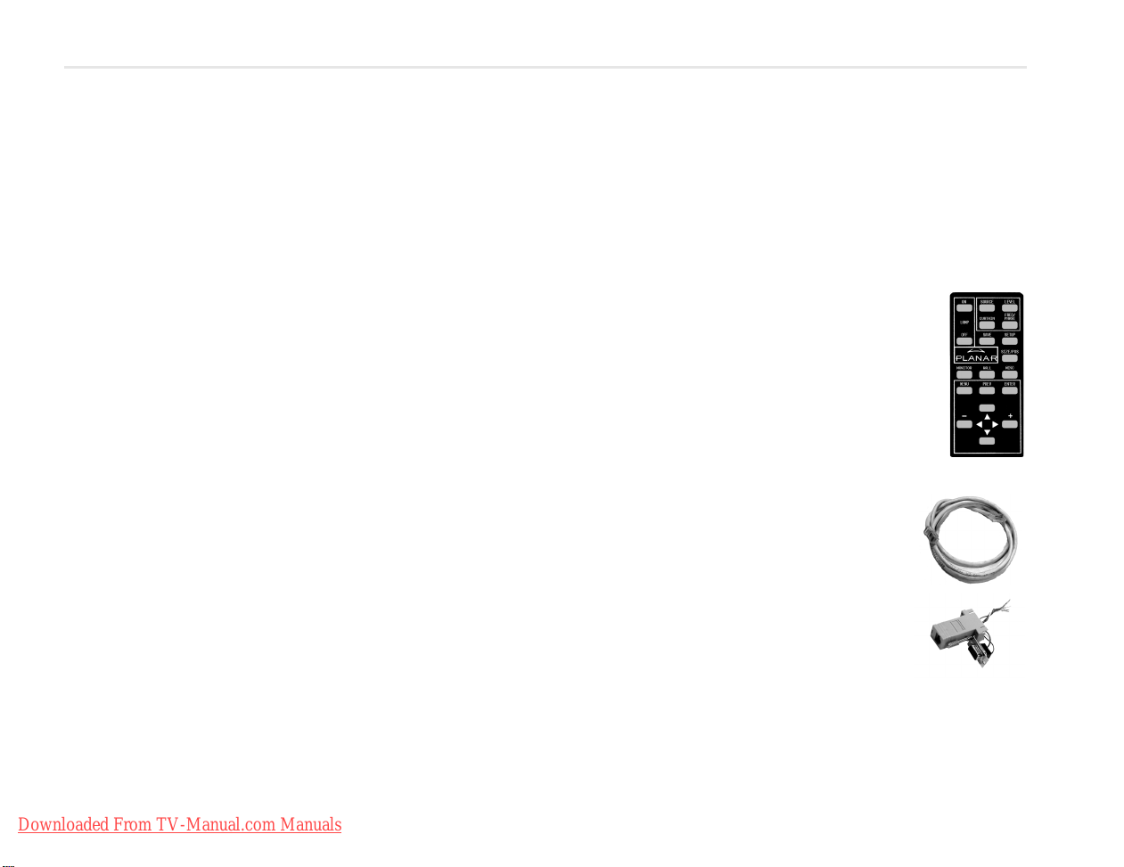
Checking Accessories
Check for the following items included in your accessory box:
• This guide and the Installation Guide CD on the back of this
guide
• Remote control (with the batteries already
installed)
• Power cord (for use in North America)
• 15-pin cable for analog computer pictures
(although it’s called VGA, it carries anything up to
UXGA)
• Brackets and couplers for video wall installation
• DVI-D cable for use with the monitor
Make sure you have the following customer-supplied items as needed to complete your installation:
• RJ45 to 9-pin adapter, if you will use RS232
commands to control the display
• RJ45 cable, computer network type
• Component video cables
• S-video cables
•SDI cables
• RS232 cable
Downloaded From TV-Manual.com Manuals
Page 4
Installing the Video Input Module (VIM)
Installing the VIM
3
If you receive the optional Video Input Module (VIM) separately,
use the following instructions to install it. Your VIM shipment
should include the following items: VIM board, new VIM cover,
mounting screws, washers/nuts and a ground strap.
1 Attach the ground strap to your wrist and the chassis.
2 Turn off the AC power and unplug all cables.
WARNING! Always turn off power and remove the power cord when
adding or removing an electronic part.
3 Remove the screws that secure
the old VIM cover. Place the
screws aside.
4 Remove the old VIM cover.
WARNING! Failure to properly use a
grounding strap can destroy sensitive
electronic components in the VIM board.
5 Remove the VIM board from its
shipping pouch and anti-static
bag.
6 Install the VIM board in its place, pressing the VIM board
connector into the control board connector.
7 Install the four screws that secure the VIM board.
8 Slide the new VIM board cover in place, making sure the
connectors are aligned over the holes in the cover.
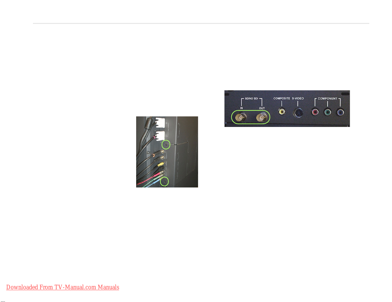
Note:
If you ordered a VIM with SDI, the SD/HD SDI connectors will
appear on the VIM. If your VIM does not have an SDI, you will only see
composite, S-video and component connectors.
9 If you have a VIM with SDI, secure the washers and nuts on
the SD/HD SDI connectors. Otherwise, go to step 10.
10 Install the screws that secure the new VIM cover.
11 Reconnect all cables, including the power cord. It is now
safe to turn on the AC power.
Downloaded From TV-Manual.com Manuals
Page 5
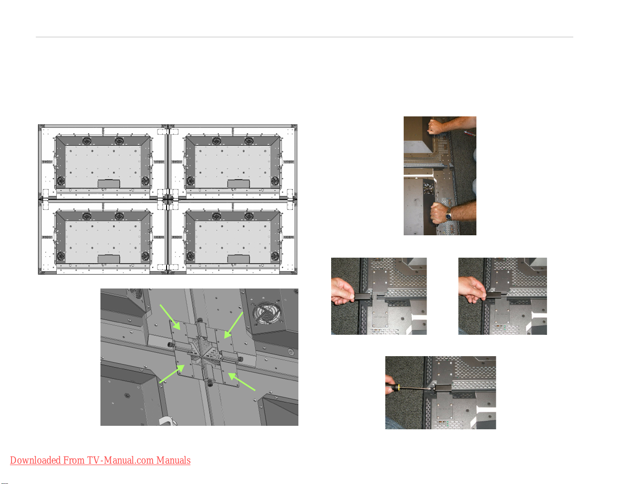
Installing Screen Brackets
Close-up view of
four brackets
attaching four
displays.
The following diagram shows where to place screen brackets if
you are tiling the m52L. Before you install a display on a wall,
install brackets on the back of the displays.
Lining Up Screen Brackets
1 Use the handles to pull displays closer together.
2 Slide the coupler over both brackets where they meet.
3 Tighten the coupler using a screwdriver.
4
Brackets
Installing Screen
Downloaded From TV-Manual.com Manuals
4 Repeat steps 1-3 for each set of displays where they meet.
Page 6

Connecting Source Cables
Analog
Input
Digital
Input
Video Inputs
Connecting Source
Cables
5
The three types of picture sources are:
• Analog computer (from UXGA
down to VGA)
• Digital computer - includes HDCP
(High-bandwidth Digital Content Protection), which prevents
the copying of digital audio and video content
• Video (optional with VIM)
• S-Video (50Hz or 60 Hz)
• Composite (NTSC, PAL or SECAM)
• Component (480i, 480p, 576i, 576p, 720p, 1080i)
• SDI (Serial digital interface inputs from 480i to 1080p)
Digital Video Interface (DVI) digitally connects computers to
their monitors or interconnects to any display.
The m52L converts the analog inputs to DVI and makes this
available at the Digital Out connector. This means you can bring
in a picture source - UXGA, SXGA, VGA, 1080p - to the first display and connect the rest of the displays in the loop with DVI.
The advantages of DVI are:
• DVI is less subject to picture degradation than analog methods
of loop-through. (Even with DVI, loop-through is not infinite.)
• DVI inputs require much less setup and adjustment. You adjust
the picture in the first display only, the display with the analog
input. Setup time is reduced.
Note: Due to copyright protection protocols, the Digital Out
connector will be disabled when viewing the HDCP DVI input.
Depending on which input is selected, the Digital Out connector will show the picture from the analog input or the digital
input.
Selecting the Correct Input
The following table gives you common examples of which
devices have which inputs. In terms of input quality, the table is
ordered from the most desirable input to the least desirable
input.
Input Found on the Following Devices
DVI Computers with digital out capability
SDI Studio quality video equipment
Analog Computers, laptops
RGB and RGBS from video processors or other profes-
sional equipment (may need BNC to DB15 adapter
cable). These may have separate sync, composite or
sync on green.
Component DVD players
Set top boxes (e.g. for cable TV or satellite TV)
Any YPbPr signal
S-Video DVD players
Set top boxes
VCRs
Composite TV tuners
VCRs
Set top boxes
Downloaded From TV-Manual.com Manuals
Page 7

Connecting Power, Turning Display On/Off
The m52L typically draws up to 4.5A at 115V or 2.25A at 230V.
For countries outside of North America, it is the responsibility of
the installer to provide the power supply cord certified for use in
the destination country.
Connect a power cable to the power supply and to an AC
source. The power supply is auto-ranging, so it works with any
source from 100 to 240 VAC, 50 to 60 Hz.
The AC Master switch is located next to the power receptacle,
both of which are located in the rear of the display.
About UPS Supplies
Some installations use a UPS - Uninterruptible Power Supply. Most UPS
devices will work with the m52L. Review
the power specifications of your UPS
device to make sure it is compatible with the m52L.
Turning Power On/Off
1 With the power cord attached, turn on the power switch
located on the back of the unit.
2 Turn on the m52L by aiming the
remote at the IR sensor in the lower
right corner of the screen (landscape)
or the lower left corner of the screen
(portrait), and pressing the
3 To turn off the m52L, press the
button.
ON button.
OFF
6
Connecting Power,
Turning It On/Off
Downloaded From TV-Manual.com Manuals
Page 8

Using the Remote and Menus
Some of these “hot keys” go
directly to the most-used
menus. Some of them go to
several menus, if you push the
button more than once.
SOURCE, SETUP and CURTAIN
perform special actions
without menus.
Pressing the up/down
arrow keys moves the
select bar (yellow
highlight in the menus).
The –/+ (left/right)
arrow keys change
values in the selected
item. The right arrow
can also take you to the
next menu.
Pressing
MENU opens
the
MAIN MENU.
Pressing PREV reverts to the
previous menu.
Pressing
ENTER moves to the
next menu, when it has a rightpointing arrow, or it toggles
the highlighted item on and
off.
Main Menu
Picture
Size & Position
Aspect Ratio & Wall
Memory
Diagnostics
Advanced Options
Program Information
Using the Remote Control
The remote control works much like a remote control for a TV or
Using the
7
Downloaded From TV-Manual.com Manuals
DVD player, but it does more. Among other things, it opens
menus, changes values and moves the image.
The remote control operates with IR (infrared) signals going to
the IR receiver, which is located behind the lower center of the
screen.
Remote, Menus
To open menus on the m52L, aim the remote at the screen and
press the desired button(s).
Using the Menus
The m52L’s menus and functions are arranged in groups and
can be accessed through grouped functions or by using direct
access keys. The starting point for accessing menus is the
button on the remote.
1 Press
MENU on the remote to display the MAIN MENU.
2 Use the up/down arrow keys to move through menu
options. See explanations next to the remote control picture on this page for additional navigation information.
Some of the setups described in this Quick Start Guide will
explain how to navigate through specific menus. Most of the
menus are explained in detail in the Installation Guide CD.
MENU
Page 9

Selecting a Source
In this guide, a source is any type of picture. It might be an analog computer image, a video processor, a VCR or DVD, or it
might be a DVI picture from a computer.
Selecting the Source Automatically
1 Press SOURCE on the remote. The
m52L goes to the next connector that
has a valid picture on it and displays
that picture.
2 If you want to select a different
source, press
SOURCE again to select
the next connector (that has a valid
picture on it) and display the picture.
If a connector does not have a valid source, the m52L briefly
Note:
displays that it has scanned that connector and then proceeds to the
next connector.
Selecting the Source Manually
1 Press FREQ/PHASE on the remote. The m52L displays the
PICTURE menu for the current source.
Picture
Source Digital
Vertical Frequency (frame locked) 60Hz
Horizontal Frequency 50.00kHz
Horizontal Resolution 1366
Vertical Resolution 768
Sharpness 4
2 Using the up/down arrows, select the
press
ENTER.
The SOURCE submenu displays to the right of the PICTURE
Note:
menu.
SOURCE line and
3In the SOURCE submenu, use the up/down arrow keys to
select the desired source.
4 When the desired source is selected, press
TURE menu changes to display the settings for that
ENTER. The PIC-
source.
When the Source is Familiar to m52L
When a “new” source is selected, the m52L looks through a list
of the last 10 picture types it used. If the “new” source is like a
previous one in this list (resolution, number of active lines, etc.),
the m52L uses the stored data and does not do anything in the
AUTO SETUP OPTIONS menu. This saves time, and the picture is
displayed faster without going through adjustments, which are
visible on the screen.
Best Way to Change a Source
The best way to select a source is to recall a configuration your
installer has created for you. See the Installation Guide CD for
more detailed information.
1 On the remote, press
2 Using the arrow keys, scroll to one of the numbered con-
figurations your installer has created for you.
3 Press
4With the
ENTER to show the RECALL SLOT menu.
RECALL NOW line selected, press ENTER. If the top
of the menu displays “Current,” the source is identical to
the settings stored in the memory slot.
SAVE. The RECALL menu displays.
8
Selecting a Source
Downloaded From TV-Manual.com Manuals
Page 10

Adjusting Levels for Analog Sources
Input Levels
Auto Black Level (offset)
Auto White Level (gain)
Center Point 64 124 99
Black Level (offset)-All 79
Red 89
Green 67
Blue 83
White Level (gain)-All 99
Red 99
Green 99
Blue 99
This page applies to analog RGB (computer) pictures only. The
levels are best adjusted semi-automatically.
For analog RGB pictures, the levels for black and white vary from
one computer to another, or from one video processor to
another. They even vary between video outputs from a multiple-output video card in a computer.
Your pictures will not look their best on the m52L until you
adjust for these differences. This is not about adjusting color or
contrast. It’s about telling the m52L what the computer or processor means by black and by white.
Semi-Automatic Level Adjustment
1 Select a source in the PICTURE menu. Display an all-black
picture from the source computer. This must come from the
computer source that will be used for the program.
We suggest displaying a black screen using Windows® Paint.
Note:
2 To open the INPUT LEVELS menu, press LEVEL.
3 Select
Note:
analog input, the color of the picture will change while it is working,
then it will change back to normal.
4 Display an all-white picture from the source computer.
5In the
6 The m52L is now adjusted to the black and white levels of
Adjust Levels,
Analog
9
Downloaded From TV-Manual.com Manuals
7 Save the configuration to a memory slot.
AUTO BLACK LEVEL and press ENTER. This menu line
says “Working…” until the process is complete.
When doing Auto Black and Auto White with an interlaced
INPUT LEVELS menu, select AUTO WHITE LEVEL and
press
ENTER. Wait for “Working…” to disappear.
this computer using this video card. If you change computers or video output cards in the computer, you must
do this again.
Manual Level Adjustment
1 Select a source in the PICTURE menu. Display an all-black
picture from the source computer.
2In the
3Select
4 Display an all-white picture from the source computer.
5Adjust
6 Although it’s not required, it is recommended that you
INPUT LEVELS menu, Press LEVEL on the remote.
BLACK LEVEL and adjust it up and down with the
-/+ keys to make the three center point values go to zero.
Once any value reaches zero, use the individual colors
under
BLACK LEVEL to adjust the other two values to zero.
WHITE LEVEL until the image maximums just go to
255. Once any value reaches 255, use the individual colors
under white level to adjust the other two values to 255.
save the configuration to a memory slot. See the Installa-
tion Guide CD for more information.
Page 11

Adjusting Input Levels and Position
Input Levels
Brightness 140
Contrast 165
Saturation 150
Hue 128
Blue Only
Adjust
brightness so
you can’t see
the
difference
between
these two
marks
But you can you ca n
see the difference
between these two
marks
10
Adjust Input
Levels, Position
Adjusting Levels for Video Sources
Video sources are adjusted best if a color bar test pattern is
available from the video source: the DVD or VCR player. If not,
you will have to adjust by eye and the “feel” of the picture.
When a video source is selected, Auto Setup Options are not
Note:
available. Adjustments must be made manually.
Adjusting the Picture
1 Select a video source in the PICTURE menu.
2 Press
3 Adjust one of the following:
Adjusting With Color Bars
1 If possible, use a SMPTE color bar pattern from the video
2In the
3Adjust
Downloaded From TV-Manual.com Manuals
4Adjust
5 Uncheck
LEVEL on the remote to open INPUT LEVELS.
• Any picture from the video source.
• Using a standard SMPTE color bar pattern from the source.
source you will use for the program material.
INPUT LEVELS menu, check BLUE ONLY. You should
see the alternate color bars, all of them blue.
SATURATION to make the outer two color bars
match. Match them in brightness; they will already match
in color.
HUE to make the inner two color bars match.
BLUE ONLY.
6 If the color bar pat-
tern has a pluge
(Picture Line-Up
Generation Equipment), you can use
it to adjust brightness. Pluge is used
to calibrate the
black level on a
video monitor.
7 Although it’s not
required, it is recommended that you save the configuration to a memory slot. See the Installation Guide for more
information about saving memory slots.
Adjusting Position
Position moves the picture on the screen but does not move the
menus. Press
POSITION menu. The four arrow keys move the picture on the
screen.
The numbers for Horizontal and Vertical Position refer to the
number of pixels from sync to the first displayed pixel. These
numbers get smaller as the picture moves up and to the left.
The Horizontal Position number shows the number of pixels
from the beginning of H sync to the first active pixel. Because
there are many black pixels after H sync, this number will not be
zero when the picture is at the left border of the screen.
The Vertical Position number is the number of lines from V sync
to the first active line, so it will not be zero when the picture is at
the top of the screen.
SIZE/POS on the remote once to open the PICTURE
Page 12

Color Balancing for One Display
Color Balance
Color Temperature Native
White Balance - All (Clipboard)
Red 100 (100)
Green 100 (100)
Blue 100 (100)
Gray Balance - All
Red 7 (7)
Green 7 (7)
Blue 7 (7)
Tes t P at te rn Off
Hide Menu
Copy to Clipboard
Recall From Clipboard
Reset to Defaults
Color Balancing
11
Color Balance is used to match the colors of adjacent displays
when several displays are arranged in an array. You can also use
it to adjust the color of a single display.
For one display, the Color Balance controls can be used to set
the color temperature of that display.
1 To access the
COLOR BALANCE menu, press MISC once on
the remote.
2 The m52L defaults to the brightest setting possible, which
is 100 in the red, green and blue lines under
ANCE. You can choose a different color temperature by
setting it in the
3 Select the
COLOR BALANCE menu.
COLOR TEMPERATURE line and then select from
WHITE BAL-
3200°K (Warm), 5500°K, 6500ºK and 8500°K (Cool). If you
want the brightest display, select the
Changing the color temperature changes the three WHITE
Note:
BALANCE values. You can also change the WHITE BALANCE values
individually to create a custom color temperature. Once you have
changed the values, a new
TEMPERATURE line.
CUSTOM option is available on the COLOR
NATIVE option.
Downloaded From TV-Manual.com Manuals
Page 13

Color Balancing for Multiple Displays
Color balancing makes the individual displays in an array show
the same colors. Colors vary slightly from one display to the
next, because of slight variations in the backlights and display
panels. Color balancing can compensate for this.
When your wall is first installed, the installer will run an ACB and
then perform manual color balance adjustments.
Note:
You can manually color balance after an ACB to fine-tune
settings. These will be kept even after another ACB is performed.
Manual Color Balancing
To color balance, you only have to match whites and grays.
When you make all the displays look the same with white and
gray, all the other colors will look the same.
Caution: Do not match the colors of the displays with the Black and
White Level controls or with the video controls.
Caution: If you are color blind, even a little bit, do not color balance
your array. Have someone else color balance the wall.
1 Turn on all the displays in the array and let them warm up
for at least five minutes. The backlights must be thoroughly warm before you color balance.
2 On each display, open the
(
MENU > ADVANCED OPTIONS > BACKLIGHT SETTINGS).
3Set
BACKLIGHT CONTROL MODE to MANUAL.
4 Set (or confirm)
BACKLIGHT INTENSITY to 10 (100%).
5 On each display, open the
pressing
MISC once on the remote.
6 If the array has never been color balanced, make sure you
start with the
NATIVE color temperature option on each
BACKLIGHT CONTROL menu
COLOR BALANCE menu by
display. If you don’t need a specific color temperature, use
NATIVE, which is the brightest.
7 On each display, highlight
right arrow keys until the menu displays
Always use the internal Test Patterns for color balancing.
Note:
TEST PATTERN and use the left/
WHITE.
8 When all displays are white, find the least bright display in
the array. This will be the “baseline” display, and you will
not adjust it. All other displays will be adjusted to this
baseline display.
9 Choose a display next to the baseline display and adjust
its white values (red, green and blue) to make it match the
baseline display. Concentrate on the center of the displays, not the adjacent edges.
10 Continue with other adjacent displays until all the displays
have the same appearance when white. Be careful not to
change the values of displays once you are satisfied with
them.
11 When all displays look the same when showing the White
test pattern, select the Gray test pattern in all displays.
12 Choose any display as the new baseline display. It does
not need to be the baseline display you used for white.
13 Adjust gray for all the displays until they match the base-
line display. Do one display at a time. Again, match the
center part of the picture, not the edges.
14 When all displays match in gray, close all the menus. The
test pattern automatically turns off.
12
Color Balancing
Downloaded From TV-Manual.com Manuals
Page 14

Recommended Usage
Recommended
Usage
13
In order to get the most out of your m52L, use the following
recommended guidelines to optimize the display.
Burn-In Versus Temporary Image Retention
Burn-in causes the screen to retain an image essentially forever,
with little or no way to correct the problem. Under normal use,
an m52L will not experience burn-in, as plasma displays do, nor
will it retain images in any way.
Normal use of a m52L is defined as displaying continuously
changing video patterns or images. However, m52Ls can experience temporary image retention when recommended usage
guidelines are not followed.
What is Temporary Image Retention?
Temporary image retention (TIR) can occur when a static image
is displayed continuously for extended periods of time (12 hours
or longer). An electrical charge differential may build up
between the electrodes of the liquid crystal, which causes a
negative-color video image (color-inverted and brightnessinverted version of the previous image) to be retained when a
new image is displayed. This behavior is true for any LCD device
from any LCD manufacturer.
Note:
Normal use of any LCD device does not cause TIR.
Static Image Applications
Typical static image applications include airports, transit stations, stock markets, banks, and command/control installations,
or anywhere a fixed image is displayed continuously for 12 or
more hours.
Static Image Display Guidelines
Here are some guidelines to help you avoid TIR:
• Use the m52L to show moving images or still pictures that
change regularly.
• Turn the display off when it is not in use. There are several ways
to do this automatically:
• To use the display’s real-time clock, schedule an event. See
the Installation Guide CD for information.
• To use your source computer’s Power Options Properties,
set up your computer to turn off the monitor when not in
use. You also need to check the
DPMS DELAY box in the BACKLIGHT CONTROL menu.
• To use RS232 commands, see the Installation Guide CD.
Caution: It is suggested that you turn off the backlight power for six
hours per day. When using high-contrast images, reposition the
images frequently.
DPMS checkbox and set the
Normal Use Thermal Guidelines
Normal use of an m52L is defined as operating in the open air to
prevent heat buildup, and without direct or indirect heat
sources such as adjacent displays, lighting fixtures, heating
ducts, or direct sunlight that can cause the display to experience
high operating temperatures. At 2000m or below, the maximum
ambient operating temperature cannot be above 35º C (30º C
with cover glass) nor below the minimum ambient operating
temperature of 0º C. If one of these conditions exists, it is up to
the installer to ensure that display placement is changed, thermal shielding is provided and/or additional ventilation is provided to keep the display within its nominal operating
parameters.
Downloaded From TV-Manual.com Manuals
Page 15

Declaration of Conformity
Manufacturer's Name: Planar Systems, Inc.
Manufacturer's Address: 1195 NW Compton Drive
Beaverton, OR 97006
Declares that the products
Model Numbers: m52L (Direct-view LCD)
Conforms with the provisions of:
Council Directive 2004/108/EC on Electromagnetic Compatibility;
EN55022:1998 Radiated and Conducted Emissions from IT Equipment
EN55024:1998 Immunity of IT Equipment
Including: EN61000-4-2 Electrostatic Discharge
EN61000-4-3 Radiated Immunity
EN61000-4-4 Electrical Fast Transients
EN61000-4-5 Line Surge
EN61000-4-6 RF Conducted Susceptibility
EN61000-4-8 Magnetic Field Immunity
EN61000-4-11 Voltage Dips and Interrupts
And: EN61000-3-2 Harmonic Current Emissions
EN61000-3-3 Voltage fluctuations and Flicker
Council Directive 2006/95/EC on Low Voltage Equipment Safety:
EN60950:2001 Safety of IT Equipment
The Technical Construction File required by this Directive is maintained at the corporate headquarters of Planar Systems, Inc., 1195 NW Compton Drive, Beaverton,
OR 97006.
14
Conformity
Note: This equipment has been tested and found to comply with the limits for a Class A digital device, pursuant to part 15 of the FCC Rules. These limits are
designed to provide reasonable protection against harmful interference when the equipment is operated in a commercial environment. This equipment generates,
uses, and can radiate radio frequency energy and, if not installed and used in accordance with the instruction manual, may cause harmful interference to radio
communications. Operation of this equipment in a residential area is likely to cause harmful interference in which case the user will be required to correct the
interference at his own expense.
Industry Canada (ICES-003): This Class A digital apparatus complies with Canadian ICES-003.
Cet appareil numérique de la classe A est conforme à la norme NMB-003 du Canada.
Any changes or modifications to the display not expressly approved by Planar could void the user's authority to operate this equipment.
Other Certifications: CISPR 22
Downloaded From TV-Manual.com Manuals
 Loading...