

Page 1
Planar LookThru Transparent OLED Display User Manual
020-1380-00
Page | 1
User Manual
Planar LookThru
Transparent OLED Display
LO552
LO552-S
Page 2

Planar LookThru Transparent OLED Display User Manual
020-1380-00
Page | 2
Copyright © August 2019 by Leyard Optoelectronics Co., Ltd. and Planar Systems, Inc.
All rights reserved.
This document may not be copied in any form without permission from Leyard or Planar.
Information in this document is subject to change without notice.
Trademark Credits
Planar® LookThru™ is a trademark of Planar Systems, Inc.
All other companies are trademarks or registered trademarks of their respective
companies.
Disclaimer
The information contained in this document is subject to change without notice. Leyard
and Planar Systems, Inc. makes no warranty of any kind with regard to this material.
While every precaution has been taken in the preparation of this manual, the Company
shall not be liable for errors or omissions contained herein or for incidental or
consequential damages in connection with the furnishing, performance, or use of this
material
Warranty and Service Plans
Planar warranty and service plans will help you maximize your investment by providing
great support, display uptime, and performance optimization. From post-sale technical
support, to a full suite of depot services, our services are performed by trained
employees. When you purchase a Planar product, you get more than a display; you get
the service and support you need to maximize your investment. To find the latest
warranty and service information regarding your Planar product, please visit
http://www.planar.com/support or http://www.leyard.com/en/support/
RoHS Compliance Statement
The Planar LookThru LO552 series is fully RoHS compliant.
Part Number: 020-1380-00
Page 3

Planar LookThru Transparent OLED Display User Manual
020-1380-00
Page | 3
Table of Contents
Table of Contents
Introduction ................................................................................................................. 6
1. Safety Information ........................................................................................................... 7
1.1 Safety Precautions ................................................................................................ 7
1.2 Important Safety Instructions ................................................................................ 8
2. Recommended Usage ..................................................................................................... 9
3. Important Waste Disposal Information ........................................................................... 10
Tour of the Planar LookThru Transparent OLED Product Family .................................... 11
4. Display Architecture ....................................................................................................... 11
5. Package Contents ......................................................................................................... 15
5.1 Accessories .........................................................................................................16
Unpacking and Installing the Display ............................................................................ 19
6. Safe Handling ................................................................................................................ 19
7. Environmental Considerations ....................................................................................... 20
8. Installation Disclaimer .................................................................................................... 20
9. Requirements for All Installations .................................................................................. 20
10. Multiple Displays ........................................................................................................... 22
Operating the Display ................................................................................................. 23
11. OSD Keypad ................................................................................................................. 23
12. OSD Keypad Buttons .................................................................................................... 24
13. Using the Remote Control ............................................................................................. 24
13.1 Display .............................................................................................................25
13.2 Remote Control ................................................................................................25
13.3 External Control ...............................................................................................25
IR Command Protocol ................................................................................................. 26
14. Locking the Keypad and IR Remote ............................................................................... 28
15. Unlocking the Keypad and IR Remote ............................................................................ 28
16. Turning the Display On .................................................................................................. 29
17. Turning the Display Off .................................................................................................. 29
Page 4

Planar LookThru Transparent OLED Display User Manual
020-1380-00
Page | 4
Table of Contents
18. Image Optimization Algorithms ...................................................................................... 29
19. LED Indicators ............................................................................................................... 30
Navigating Through the Menus .................................................................................... 31
20. Inputs and Views Menu .................................................................................................. 32
20.1 Advanced Layouts Submenu ............................................................................33
21. Image Adjust Menu........................................................................................................ 34
22. Audio Menu ................................ ................................................................ ................... 37
23. Presets Menu ................................................................................................................ 38
24. Advanced Settings Menu ............................................................................................... 39
24.1 Panel Brightness Submenu ..............................................................................39
24.2 Power Submenu ...............................................................................................40
24.3 Network Submenu ............................................................................................41
24.4 Menus and Messages Submenu ................................ ......................................42
24.5 Schedule Submenu ..........................................................................................43
24.6 EDID Submenu ................................................................................................45
25. Tiling ............................................................................................................................. 48
25.1 Comments about Frame Compensation ...........................................................49
25.2 System Settings Submenu ...............................................................................50
26. Information Menu .......................................................................................................... 51
26.1 System Information Submenu ..........................................................................51
26.2 Image Information Submenu ............................................................................51
26.3 Error Log Submenu ..........................................................................................52
Developing Content .................................................................................................... 53
Signal Compatibility.................................................................................................... 54
Troubleshooting ......................................................................................................... 58
Maintenance .............................................................................................................. 59
27. Cleaning the Display ...................................................................................................... 59
27.1 Metal Surfaces .................................................................................................59
27.2 Cleaning Front AR Glass ..................................................................................59
27.3 Cleaning the Backside of the Display Glass .....................................................60
Specifications ............................................................................................................. 61
Line Drawings ............................................................................................................. 63
Page 5

Planar LookThru Transparent OLED Display User Manual
020-1380-00
Page | 5
Table of Contents
28. Standard Design ............................................................................................................ 63
29. Straight Mount Design ................................................................................................... 65
Accessing Leyard’s Technical Support Website ............................................................. 67
Regulatory Information ............................................................................................... 68
Page 6

Planar LookThru Transparent OLED Display User Manual
020-1380-00
Page | 6
Introduction
Introduction
The Planar® LookThru™ Transparent OLED Display showcases dynamic or interactive
information on a transparent surface glass. This display allows users to view what is
shown on a glass video screen while still being able to see through it. Designers can
overlay text, digital images, and video content onto physical objects or scenes that sit
behind the glass.
Truly See-Through Installations
The first-of-its-kind Planar LookThru is a self-emitting display that utilizes Organic Light
Emitting Diode (OLED) to eliminate the need for a backlight or enclosure, making it
possible to create truly see-through installations. The design offers virtually frameless
glass with up to 45 percent light transmissivity, creating clear, unobstructed views of
objects, scenes, or other digital screens behind the transparent display.
Flexible Design Options
The Planar LookThru measures 55-inch in diagonal. It can be used in both portrait and
landscape modes, and can be table mounted, ceiling mounted, or built into custom
fixtures. It can also be tiled to create large, eye-catching video wall arrays.
Brilliant Picture Quality in a Large Viewing Size
The Planar Lookthru offers vibrant colors greater than 100 percent National Television
System Committee (NTSC) performance as well as wide viewing angles with no off-axis
contrast or brightness limitations. The display provides Full HD resolution that allows for
beautiful graphics and full-motion video.
High Durability
The Planar LookThru features the proprietary Planar® Extended Ruggedness and
Optics™ (ERO™) technology, which uses a protective optically-clear Corning® Gorilla®
Glass bonded to the front surface of the display. This high-durability surface can
withstand the rigors of high-traffic environments and interactive touch.
Source Compatibility
The Planar LookThru comes with standard digital inputs including HDMI and DisplayPort,
is fully controllable using RS-232, LAN, Crestron and other control systems, and is
compatible with sources ranging from PCs and players to consumer video devices that
rely on High-bandwidth Digital Content Protection (HDCP) compliance. The display is
compatible with processing solutions for tiling applications or advanced source
management.
Page 7

Planar LookThru Transparent OLED Display User Manual
020-1380-00
Page | 7
Introduction
1. Safety Information
Before using the Planar LookThru LO552 display, please read this manual thoroughly to
help protect against damage to property and to ensure personal safety.
Be sure to observe the instructions.
For safety, be sure to observe ALL the warnings detailed in this manual.
For installation or adjustment, please follow this manual’s instructions and refer all
servicing to qualified service personnel.
1.1 Safety Precautions
If water is spilled or objects are dropped inside the display, remove the power
plug from the outlet immediately. Failure to do so may result in fire or electrical
shock. Contact the dealer for inspection.
If the display is dropped or the chassis is damaged, remove the power plug
from the outlet immediately. Failure to do so may result in fire or electrical shock.
Contact the dealer for inspection.
If the power cord or plug is damaged or becomes hot, turn off the main power
switch of the display. Make sure the power plug has cooled down and remove
the power plug from the outlet. If the display is still used in this condition, it may
cause a fire or an electrical shock. Contact the dealer for a replacement.
Caution: Wall and/or support mounts must be secure.
If a display or displays are hung from a wall or some other support, the structure must be
verified as able to safely sustain the weight of the assembly. Simply mounting to
wallboard or wall paneling won’t be adequate or safe.
Page 8

Planar LookThru Transparent OLED Display User Manual
020-1380-00
Page | 8
Introduction
1.2 Important Safety Instructions
1. Read these instructions.
2. Keep these instructions.
3. Heed all warnings.
4. Follow all instructions.
5. Do not use Planar LookThru LO552 displays outdoors or near water.
6. Do not install near any heat sources such as radiators, heat registers, stoves or other
apparatus that produce heat.
7. Do not defeat the safety purpose of a polarized or grounding type plug. The
polarized plug has two blades with one wider than the other. A grounding type plug
has two blades and a third grounding prong. The wide blade or the third prong is
provided for safety. When the provided plug does not fit into an outlet, consult an
electrician for the replacement of the obsolete outlet.
8. Protect the power cord(s) from foot traffic or kinks particularly at plugs, convenience
receptacles and the point where they exit from any of the Planar LookThru displays.
9. Use only replacement parts, accessories and other components specified by Planar
Systems.
10. Unplug all Planar LookThru displays during lightning storms or when unused for long
periods of time.
11. Follow all National Electrical Code regulations. In addition, be aware of local codes
and ordinances when installing the system.
12. Refer all servicing to qualified service personnel. Servicing is required when any
Planar LookThru displays have been damaged in any way, such as when the AC
power cord or plug is damaged, liquid has been spilled or objects have fallen into a
product, the products have been exposed to rain or moisture, do not operate
normally or have been dropped.
13. Consider keeping the packing materials in case the equipment ever needs to be
shipped.
14. Wall mounts must be secure. The wall must be strong enough to hold all Planar
LookThru displays, mounting plates, cables and accessories. Weights and
dimensions of components of the display are found in the “Specifications” section on
page 61.
Page 9

Planar LookThru Transparent OLED Display User Manual
020-1380-00
Page | 9
Introduction
2. Recommended Usage
In order to get the most from the Planar LookThru LO552 display, use the following
recommended guidelines to optimize the display.
Planar LookThru displays are designed for fixed installation, indoor use only.
Normal use definition: 12 hours per day at 25ºC, moving image, 75 nits average
luminance
In use, the Planar LookThru LO552 display should be operated in the open air to prevent
heat buildup and without direct or indirect heat sources such as nearby lighting fixtures or
heating ducts that can cause the display to experience elevated temperatures.
If the display will be installed in a recessed area with a surround trim or other enclosing
feature around the Planar LookThru LO552 electronic box, ensure adequate openings
are provided for proper air flow and ventilation.
At sea level, the maximum ambient operating temperature for the Planar LookThru
display cannot exceed 40° C nor be below a minimum ambient operating temperature of
0° C. If one of these conditions is exceeded, it is up to the installer to ensure that display
placement is changed, thermal shielding is provided, and/or additional ventilation is
provided to keep the system within its nominal operating parameters.
For proper cooling, the electronic box should not be mounted closer than the spacing
described in the “Requirements for All Installations” section on page 20 to any continuous
surface. The perforated sheet metal on all sides of the Planar LookThru electronic box
must be kept clear of obstruction or any sort of cover.
Page 10

Planar LookThru Transparent OLED Display User Manual
020-1380-00
Page | 10
Introduction
3. Important Waste Disposal Information
Please recycle or dispose of all electronic waste in accordance with local, state, and
federal laws. Additional resources can be found online at
http://www.planar.com/about/green/
The crossed-out wheelie bin symbol is to notify consumers in areas subject to Waste
Electrical and Electronic Equipment (WEEE) Directive 2012/19/EU that the product was
placed on the market after August 13, 2005 and must not be disposed of with other
waste. Separate collection and recycling of electronic waste at the time of disposal
ensures that it is recycled in a manner that minimizes impact to human health and the
environment. For more information about the proper disposal of electronic waste, please
contact the local authority, the household waste disposal service, or the seller from which
the product was purchased.
Page 11
Planar LookThru Transparent OLED Display User Manual
020-1380-00
Page | 11
Tour of the Planar LookThru Transparent OLED Product Family
Tour of the Planar
LookThru Transparent
OLED Product Family
4. Display Architecture
The two members of the Planar LookThru LO552 product family are described in this
section:
LO552 Standard Model
LO552-S Straight Mount Model
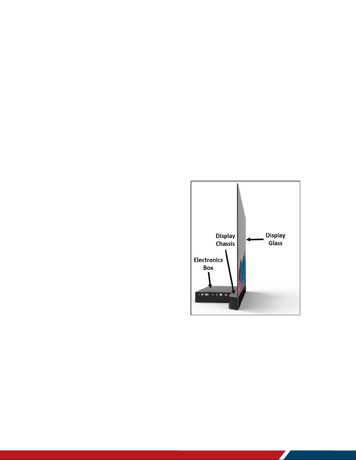
These two Planar LookThru models are
made up of three subcomponents:
Display Glass
Display Chassis
Electronic box
The Standard Model of the Planar
LookThru LO552, pictured on the right, is
intended for use on a tabletop or attached
to a suitable surface, either upright as
shown, inverted (landscape mode) or sidemounted in portrait mode. Tiled installation
is also possible.
The Display Glass consists of two pieces
of 2 mm thick Corning Gorilla Glass and a
55-inch diagonal TAMOLED (Transparent
Active Matrix Organic Light Emitting Diode) panel. These components are optically
bonded together employing the proprietary Planar ERO process. Use of Planar ERO
results in a combination of optimum optical performance and ruggedness. The glass
assembly, featuring a front surface anti-reflective coating, is less than 8 mm thick. Bezel
dimensions on the left, right, and top side of the display glass is 6.9 mm.
The Display Glass should never be used as the main load-bearing element for mounting
or as a primary handle or principal support during transport.
The Display Glass is securely joined to the display where that attachment surface creates
the bottom bezel for the Planar LookThru LO552. That bezel width is 95 mm. The Display
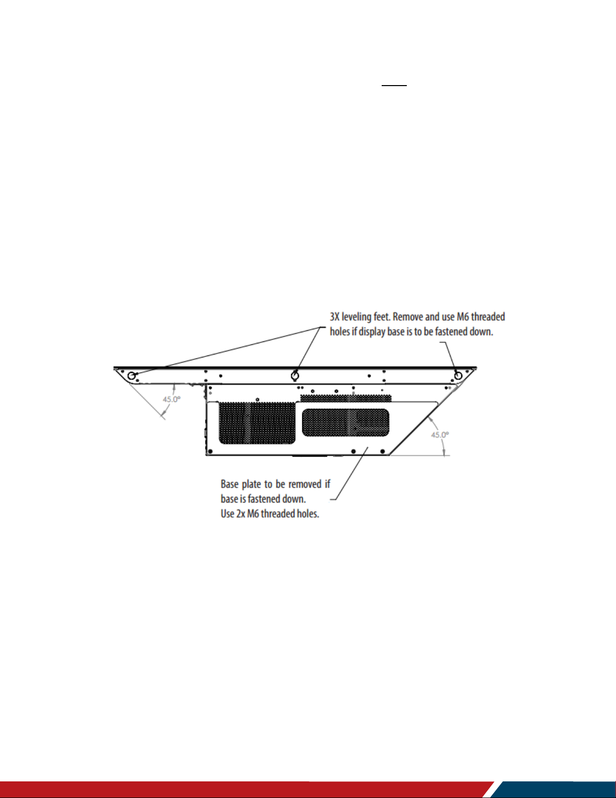
Chassis also incorporates the five primary M6 mounting points. Leveling feet are installed
in three of these mounting points in the Planar LookThru LO552. The feet should be
Page 12
Planar LookThru Transparent OLED Display User Manual
020-1380-00
Page | 12
Tour of the Planar LookThru Transparent OLED Product Family
removed for a fixed mounting installation. No fewer than three of the primary mounting
holes are recommended to be used for any installation. The Display Chassis is the part of
the display to use as a primary handhold during transport and mounting.
There are five secondary M6 mounting points on the underside of the electronic box.
These should only be used together with the primary mounting points on the Display
Chassis, but never by themselves. A counter weight is attached to the underside of the
electronic box in the Planar LookThru LO552. The counter weight also serves to create
an acceptable open space for ventilation on the underside of the display. Like the leveling
feet, it should be removed for a fixed mount installation, but provisions must be made for
the proper 5 mm inch spacing.
Note that the corners of the Display Chassis and the right side (viewed from the front) of
the electronic box are chamfered at a 45º angle, allowing a corner or right-angle
installation of Planar LookThru LO552 displays. This is a feature found in all the LO552
family of displays. The bottom view of a Planar LookThru LO552 in the figure below
illustrates the corner chamfers. The leveling feet and counterweight are also shown.
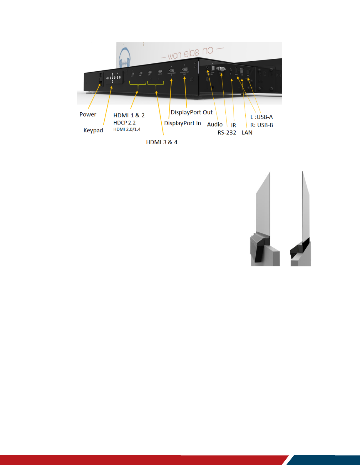
The backside of the electronic box also contains the controlling I/O for the display. This is
shown in the figure below. The power switch and power cord receptacle are centered on
the backside.
The keypad is described in detail in the “OSD Keypad” section on page 23. There are
four HDMI connectors consisting of two HDMI 2.0 compliant and two HDMI 1.4 compliant
inputs. Additionally, there is a DisplayPort 1.2 input and a corresponding DisplayPort
output. The RS-232 and LAN connectors are found on the right side of the electronic box
along with the jack for the remote sensor as well as USB-A and USB-B ports.
Page 13
Planar LookThru Transparent OLED Display User Manual
020-1380-00
Page | 13
Tour of the Planar LookThru Transparent OLED Product Family
Note there is no fan in any of the Planar LookThru LO552 family of displays.
The Straight Mount Model, the Planar LookThru LO552-S, on
the right, is intended to allow mounting on a wall or partition
where space behind the Display Chassis is an issue. Like the
Standard Model, the Planar LookThru LO552-S can be used in
the tiled configuration. The Planar LookThru LO552-S differs
from the Standard Model in that the electronic box has been
relocated 90º downward compared to the Planar LookThru
LO552. It is functionally identical to the Planar LookThru
LO552. The Planar LookThru LO552-S can be mounted in
upright or inverted in landscape mode or in either orientation in
portrait mode. A corner installation of multiple LO552-S
displays is also possible.
Note that the Straight Mount Model is not intended for standalone use; it can only be
used when attached to a support structure.
The primary mounting points on the Display Chassis must be employed for attachment.
The secondary mounting points on the electronic box can also be used, but only along
with the primary points.
Page 14

Planar LookThru Transparent OLED Display User Manual
020-1380-00
Page | 14
Tour of the Planar LookThru Transparent OLED Product Family
The two models of the Planar LookThru LO552 display family are summarized in the
table below:
Planar LookThru
Transparent OLED
Model
Part Number
Description
Figure
LO552
998-1483-00
Standard Model
LO552-S
998-1484-00
Straight Mount
Model
Page 15
Planar LookThru Transparent OLED Display User Manual
020-1380-00
Page | 15
Tour of the Planar LookThru Transparent OLED Product Family
5. Package Contents
Part
Description
Number
Picture
Display
One per box.
1
AC Power
Cord
North American
power cord.
1
IR Extender
Cable
Used to receive
signals from the
remote control.
1
HDMI Cable
HDMI cable.
1
Remote
Control
Used to control
the display.
1
Batteries
AA batteries
1
Quick Start
Guide
Quick start
guide.
1
Page 16
Planar LookThru Transparent OLED Display User Manual
020-1380-00
Page | 16
Tour of the Planar LookThru Transparent OLED Product Family
5.1 Accessories
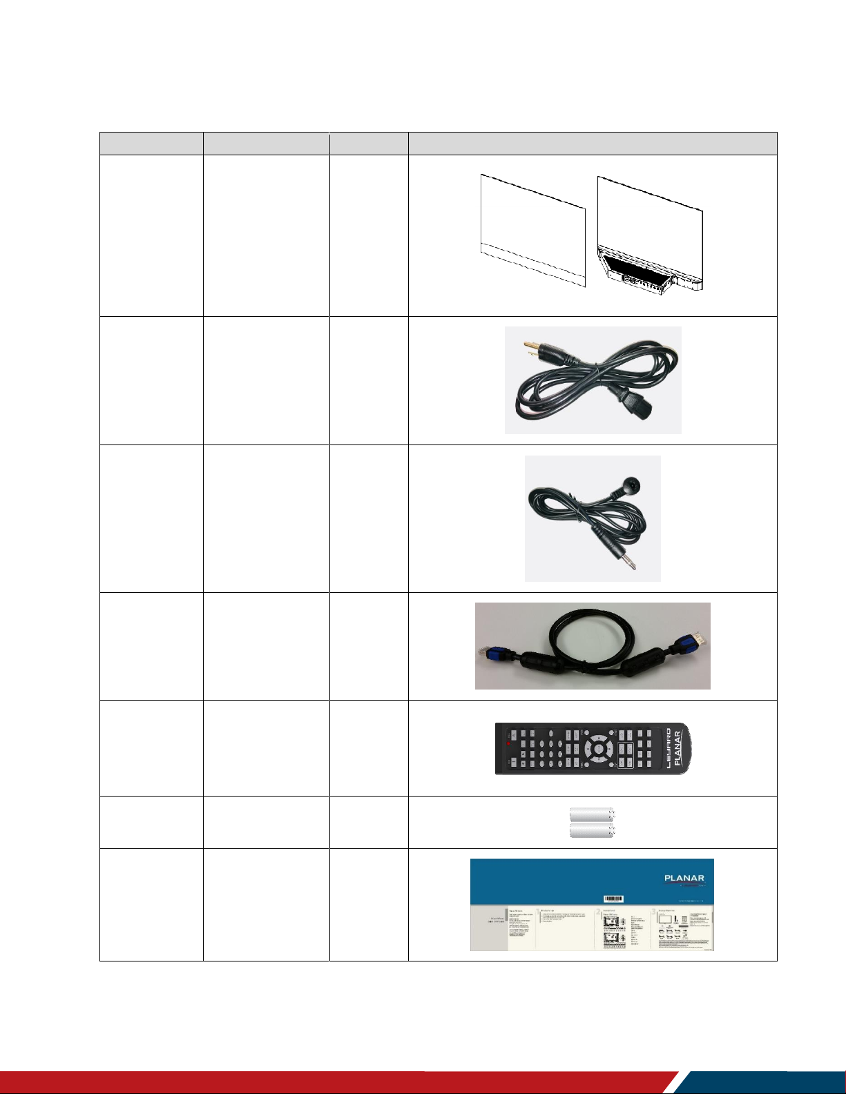
Platform Cover
The perforations in the electronic box must not be covered
significantly in any way. Rather than placing items of interest on
the electronic box, we recommend the use of the Platform
Cover that consists of the sheet metal plate and support feet.
There are two magnetic feet that attach to the steel
components of the Display Chassis. The figure on the right
illustrates the use of the Platform Cover.
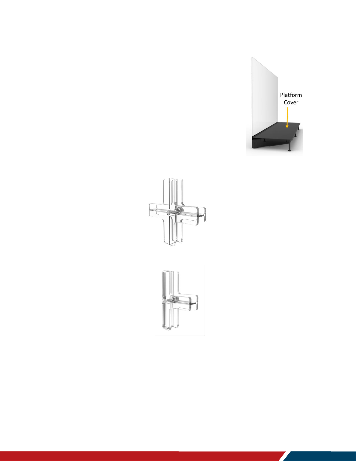
Tiling Hardware
The Tiling Hardware can be used in tiled installations, either for
flat or corner mounts. There are four tiling assemblies, all made
of up of an interlocking front and back component:
Cross sign shape for flat (2x2 Panels)
T-shape for flat (2x1 Panels)
Page 17
Planar LookThru Transparent OLED Display User Manual
020-1380-00
Page | 17
Tour of the Planar LookThru Transparent OLED Product Family
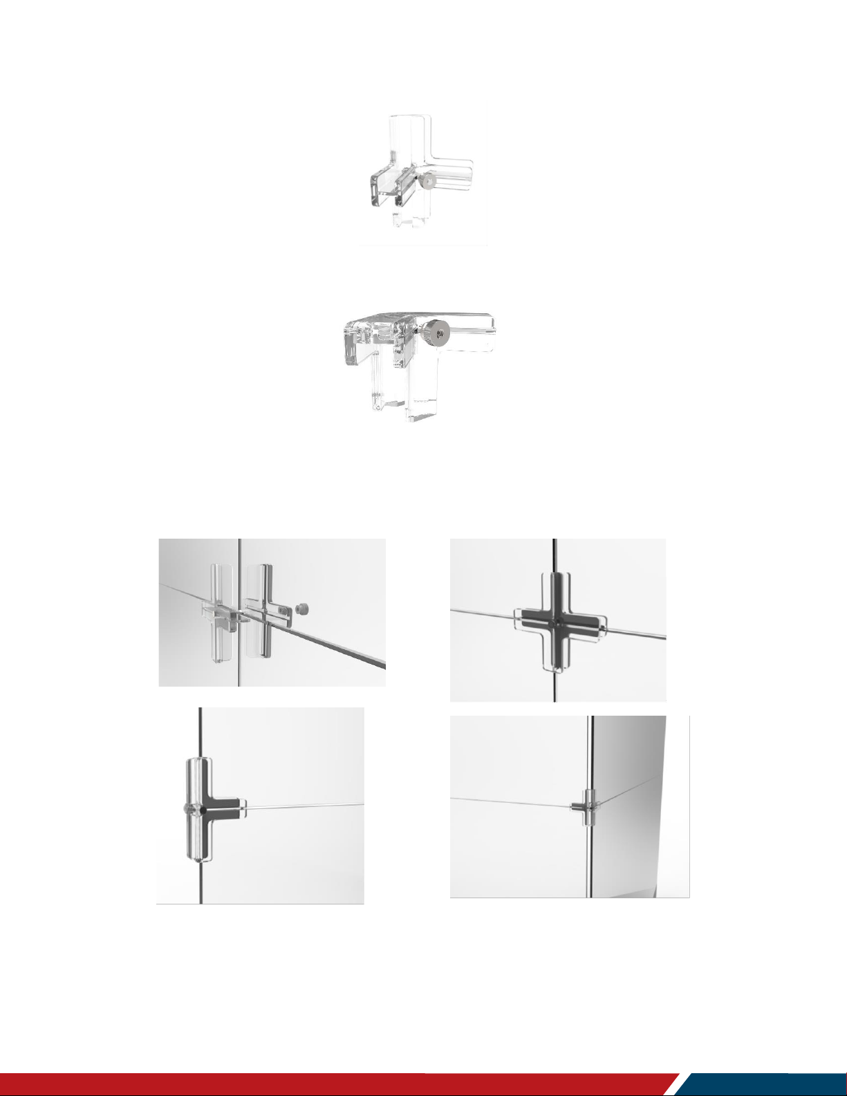
Cross sign shape for right angle (2x2 Panels)
T-shape for right angle (2x1). This is recommended for use in Nx1 landscape right angle installations or
to terminate tiled portrait mode systems.
Refer to the “Multiple Displays” section on page 22 for proper use. Examples of Tiling
Hardware usage is illustrated in the figures below:
Page 18
Planar LookThru Transparent OLED Display User Manual
020-1380-00
Page | 18
Tour of the Planar LookThru Transparent OLED Product Family
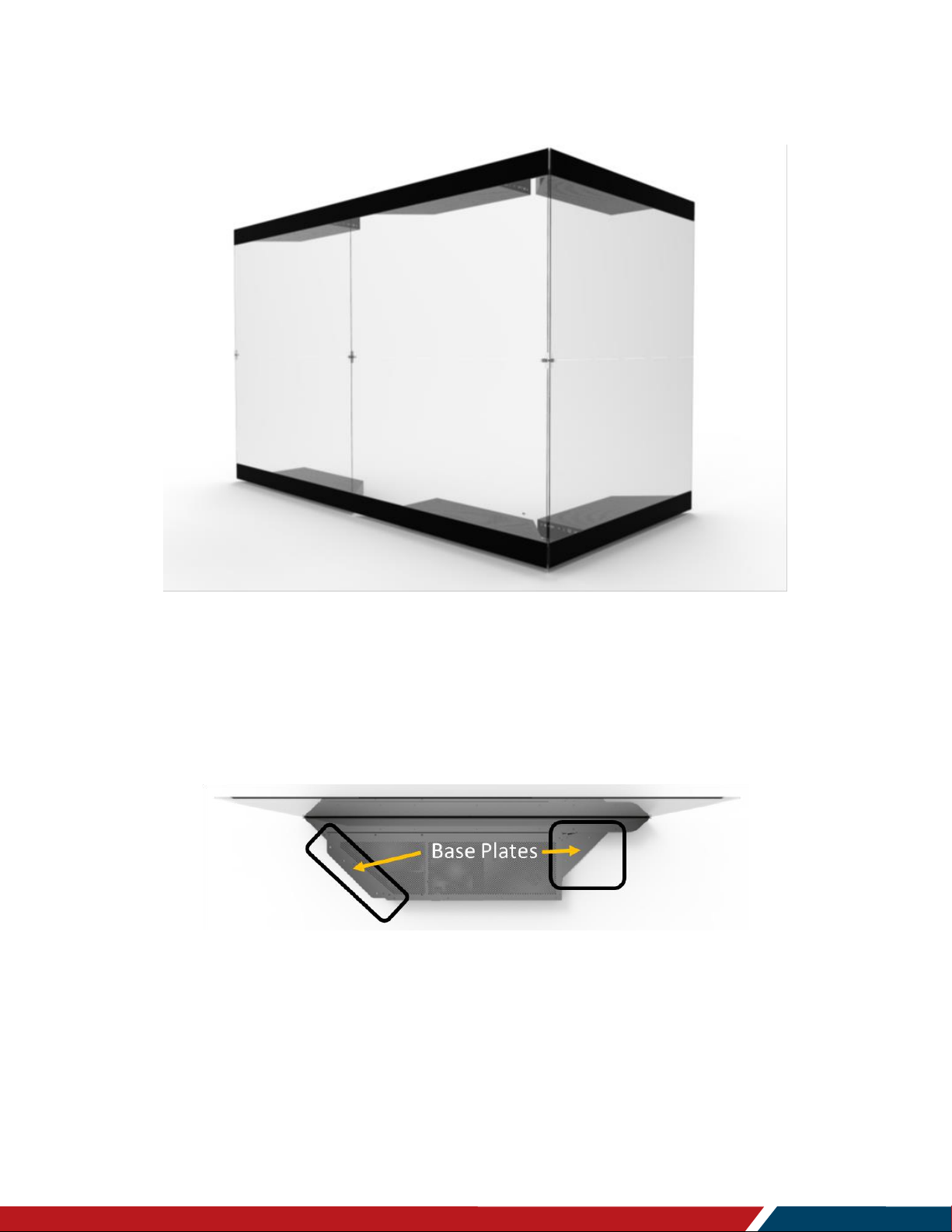
Here is an example of a tiled LO552 installation showing use of the Tiling Hardware:
Base Plates
The Base Plates are used with the Planar LookThru LO552 (standard version) for ceiling,
wall or tabletop mounting. Base Plates support either landscape or portrait orientation
and doesn’t restrict airflow through the perforations in the electronic box. The placement
of the mounting holes in the mounting plates accommodate 16 inch centers. With the use
of connecting plates, the Base Plates can attached to an adjacent display. See the top
and bottom views in the figures below.
Page 19
Planar LookThru Transparent OLED Display User Manual
020-1380-00
Page | 19
Unpacking and Installing the Display
Unpacking and Installing
the Display
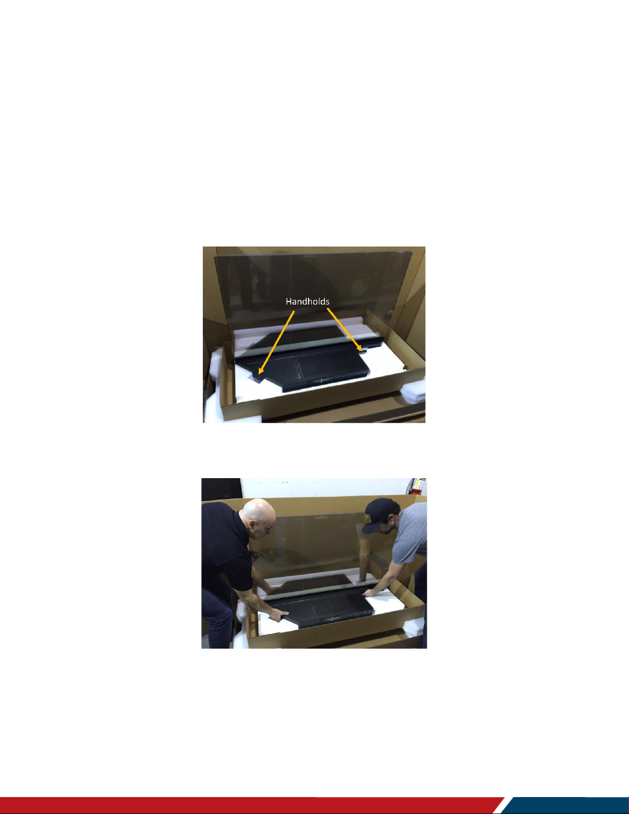
6. Safe Handling
When removing the display from its shipping box, use the indicated handhold
locations shown in the picture below. Also grip the underside of the Display Glass in
lifting the display from the shipping box.
We recommend the display be handled by at least two people. At no time should the
glass be held where the weight of the display is borne by the glass. Proper handling
is demonstrated in the picture below.
Be certain any surface where the display(s) will be placed can safely support the
70 lbs (31.8 kg) weight of the display.
We recommend using the shipping box for transport whenever possible.
Page 20

Planar LookThru Transparent OLED Display User Manual
020-1380-00
Page | 20
Unpacking and Installing the Display
7. Environmental Considerations
The Planar LookThru LO552 is intended for indoor use only.
Displays should only be installed in an environment where the temperature and
humidity are kept within the proper use range. See the Environmental Specifications
on page 61.
Planar LookThru LO552 displays should not be operated on a carpet that can stifle
ventilation through the perforations in the underside of the electronic box.
Planar LookThru LO552 displays are not designed to be sunlight readable.
Do not locate the displays in direct sunlight or where the Display Glass will be
exposed to ultraviolet (UV) light.
The electronic box should not be located near heat sources or in an environment
where there is less than 0.47 inches (12 mm) of free space on all sides. Note that the
Display Glass and the Display Chassis do not rise in temperature much above
ambient during operation.
For best use of the display transparency, make certain there is adequate illumination
in the space behind the screen so that items of interest can be viewed optimally
through the display. We recommend experimenting with the level and orientation of
the illumination.
8. Installation Disclaimer
Proper installation of the display is the responsibility of the end customer. Failure to
follow the safety and installation instructions in this manual, Content Developer’s Guide
or Fabricator’s Guide, or any installation of the display in a manner not described in this
manual, Content Developer’s Guide or Fabricator’s Guide, may result in damage to the
display or unsafe conditions, which will not be covered by the product warranty.
9. Requirements for All Installations
Make sure the surface or structure where the display is to be mounted is capable of
supporting the weight of the display or displays to be used. Consult the “Specifications”
section on page 61 for weights and measures.
If the display is to be attached to a surface or structure, use the five M6 mounting points
in the Display Chassis as the primary attachment point. The mounting holes in the
electronic box employed can provide supplementary support but should not be used for
mounting by themselves. No fewer than three of primary mounting holes should be used
in any installation.
Make sure the Display Glass maintains a neutral position and is not loaded in any way.
The front Display Glass surfaces should be mounted straight and plumb, i.e.
perpendicular to the horizontal in all axes.
Page 21
Planar LookThru Transparent OLED Display User Manual
020-1380-00
Page | 21
Unpacking and Installing the Display
For mounting a Planar LookThru LO552, the leveling feet and counterweight must be
removed. Using two people, we recommend carefully laying the Display Glass on a
suitable countertop with a soft surface with the electronic box perpendicular to the
counter. The leveling feet and counterweight can then be removed safely.
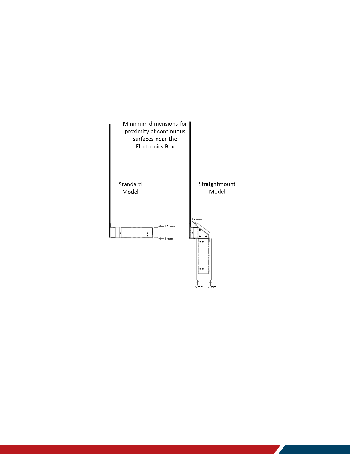
The perforations in the electronic box are a part of the thermal management system and
should never be covered or have any solid surface be located closer than what is defined
in the figure below. This keep-out restriction does not apply under or on top of the Display
Chassis.
We do not recommend that the Straight Mount Model be mounted where the weight of
the display is carried by the bottom surface of the electronic box.
Page 22

Planar LookThru Transparent OLED Display User Manual
020-1380-00
Page | 22
Unpacking and Installing the Display
10. Multiple Displays
In an installation where one or more displays are mounted above one another, make
certain each display is mounted independently. The weight of a display or displays
mounted above another should not be borne by the lower display.
The Display Glass must be properly aligned and plumb before attachment of the tiling
hardware. The tiling hardware should not be used to bring the Display Glass into
alignment. This will create a permanent load on the glass. Shim and adjust placement of
the display at the mounting points to bring the glass into proper position.
Do not overtighten the tiling hardware.
Page 23

Planar LookThru Transparent OLED Display User Manual
020-1380-00
Page | 23
Operating the Display
Operating the Display
11. OSD Keypad
Keypad
Page 24

Planar LookThru Transparent OLED Display User Manual
020-1380-00
Page | 24
Operating the Display
12. OSD Keypad Buttons
Key
Descriptions
Power
Power on/Power off
Menu Left/Decrease value
Menu Right/Increase value
Menu Up/Increase volume
Menu Down/Decrease volume
Menu
Menu/Exit
SRC
Source selection (toggle)
13. Using the Remote Control
The Remote Control included with every Planar LookThru LO552 model is shown below.
An IR sensor is located beneath the perforated cover in the back center of the electronic
box. The shaded triangles in the figures below indicate the approximate range of
coverage of that sensor. Note this includes access through the front side of the glass.
Page 25

Planar LookThru Transparent OLED Display User Manual
020-1380-00
Page | 25
Operating the Display
Each remote control is shipped with the same identification code, 01785. To change this
code so, for example, individual displays can be controlled separately, the
reprogramming process follows. Both the display and the remote control need to be
programmed:
13.1 Display
1. Navigate to Advanced Settings > System Settings > IR Remote Code.
2. Press the Enter key to start editing the code.
3. Using the numeric keypad on the remote, enter a new code (max value is 0xFFF or
65,535).
4. Press the Enter key to confirm the entry.
13.2 Remote Control
1. On the IR Remote, hold down the Code key for 5 seconds. The red LED on the
remote should turn on and remain on.
2. Enter the same code that was entered on the display (including leading zeros).
3. Once five digits have been entered, the LED should turn off. The remote has been
programmed.
Comments
The RS-232 command “IR.Code=XXXXX” may also be used to program the display
only.
If a valid code is not entered and no keys are pressed for 30 seconds, the light will
turn off and the remote will exit programming mode
To expand the coverage of the remote control, an IR sensor with a 112-inch
(2850 mm) long cable is included with every LO552 model, shown on the
right. The phone jack plugs into the port marked “IR” on the perpendicular
backside of the display.
13.3 External Control
In addition to using the Planar remote control and keypad, there are other
methods of controlling the Planar LookThru LO552 display externally:
Using a serial link to send ASCII commands and to receive responses to
those commands. The same set of commands can be sent over RS 232,
TCP or UDP. See the Planar LookThru RS232 User Manual for more details.
Using the discrete infrared (IR) codes to program a third-party remote control. See
the “IR Command Protocol” section, next.
Page 26

Planar LookThru Transparent OLED Display User Manual
020-1380-00
Page | 26
IR Command Protocol
IR Command Protocol
The Planar LookThru displays accept commands in the form of IR signals that conform to
the NEC protocol. Each Planar LookThru remote control has an NEC control code
associated with it. These codes can be used to program a third-party “universal” remote
control to work with the Planar LookThru displays. These third-party products usually
come with a computer software application for this purpose. For more information, consult
the documentation provided with the remote control.
The IR control codes hav e the following characteristics:
Each code consists of the following:
A leader pulse (a modulated pulse of 9 ms followed by a non-modulated pulse of
4.5 ms)
16 address bits. The default address is 1785 (0x06F9, binary 00000110
11111001)
16 data bits: eight (8) bits for the command followed by the logical inverse of the
command
An end pulse (a modulated pulse of 0.56 ms, similar to the modulated pulse in
the ‘0’ and ‘1’ bits). The end of the modulated pulse constitutes the end of the
data transmission.
The carrier frequency is 38 kHz, with the modulated pulses having a 33% duty cycle.
Commands are sent at a maximum rate of 9 Hz.
For example, below is the NEC control code for the ON button of the Planar LookThru
remote control (assuming the default address is used).
Hex
06
F9
01
FE
Binary
00000110
11111001
00000001
11111110
Function
Address Byte
1
Address Byte
2
Command
Command (Logical
Inverse)
Leader Pulse
0 0 0 0 0 01 19 ms 4.5 ms
Address Byte 1 Address Byte 2 Command Byte Command Byte (logical inverse)
0 0 0 0 0 0 0 0 0 01 1 1 1 1 1 1 1 1 1 1 1 1 1
End Pulse
13.5 ms 27 ms 27 ms
Page 27

Planar LookThru Transparent OLED Display User Manual
020-1380-00
Page | 27
IR Command Protocol
Remote
Control
Button Name
Address
Data
NEC Data From
Remote (Hex Code)
Description
ON
1785
1
0x06F901FE
Power on
OFF
1785
9
0x06F909F6
Power off
1785
2
0x06F902FD
Not used
1785
3
0x06F903FC
Not used
**
1785
6
0x06F906F9
Not used
PRESETS
1785
4
0x06F904FB
Opens the Presets menu
PRESET 1
1785
5
0x06F905FA
Applies Preset 1
PRESET 2
1785
7
0x06F907F8
Applies Preset 2
PRESET 3
1785
8
0x06F908F7
Applies Preset 3
PRESET 4
1785
10
0x06F90AF5
Applies Preset 4
1
1785
12
0x06F90CF3
Number button 1
2
1785
13
0x06F90DF2
Number button 2
3
1785
14
0x06F90EF1
Number button 3
4
1785
15
0x06F90FF0
Number button 4
5
1785
16
0x06F910EF
Number button 5
6
1785
17
0x06F911EE
Number button 6
7
1785
20
0x06F914EB
Number button 7
8
1785
25
0x06F919E6
Number button 8
9
1785
27
0x06F91BE4
Number button 9
0
1785
18
0x06F912ED
Number button 0
VOL +
1785
28
0x06F91CE3
Volume increase
VOL -
1785
33
0x06F921DE
Volume decrease
MUTE
1785
32
0x06F920DF
Audio mute
COLOR
1785
19
0x06F913EC
Not used
VIDEO WALL
1785
34
0x06F922DD
Not used
MISC
1785
11
0x06F90BF4
Not used
MENU
1785
21
0x06F915EA
Opens the menu
PREV
1785
22
0x06F916E9
Returns to the previous menu
ENTER
1785
23
0x06F917E8
Selects the current menu item
UP
1785
26
0x06F91AE5
Navigate up
DOWN
1785
29
0x06F91DE2
Navigate left
LEFT
1785
31
0x06F91FE0
Navigate right
Page 28

Planar LookThru Transparent OLED Display User Manual
020-1380-00
Page | 28
IR Command Protocol
Remote
Control
Button Name
Address
Data
NEC Data From
Remote (Hex Code)
Description
RIGHT
1785
24
0x06F918E7
Navigate down
TOP
1785
30
0x06F91EE1
Selects the top line in the current
menu
ZONE 1
1785
35
0x06F923DC
Selects the input for Zone 1
ZONE 2
1785
36
0x06F924DB
Selects the input for Zone 2
ZONE 3
1785
38
0x06F926D9
Selects the input for Zone 3
ZONE 4
1785
39
0x06F927D8
Selects the input for Zone 4
PIP MODE
1785
37
0x06F925DA
Selects the Multi-Source View
setting
PIP SWAP
1785
40
0x06F928D7
Swaps the main and PIP windows
HDMI 1
1785
41
0x06F929D6
Selects HDMI 1 for the current
zone
HDMI 2
1785
42
0x06F92AD5
Selects HDMI 2 for the current
zone
HDMI 3
1785
43
0x06F92BD4
Selects HDMI 3 for the current
zone
HDMI 4
1785
44
0x06F92CD3
Selects HDMI 4 for the current
zone
DP
1785
45
0x06F92DD2
Selects DP for the current zone
DVI
1785
46
0x06F92ED1
Not used
VGA
1785
47
0x06F92FD0
Not used
OPS
1785
48
0x06F930CF
Not used
14. Locking the Keypad and IR Remote
The keypad and IR remote functionality can be locked on the display. To lock the keypad,
go to Main Menu > Advanced Settings > System Settings and select Keypad Lock.
To lock the IR remote, go to Main Menu > Advanced Settings > System Settings and
select IR Remote Lock.
15. Unlocking the Keypad and IR Remote
To unlock the keypad, press the following keys on the keypad in the order listed: UP, UP,
RIGHT, LEFT, DOWN. If the IR remote is unlocked, the keypad can also be unlocked by
using the IR remote to go to Main Menu > Advanced Settings > System Settings and
unchecking Keypad Lock.
To unlock the IR remote, press the following keys on the IR remote in the order listed: UP,
UP, RIGHT, LEFT, DOWN. If the keypad is unlocked, the IR remote can also be unlocked
Page 29

Planar LookThru Transparent OLED Display User Manual
020-1380-00
Page | 29
IR Command Protocol
by using the keypad to go to Main Menu > Advanced Settings > System Settings and
unchecking IR Remote Lock.
16. Turning the Display On
1. Insert the power cord in to the display and into the power outlet.
2. Ensure the AC switch is set to “ “.
3. Press the ON button on the remote or the power button on the keypad.
4. The Planar splash screen should appear within about 15 seconds.
Note: If the Power Saving Mode is enabled and no digital input is connected, the display
will wait for the delay specified in the Power section of the OSD and turn the display off.
This will occur until a digital input is established. See the “Power Submenu” section on
page 40 for more details.
17. Turning the Display Off
The display should always be turned off by either the remote or keypad power button to
extend the life of the display. An image optimization algorithm to keep the image in peak
performance is initiated at power off and can take up to 3 minutes to complete after the
power button is pressed. This algorithm is run after the display has been on for more than
four hours. Indication that the power may be removed from is the display status light will
be solid green.
18. Image Optimization Algorithms
There are two image optimization procedures that may be run on the display to keep the
image operating in peak performance.
1. The first is an automatic process that runs when the power button on the remote or
keypad is used to power off the system. The process will run after four hours of
cumulative display uptime and may take up to three minutes to complete. If power is
removed from the system before or during the process, the optimization will run the
next time the power button is used. The display status indicator will indicate the
optimization is in process by blinking amber and indicate complete when solid green.
2. The second is an automatic process that runs when the display is turned on after a
cumulative uptime of 2000 hours. This is performed after the previous optimization
and may take up to 20 seconds of additional boot time. Power should not be
removed during this process. The display status indicator will indicate the
optimization is in process by blinking green and indicate complete when solid amber.
Page 30

Planar LookThru Transparent OLED Display User Manual
020-1380-00
Page | 30
IR Command Protocol
19. LED Indicators
The LED indicator light is visible under the perforated cover for the electronic box, near
the right angle corner. The approximate location is identified by the arrow in the figure
below.
The table below indicates what the different LED Indicator colors and blink pattern mean.
LED On
Power Status
Condition
Green
Standby mode
Amber
Full power mode
Green Flashing (1 Hz)
AC power on
Green Flashing (0.5 Hz)
Powering on from standby
Green Flashing (5 Hz)
Firmware updating
Amber Flashing (5 Hz)
Power supply failure
Green and Amber
Firmware update failure
Page 31

Planar LookThru Transparent OLED Display User Manual
020-1380-00
Page | 31
Navigating Through the Menus
Navigating Through the
Menus
1. With the power on, press MENU. The MAIN menu appears.
2. Within the menu, use , , , and ENTER to navigate through the menus and
adjust options.
3. Press PREV on the remote control, or MENU on the keypad, to return to the previous
menu. To exit the menu system, press MENU on the remote control, or continue to
press MENU on the keypad until the main menu is reached.
Page 32

Planar LookThru Transparent OLED Display User Manual
020-1380-00
Page | 32
Navigating Through the Menus
20. Inputs and Views Menu
This menu shows how the sources will be laid out on the screen based on the current
Multi-Source View and Advanced Layouts selections.
Multi-Source View
Select the Multi-Source View mode
Options: Single, Dual, Triple, Quad, PIP; Default: Single
Note: For the Advanced Layouts submenu, refer to page 33.
Note: 4K/60Hz can only be used in Single mode.
Zone 1
Select the source displayed in Zone 1
Options: HDMI 1, HDMI 2, HDMI 3, HDMI 4, DP; Default: HDMI 1
Zone 2
Select the source displayed in Zone 2
Options: HDMI 1, HDMI 2, HDMI 3, HDMI 4, DP; Default: HDMI 2
Zone 3
Select the source displayed in Zone 3
Options: HDMI 1, HDMI 2, HDMI 3, HDMI 4, DP; Default: HDMI 3
Zone 4
Select the source displayed in Zone 4
Options: HDMI 1, HDMI 2, HDMI 3, HDMI 4, DP; Default: HDMI 4
Auto Scan Sources
Select whether the display will automatically scan for a valid source on any zone that
currently does not have a source
Options: On, Off; Default: Off
Page 33

Planar LookThru Transparent OLED Display User Manual
020-1380-00
Page | 33
Navigating Through the Menus
20.1 Advanced Layouts Submenu
This submenu defines the layouts for each multi-source view type.
Dual
Select from two dual source layout options. The layout in orange will be the active
layout displayed when the Multi-Source View is set to Dual.
Triple
Select from five triple source layout options. The layout in orange will be the active
layout displayed when the Multi-Source View is set to Triple.
PIP
Select from four PiP (Picture-in-Picture) layouts. The layout in orange will be the
active layout displayed when the Multi-Source View is set to PiP.
PIP Size
Select the size of the PiP (Picture-in-Picture) window.
Page 34

Planar LookThru Transparent OLED Display User Manual
020-1380-00
Page | 34
Navigating Through the Menus
21. Image Adjust Menu
This menu is used for making common image adjustments for the current zone.
Current Zone
The zone that is currently being adjusted. All of the settings in this menu are saved
per input. The zone’s corresponding input source is shown in the title bar, and the
graphic beneath that shows which zone is being adjusted in the current Multi-Source
View mode and Advanced Layout setting (if applicable).
The current zone can be changed via the menu or by using the ZONE 1-4 keys on
the remote control.
Note: Changing the Current Zone setting also changes the Audio Select setting.
Brightness
Adjust the brightness value of the image
Range: 0~100; Default: 50
Contrast
Adjust the contrast of the image
Range: 0~100; Default: 50
Page 35

Planar LookThru Transparent OLED Display User Manual
020-1380-00
Page | 35
Navigating Through the Menus
Color
Adjust the saturation of the image
Range: 0~100; Default: 50
Tint
Adjust the hue of the image
Range: 0~100; Default: 50
Sharpness
Adjust the sharpness of the image. Higher numbers are sharper
Range: 0~10; Default: 5
Noise Reduction
Turn on noise reduction processing
Options: Off, Low, Medium, High; Default: Off
Diagnostic Color
Set the image to monochrome. This setting is for use in adjustments to a test pattern
and is not stored.
Options: Off, Red, Green, Blue; Default: Off
Color Space
Set the color space of the image
Options: REC601, REC709, RGB, RGB Video, Auto; Default: Auto
Color Temperature
Set the color temperature of the image
Options: 3200K, 5500K, 6500K, 7500K, 9300K, Native; Default: Native
Red Gain
Adjust the red gain of the image
Range: 0~200; Default: 100
Green Gain
Adjust the green gain of the image
Range: 0~200; Default: 100
Blue Gain
Adjust the blue gain of the image
Range: 0~200; Default: 100
Page 36

Planar LookThru Transparent OLED Display User Manual
020-1380-00
Page | 36
Navigating Through the Menus
Red Offset
Adjust the red offset of the image
Range: 0~100; Default: 50
Green Offset
Adjust the green offset of the image
Range: 0~100; Default: 50
Blue Offset
Adjust the blue offset of the image
Range: 0~100; Default: 50
Gamma
Set the gamma of the image
Options: 1.5, 1.55, 1.6, 1.65, 1.7, 1.75, 1.8, 1.85, 1.9, 1.95, 2.0, 2.05, 2.1, 2.15, 2.2,
2.25, 2.3, 2.4, 2.45, 2.5, 2.55, 2.6, 2.65, 2.7, 2.75, 2.8
Default: 2.2
Aspect Ratio
Set how the source is treated when the aspect ratio of the input is different than the
aspect ratio of the zone it is in. If the image does not fill the zone completely, the
extra margins are black.
Options: Auto, 16:9, 4:3, Fill Screen, Native, Letterbox; Default: Auto
Overscan
Set the percentage of the image to remove from each edge
Range: 0~20; Default: 0
Image Position
Move the image horizontally or vertically. The amount to move is measured in input
pixels.
Range: -1000~1000; Default: 0
Page 37

Planar LookThru Transparent OLED Display User Manual
020-1380-00
Page | 37
Navigating Through the Menus
22. Audio Menu
This menu adjusts the audio for the selected zone.
Audio Select
The zone that is currently being adjusted and whose audio is being played. All of the
settings in this menu are saved per input. The zone’s corresponding input source is
shown in the title bar.
Options: Zone 1, Zone 2, Zone 3, Zone 4; Default: Zone 1
Note: Changing the Audio Select setting also changes the Current Zone setting.
Volume
Set the volume of the audio
Range: 0~100; Default: 50
Balance
Set the audio balance
Range: 0~100; Default: 50
Mute
Mute or unmute the audio
Options: On or Off; Default: Off
Page 38

Planar LookThru Transparent OLED Display User Manual
020-1380-00
Page | 38
Navigating Through the Menus
23. Presets Menu
This menu saves Inputs and Views settings, Image Adjust settings, Audio settings, the
Backlight Intensity setting, and the Local Dimming setting. Up to 10 presets can be saved
using this menu (more can be saved via the serial command interface). If a preset is
saved, it will appear as “Preset 1”, “Preset 2”, and so on. If it is not saved, it will appear
as “<Empty>”.
Recall
Apply the setup from the selected preset
Range: Preset 1~Preset 10
Save
Save the current setup for later recall
Range: Preset 1~Preset 10
Delete
Delete the selected preset
Range: Preset 1~Preset 10
Page 39

Planar LookThru Transparent OLED Display User Manual
020-1380-00
Page | 39
Navigating Through the Menus
24. Advanced Settings Menu
24.1 Panel Brightness Submenu
Intensity
Adjusts relative brightness of the panel
Range: 0 to 100%
Page 40

Planar LookThru Transparent OLED Display User Manual
020-1380-00
Page | 40
Navigating Through the Menus
24.2 Power Submenu
Auto Power On
Set whether the system will automatically leave standby mode after AC power is
applied
Options: On, Off; Default: Off
Power Saving Mode
Set the action to take if there is no signal detected after the period of time selected
by the Power Saving Delay setting:
Disabled: The display will remain on even if no signal is present.
Low Power: The display will enter standby mode if no signal is detected after the
specified period of time.
Wake on Signal: The display will enter a reduced power mode if no signal is
detected after the specified period of time. When in this state, the display will turn
on when a signal is detected or when any key is pressed on the keypad or IR
remote.
Power Saving Delay
Set the number of minutes to delay before initiating the power saving mode action (if
any)
Options: 1 Minute, 5 Minutes, 15 Minutes, 30 Minutes, 60 Minutes; Default: 5
minutes
Power On Delay
Postpones startup by the set amount
Range: 0 to 10 seconds in 0.1 second increments
Page 41

Planar LookThru Transparent OLED Display User Manual
020-1380-00
Page | 41
Navigating Through the Menus
24.3 Network Submenu
The default static IP values are:
IP Address: 192.168.12.12
Subnet Mask: 255.255.255.0
Default Gateway: 192.168.12.1
The static IP settings that are programmed will be used if a DHCP server cannot be
found.
MAC Address
The MAC address of the system
IP Address
The current network address. Use the number keys on the remote to enter this
information.
Subnet Mask
The current subnet mask. Use the number keys on the remote to enter this
information.
Default Gateway
The current default gateway. Use the number keys on the remote to enter this
information.
DNS Server
The current DNS server. Use the number keys on the remote to enter this
information.
Note: The specified DNS server is used when Use Network Time is checked for the
Set Date and Time setting.
DHCP
Turn DHCP on or off
Options: On, Off; Default: On
Page 42

Planar LookThru Transparent OLED Display User Manual
020-1380-00
Page | 42
Navigating Through the Menus
24.4 Menus and Messages Submenu
Menu Position
Move the OSD menu to a different location on the screen
Options: Center, Upper Left, Upper Right, Lower Left, Lower Right; Default: Center
OSD Transparency
Set the transparency of the OSD so that the image behind it can be seen. Higher
values mean greater transparency.
Range: 0~5; Default: 0
OSD Timeout
Set the amount of time in seconds since the last keypress before the OSD menu
automatically closes. If set to Off, the menu never automatically closes.
Options: Off, 10 Seconds, 30 Seconds, 60 Seconds, 120 Seconds, 240 Seconds;
Default: 60 Seconds
Allow Pop Up Messages
Suppress messages that pop up automatically. When set to No, the source status
message and the volume slider bar will not be displayed.
Options: Yes or No; Default: Yes
Allow Splash Screen
Enable or disable the splash screen during startup
Options: Enable or Disable; Default: Enable
OSD Rotation
Rotate the OSD menu so that it is readable if the display is mounted in portrait
orientation
Options: Landscape or Portrait; Default: Landscape
Blank Screen Color
Select the color to display when there is no signal in a zone
Options: Black, White, Gray, Red, Green, Blue, Cyan, Magenta, Yellow
Default: White
Page 43

Planar LookThru Transparent OLED Display User Manual
020-1380-00
Page | 43
Navigating Through the Menus
24.5 Schedule Submenu
Set Date and Time
Set the internal system clock. If Use Network Time is unchecked, the following
settings can be set individually: Time Zone, Year, Month, Day, Date, Hour, and
Minute.
Note: If Use Network Time is checked and DHCP is unchecked, the display will be
unable to obtain the network time unless a DNS server is programmed. This is done
via the DNS Server setting in the Network menu or the serial command interface.
Page 44

Planar LookThru Transparent OLED Display User Manual
020-1380-00
Page | 44
Navigating Through the Menus
Set Event 1~Event 20
Event Enabled: Turns on the event. If disabled, the settings are saved so that the
event can be re-enabled.
Frequency: The frequency of the event. Options are Daily, Weekly, Weekdays,
Weekends.
Action: The action to take for the event. Options are Turn On, Turn Off, Recall,
Backlight.
Data: The preset to recall when the Action is set to Recall, or the backlight setting
when the Action is set to Backlight.
Page 45

Planar LookThru Transparent OLED Display User Manual
020-1380-00
Page | 45
Navigating Through the Menus
24.6 EDID Submenu
This menu specifies the EDID format and preferred timing for the selected connector.
Selected Connector
Set which connector is used
Options: HDMI 1, HDMI 2, HDMI 3, HDMI 4, DP, OPS, All
Program EDID
Program the EDID information for the selected connector based on the selections in
the EDID submenu
EDID Type
Set the EDID type to determine the base EDID used for the current connector:
4K60 selects an EDID format compliant with HDMI 2.0 and DP 1.2
4K30 selects an EDID format compliant with HDMI 1.4b and DP 1.1
1080P selects an EDID format compliant with HDMI 1.3 and DP 1.1
Options: 4K60, 4K30, 1080P
Horizontal Active
The number of active pixels in a line
Range: 0~4095
Page 46

Planar LookThru Transparent OLED Display User Manual
020-1380-00
Page | 46
Navigating Through the Menus
Vertical Active
The number of active lines in a field
Range: 0~4095
Vertical Refresh Rate
The number of fields per second rounded to the nearest Hz
Range: 0~120
Fully Specified
Determine how the final detailed timing is calculated. If disabled, it is calculated
based on Horizontal Active, Vertical Active, and Vertical Refresh Rate values. If
enabled, it is calculated based on all of the EDID values except for Vertical Refresh
Rate.
Options: Disabled, Enabled
Note: This setting should only be enabled by advanced users.
Pixel Clock
The value of the pixel clock, in megahertz
Range: 0~60000
Horizontal Blanking
The number of non-active pixel clocks in a line
Range: 0~1023
Horizontal Front Porch
The number of pixel clocks in the horizontal front porch
Range: 0~1023
Horizontal Sync Width
The number of pixel clocks in the horizontal sync pulse
Range: 0~255
Vertical Blanking
The number of non-active lines in a field
Range: 0~255
Page 47

Planar LookThru Transparent OLED Display User Manual
020-1380-00
Page | 47
Navigating Through the Menus
Vertical Front Porch
The number of line times in the vertical front porch
Range: 0~255
Vertical Sync Width
The number of line times in the vertical sync
Range: 0~255
Revert to Factory
Reset the EDID type and timings to the default values for the selected connector
Page 48

Planar LookThru Transparent OLED Display User Manual
020-1380-00
Page | 48
Navigating Through the Menus
25. Tiling
Tiling Enabled
Turns tiling on or off
Wall Width
Indicates the number of displays in the horizontal
Wall Height
Defines the number of displays in the vertical
Unit Column
Defines the horizontal address of the display within the titled wall
Unit Row
Defines the vertical address of the display within the tiled wall
Frame Compensation
Turns frame compensation on or off
Frame Width
Defines the amount of frame compensation on the left and right side of the content
Frame Height
Defines the amount of frame compensation on the top and bottom of the content
Page 49

Planar LookThru Transparent OLED Display User Manual
020-1380-00
Page | 49
Navigating Through the Menus
25.1 Comments about Frame Compensation
When video displays are used in an array, the intent is to display a large version of an
image. However, even the tiniest of mullions can break up the image oddly. Notice the
eagle’s eye here.
One way around this is to adjust the image spacing between displays. Imagine looking
out a window made up of many panes of glass. The image seen is partially obscured by
the frames (mullions), but the visual system assembles the image and ignores the bars.
Note: Frame compensation is also known a mullion or bezel compensation.
Page 50

Planar LookThru Transparent OLED Display User Manual
020-1380-00
Page | 50
Navigating Through the Menus
25.2 System Settings Submenu
Enable Status LED
Turns on status LEDs
Pixel Orbit
Turns on pixel orbit. This moves the entire screen randomly by up to 10 pixels to
lessen the onset of burn in.
Inverted Mount
Rotates the OSD when an inverted mount is used
IR Remote Code
Identifies the remote code address used. Refer to the IR Command Protocol section
DisplayPort Type
Set the version of DisplayPort that is used by the system
Options: 1.1, 1.2; Default: 1.2
Keypad Lock
Lock or unlock the keypad. When it is enabled, all keypad presses will be ignored.
Options: Enable, Disable; Default: Disable
IR Remote Lock
Lock or unlock the remote control. When it is enabled, all remote control presses will
be ignored.
Options: Enable, Disable; Default: Disable
Factory Reset
Return the saved settings in a system to their factory defaults
Firmware Update
Update the firmware for the display. Refer to the instructions on the firmware release
package for more information.
Page 51

Planar LookThru Transparent OLED Display User Manual
020-1380-00
Page | 51
Navigating Through the Menus
26. Information Menu
26.1 System Information Submenu
This menu displays version information for all programmable parts in the system. It also
contains the model and serial number.
26.2 Image Information Submenu
This menu displays image details for the current zone. If more than one zone is available,
the zones can be changed by setting the Current Zone option.
Page 52

Planar LookThru Transparent OLED Display User Manual
020-1380-00
Page | 52
Navigating Through the Menus
26.3 Error Log Submenu
This menu displays a chronological list of system errors that have occurred.
Page 53

Planar LookThru Transparent OLED Display User Manual
020-1380-00
Page | 53
Developing Content
Developing Content
We strongly recommend using the Planar LookThru OLED Transparent Display Content
Developer’s Guide at http://www.planar.com/products/transparent-displays/oled/. Use of
this guide will both enhance the viewing experience of Planar LookThru LO552 users and
maximize the life of the display.
Page 54

Planar LookThru Transparent OLED Display User Manual
020-1380-00
Page | 54
Signal Compatibility
Signal Compatibility
Signal
Type
Resolution
Frame rate
(Hz)
Line Rate
(kHz)
Pixel Rate
(MHz)
HDMI 1
-2
HDMI 3
-4 + OPS
DisplayPort
References
PC
640x480
59.94
31.469
25.175
x x x
VESA DMT, CEA-861-F
Format 1
640x480
72
37.861
31.500
x x x
VESA DMT
640x480
74.99
37.500
31.500
x x x
VESA DMT
640x480
85
43.269
36.000
x x x
VESA DMT
800x600
60.32
37.890
40.000
x x x
VESA DMT
800x600
72
48.077
50.000
x x x
VESA DMT
800x600
75
46.875
49.500
x x x
VESA DMT
800x600
85.06
53.674
56.250
x x x
VESA DMT
848x480
59.659
29.830
31.500
x x x
VESA CVT
848x480
74.769
37.684
41.000
x x x
VESA CVT
848x480
84.751
42.969
46.750
x x x
VESA CVT
1024x768
60
48.363
65.000
x x x
VESA DMT
1024x768
70
56.476
75.000
x x x
VESA DMT
1024x768
75.03
60.023
78.750
x x x
VESA DMT
1024x768
85.03
68.677
94.500
x x x
VESA DMT
1152x864
70.012
63.851
94.500
x x x
VESA DMT
1152x864
75
67.500
108.000
x x x
VESA DMT
1152x864
84.999
77.094
121.500
x x x
VESA DMT
1280x768
49.929
39.593
65.250
x x x
VESA CVT
1280x768
59.995
47.396
68.250
x x x
VESA CVT-R
Page 55

Planar LookThru Transparent OLED Display User Manual
020-1380-00
Page | 55
Signal Compatibility
Signal
Type
Resolution
Frame rate
(Hz)
Line Rate
(kHz)
Pixel Rate
(MHz)
HDMI 1
-2
HDMI 3
-4 + OPS
DisplayPort
References
PC
1280x768
60
47.776
79.500
x x x
VESA CVT
1280x768
74.893
60.289
102.250
x x x
VESA CVT
1280x768
84.837
68.633
117.500
x x x
VESA CVT
1280x960
60
60.000
108.000
x x x
VESA DMT
1280x960
75
75.000
126.000
x x x
VESA DMT
1280x960
85.002
85.938
148.500
x x x
VESA DMT
1280x1024
60.02
63.981
108.000
x x x
VESA DMT
1280x1024
75.02
79.976
135.000
x x x
VESA DMT
1280x1024
85.02
91.146
157.500
x x x
VESA DMT
1360x768
60
47.712
85.500
x x x
VESA DMT
1400x1050
49.965
54.113
100.000
x x x
VESA CVT
1400x1050
60
64.7
101.00
x x x
VESA CVT-R
1400x1050
60
65.317
121.750
x x x
VESA CVT
1400x1050
74.867
82.278
156.000
x x x
VESA CVT
1600x1200
60
75.000
162.000
x x x
VESA DMT
1920x1080
49.929
55.621
141.500
x x x
VESA CVT
1920x1080
59.963
67.158
173.000
x x x
VESA CVT
1920x1080
59.950
66.587
138.500
x x x
VESA CVT-R
1920x1200
49.932
61.816
158.250
x x x
VESA CVT
1920x1200
59.950
74.038
154.000
x x x
VESA CVT-R
1680x1050
49.974
54.121
119.500
x x x
VESA CVT
1680x1050
59.954
65.290
146.250
x x x
VESA CVT
Page 56

Planar LookThru Transparent OLED Display User Manual
020-1380-00
Page | 56
Signal Compatibility
Signal
Type
Resolution
Frame rate
(Hz)
Line Rate
(kHz)
Pixel Rate
(MHz)
HDMI 1
-2
HDMI 3
-4 + OPS
DisplayPort
References
PC
1920x2160
60
135.000
297.000
x x x
CEA-861-F, VIC 16, with
vertical parameters doubled
2560x1440
59.951
88.787
241.500
x x x
VESA CVT-R
2560x1600
59.972
98.713
268.500
x x x
VESA CVT-R
3840x2160
24
52.438
209.750
x x x
VESA CVT-R
3840x2160
30
65.688
262.750
x x x
VESA CVT-R
3840x2160
50
110.500
442.000
x x
VESA CVT-R
3840x2160
60
133.313
533.250
x x
VESA CVT-R
Apple
Mac
640x480
66.59
x x x 832x624
75.087
49.107
55.000
x x x 1024x768
59.278
48.193
64.000
x x x 1024x768
74.927
60.241
80.000
x x x 1152x870
75.062
68.681
100.000
x x x
SDTV
480i
60 x x x SMPTE 125M, CEA-861-F
Formats 6 & 7
576i
50 x x x ITU-R BT.601, CEA-861-F
Formats 21 & 22
EDTV
480p
60
31.469
27.000
x x x
ITU-R BT.1358, CEA-861-F
Format 17 & 18
576p
50
31.250
27.000
x x x
SMPTE 125M, CEA-861-F
Format 6 & 7
HDTV
1080i
50
28.125
74.500
x x x
SMPTE 274M, CEA-861-F
Format 20
1080i
60
33.750
74.250
x x x
SMPTE 274M, CEA-861-F
Format 5
720p
50
37.500
74.250
x x x
SMPTE 296M, CEA-861-F
Format 19
Page 57

Planar LookThru Transparent OLED Display User Manual
020-1380-00
Page | 57
Signal Compatibility
Signal
Type
Resolution
Frame rate
(Hz)
Line Rate
(kHz)
Pixel Rate
(MHz)
HDMI 1
-2
HDMI 3
-4 + OPS
DisplayPort
References
HDTV
720p
60
45.000
74.250
x x x
SMPTE 296M, CEA-861-F
Format 4
1080p
24
27.000
74.250
x x x
SMPTE 274M, CEA-861-F
Format 32
1080p
25
28.125
74.250
x x x
SMPTE 274M, CEA-861-F
Format 33
1080p
30
33.750
74.250
x x x
SMPTE 274M, CEA-861-F
Format 34
1080p
50
56.250
148.500
x x x
SMPTE 274M, CEA-861-F
Format 31
1080p
60
67.500
148.500
x x x
SMPTE 274M, CEA-861-F
Format 16
UHDTV
3840x2160
24
54.000
297.000
x x x
CEA-861-F Format 93,
HDMI 1.4b VIC 1
3840x2160
25
56.250
297.000
x x x
CEA-861-F Format 94,
HDMI 1.4b VIC 2
3840x2160
30
67.500
297.000
x x x
CEA-861-F Format 95,
HDMI 1.4b VIC 3
3840x2160
50
67.500
297.000
x
CEA-861-F Format 96,
4:2:0 sub-sampling
3840x2160
50
135.000
594.000
x x
CEA-861-F Format 96
3840x2160
60
67.500
297.000
x
CEA-861-F Format 97,
4:2:0 sub-sampling
3840x2160
60
135.000
594.000
x x
CEA-861-F Format 97
Page 58

Planar LookThru Transparent OLED Display User Manual
020-1380-00
Page | 58
Troubleshooting
Troubleshooting
When the power switch is toggled from the “o” switch position (power off) to the “-“ switch
position (power on), there should immediately be the sound of relay “click” and blue and
green LEDs should illuminate through the perforated cover on the electronic box (when
viewed from above). After less than 20 seconds, a Planar Logo splash screen should
appear for a few seconds. If a live video source is connected and enabled, the image
from the video will be visible directly after the splash screen. A Sources Status window
from the OSD will also be visible for a few seconds. If there is no live video source
connected, the default screen color will be shown (refer to the Blank Screen Color
option in the “Menus and Messages Submenu” section on page 42).
Refer to the “LED Indicators” section on page 30 for information on how to monitor the
real-time status of the video board.
Possible Problem: The power switch is toggled and nothing happens.
Items to check:
Make sure the AC power cable is securely connected at both ends and that AC
power is available.
There are two fuses in the AC power receptacle. These are 5A, 250V, 5 x 20mm,
FST fuses. Have a qualified technician check these fuses.
Possible Problem: The monitor powers on and shows the splash screen but afterwards
remains in the default screen color.
Items to check:
Refer to the Inputs and Views Menu (see page 32) and select the video port that is
connected to the desired video source.
If these troubleshooting instructions do not resolve the problem, please contact Planar’s
Technical Support team (http://www.planar.com/support/products/transparent-displays/)
to determine the next steps.
US and Canada
Phone: +1-866-PLANAR1 (1-866-752-6271) or (503) 748-5799
Europe, Middle East and Africa
Phone: +33 5 63 78 38 10
Asia, Pacific and Latin America
Phone: +1-503-748-5799
Page 59

Planar LookThru Transparent OLED Display User Manual
020-1380-00
Page | 59
Maintenance
Maintenance
27. Cleaning the Display
27.1 Metal Surfaces
These can be wiped with an absorbent towel. Do not allow any liquid to get into the
electronic box.
Check the perforated metal of the electronic box periodically for accumulated dust.
Use a vacuum cleaner to remove the accumulation.
27.2 Cleaning Front AR Glass
Antireflective coatings can be difficult to clean to perfection. We recommend the
following:
Use a soft, lint-free towel or paper. Premium cheesecloth works well.
Use quality glass cleaner suitable for LCD screens. A premium grade of isopropyl
alcohol (IPA) can also be used, either by itself or as a supplement to the glass
cleaner. Use the IPA separately from the glass cleaner, i.e. don’t mix them. Ideally
use different towels for each liquid.
Note: IPA is flammable. DO NOT USE IPA NEAR AN OPEN FLAME OR OTHER
IGNITION SOURCE.
DO NOT allow either the glass cleaning solution or IPA to enter the electronic box or
the gap between the backside of the Display Glass and the Display Chassis.
Apply the cleaning liquid, glass cleaner or IPA sparingly to the towel (as opposed to
the glass surface) and start at one side of the screen. Use a circular motion and work
your way across the screen. The glass cleaner should evaporate to a clean, streakfree surface. Some suggestions include:
Avoid coming in contact with the exposed perimeter found on the LO552 and
LO552-S. Contact with the edge seal may result in introducing a residue onto the
AR coating. This will complicate the cleaning process.
If the surface is not streak-free, increase the amount of cleaner applied to the
cloth and replace the towels more often.
Page 60

Planar LookThru Transparent OLED Display User Manual
020-1380-00
Page | 60
Maintenance
27.3 Cleaning the Backside of the Display Glass
Use the same materials described above. Again, avoid making contact with the perimeter
silicone seal and don’t allow any liquid into the gap between the backside of the Display
Glass and the Display Chassis. There is no AR coating on the backside of the Display
Glass.
The back side of the display has a protective plastic film that will scratch easier than the
front glass. Be careful not to press too hard when cleaning this surface as particulates
can scratch this film.
Page 61

Planar LookThru Transparent OLED Display User Manual
020-1380-00
Page | 61
Specifications
Specifications
Specification Item
LO552
Standard
LO552-S
Straight Mount
AMOLED Panel
Resolution
1920 x 1080
Aspect Ratio
16 x 9
Screen Size
55”
Pixel Pitch
0.630mm
Viewing Angle
±89º
Color Gamut
100% NTSC
# of Display Colors
1.07B (10 bits)
Connectivity
Standard Inputs
DisplayPort 1.2, HDMI2.0 x 2, HDMI 1.4x2
Control and Monitoring
LAN RJ45, RS 232 In, IR, Keypad, Planar® UltraRes™ App
Mechanical
Display Dimensions,
inches (mm)
48.2 (1223) x 31.4 (796) x
11.9 (301)
48.2 (1223) x 40.6 (1030) x
5.3 (134)
Display Weight, lbs (kg)
70.0 (31.8)
59.5 (27.0)
Mounting
Five primary M6, five secondary M6
Fanless
Yes
Usage
Recommended Usage
≤ 12 hours/day, moving image, 75 nits average luminance
Luminous Life*
30,000 hours
Power/Electrical
Power Consumption, Max
(White Screen)
300W
Power Consumption, Typ.
Video
96.5W
Standby Power Consumption,
Typ.
790mW
Input Voltage/ Frequency
100 to 240V/50-60Hz
AC Line Fuse Protection
5A, 250V, 5 x 20mm, FST
Front Glass
Glass Treatment
ERO with Anti-reflection (AR) coating
Glass Type
4mm Corning Gorilla Glass
Page 62

Planar LookThru Transparent OLED Display User Manual
020-1380-00
Page | 62
Specifications
Specification Item
LO552
Standard
LO552-S
Straight Mount
Environmental
Storage Temperature
-25º to 65º C
Operating Temperature
0º to 40º C
Storage Humidity
5 to 95% RH
Operating Humidity
20 to 95% RH
Operating Altitude
0ft to 10Kft (0m to 3000m)
Regulatory Compliance
FCC Class A, cTUVus, CE
* Time to 50% of initial brightness operating at 25 º C with a moving image and 75 nits average luminance
Page 63

Planar LookThru Transparent OLED Display User Manual
020-1380-00
Page | 63
Line Drawings
Line Drawings
Note: 3D models are available at http://www.planar.com/products/transparent-
displays/oled/.
28. Standard Design
Page 64

Planar LookThru Transparent OLED Display User Manual
020-1380-00
Page | 64
Line Drawings
Page 65

Planar LookThru Transparent OLED Display User Manual
020-1380-00
Page | 65
Line Drawings
29. Straight Mount Design
Page 66

Planar LookThru Transparent OLED Display User Manual
020-1380-00
Page | 66
Line Drawings
Page 67

Planar LookThru Transparent OLED Display User Manual
020-1380-00
Page | 67
Accessing Leyard’s Technical Support Website
Accessing Leyard’s
Technical Support Website
Go to http://www.planar.com/support or contact the Leyard and Planar support team to
locate the following support documents and resources:
User Manual
RS232 User Manual
Outline drawings
Standard warranties
Leyard support hotline number and email
Visit http://www.planar.com/products/transparent-displays/oled/ for the Planar LookThru
Fabricator’s Guide and the Planar LookThru Content Developer’s Guide.
Page 68

Planar LookThru Transparent OLED Display User Manual
020-1380-00
Page | 68
Regulatory Information
Regulatory Information
Manufacturer's Name: Planar Systems, Inc.
Manufacturer's Address: 1195 NE Compton Drive
Hillsboro, OR 97006
Note: This equipment has been tested and found to comply with the limits for a Class A
digital device, pursuant to part 15 of the FCC Rules. These limits are designed to provide
reasonable protection against harmful interference when the equipment is operated in a
commercial environment. This equipment generates, uses, and can radiate radio
frequency energy and, if not installed and used in accordance with the instruction
manual, may cause harmful interference to radio communications. Operation of this
equipment in a residential area is likely to cause harmful interference in which case the
user will be required to correct the interference at his own expense.
Industry Canada (ICES-003): This Class A digital apparatus complies with Canadian
ICES-003.
Cet appareil numérique de la classe A est conforme à la norme NMB-003 du Canada.
Any changes or modifications to the display not expressly approved by Planar could void
the user's authority to operate this equipment.
Other Certifications:
CISPR 32
 Loading...