

Page 1
LC640.480.33-AC
HIGH BRIGHTNESS 10.4" COLOR TFT AMLCD
Operations Manual
The Definition of Quality
®
Page 2

Copyright © 1999 by Planar Systems, Inc.
Planar and The Definition of Quality are registered trademarks.
ColorBrite is a trademark of Planar Systems, Inc.
This document is subject to change without notice. Planar provides this information as reference only and does not
imply any recommendation or endorsement of other vendor’s products.
Revision Control
Date Description
May 1999 Document number OM600-01
Page 3

Contents
LC640.480.33-AC Display..............................................................................................................3
Features and Benefits................................................................................................................... 3
Installation and Handling................................................................................................................. 4
Mounting the Display .................................................................................................................. 4
Mounting Display Face Down................................................................................................. 4
Mounting ECA Face Down...................................................................................................... 4
Vent Clearance ........................................................................................................................5
Isolation/Air Gap.....................................................................................................................5
Ambient Light Sensor Clearance.............................................................................................5
Cable Length................................................................................................................................5
Cleaning.......................................................................................................................................5
Avoiding Image Retention...........................................................................................................5
Specifications................................................................................................................................... 6
Environmental Characteristics.....................................................................................................6
Mechanical Characteristics..........................................................................................................6
Optical Characteristics.................................................................................................................7
Safety and EMI ............................................................................................................................7
Reliability and Backlight Life......................................................................................................7
Interfacing and Operation................................................................................................................8
Control Basics..............................................................................................................................8
Power Requirements................................................................................................................8
Undervoltage Lockout (Backlight only) .................................................................................. 8
Power Sequencing (LCD only)................................................................................................ 8
Backlight Signals..................................................................................................................... 9
Video Signals.............................................................................................................................10
Video Signal Characteristics.................................................................................................10
Video Modes ..........................................................................................................................10
Signal Timing......................................................................................................................... 11
Video Characteristics.................................................................................................................15
Pixel Position......................................................................................................................... 16
Connectors .................................................................................................................................16
Video Connector (J3)............................................................................................................. 17
Dimming Connector (J2)....................................................................................................... 18
Backlight Power Connector (J1)........................................................................................... 18
Optical Features.............................................................................................................................19
Viewing Angle...........................................................................................................................19
Response Times......................................................................................................................... 19
Dimming ....................................................................................................................................19
Backlight Dimming Modes .................................................................................................... 20
Dimming Control Interfacing................................................................................................ 20
Inverting the Display..................................................................................................................21
Temperature Considerations......................................................................................................22
Thermal Shutdown.................................................................................................................22
Luminance Variation Due to Ambient Temperature .............................................................22
Warm-up Characteristic........................................................................................................23
Display Dimensions.......................................................................................................................23
Page 4

Figures
Figure 1. Mounting Options.........................................................................................................4
Figure 2. Power Sequencing........................................................................................................ 9
Figure 3. VL Supply Dropouts. .................................................................................................... 9
Figure 4. Image centering. .........................................................................................................10
Figure 5. Timing Diagram, 480-line mode. ...............................................................................12
Figure 6. Timing Diagram, 400-line mode. ...............................................................................13
Figure 7. Timing Diagram, 350-line mode. ...............................................................................14
Figure 8. Pixel position of input data (480-line mode).............................................................. 16
Figure 9. Connector Locations...................................................................................................16
Figure 10. Viewing Angles........................................................................................................19
Figure 11. Response Times........................................................................................................ 19
Figure 12. Dimming Control Methods.......................................................................................20
Figure 13. Luminance vs. Temperature..................................................................................... 22
Figure 14. Warmup Curve. ........................................................................................................ 23
Figure 15. Display Dimensions..................................................................................................24
Tables
Table 1. Mounting Hardware.......................................................................................................4
Table 2. Environmental Characteristics....................................................................................... 6
Table 3. Mechanical Characteristics............................................................................................ 6
Table 4. Optical Characteristics...................................................................................................7
Table 5. Backlight Life................................................................................................................ 7
Table 6. Input Power.................................................................................................................... 8
Table 7. Backlight Signal DC Characteristics............................................................................. 9
Table 8. Video Signal DC Characteristics.................................................................................10
Table 9. Video Modes................................................................................................................10
Table 10. Video signal timing....................................................................................................11
Table 11. Vertical mode video signal timing............................................................................. 11
Table 12. Video Data Color/Grayscale Map .............................................................................15
Table 13. Video Connector (J3) Pinouts. .................................................................................. 17
Table 14. Dimming Connector (J2) Pinouts.............................................................................. 18
Table 15. Backlight Power Connector (J1) Pinouts...................................................................18
Table 16. Backlight Dimming Modes........................................................................................ 20
Table 17. Inverting the Display. ................................................................................................ 21
LC640.480.33-AC Operations Manual (OM600-01)2
Page 5

LC640.480.33-AC Display
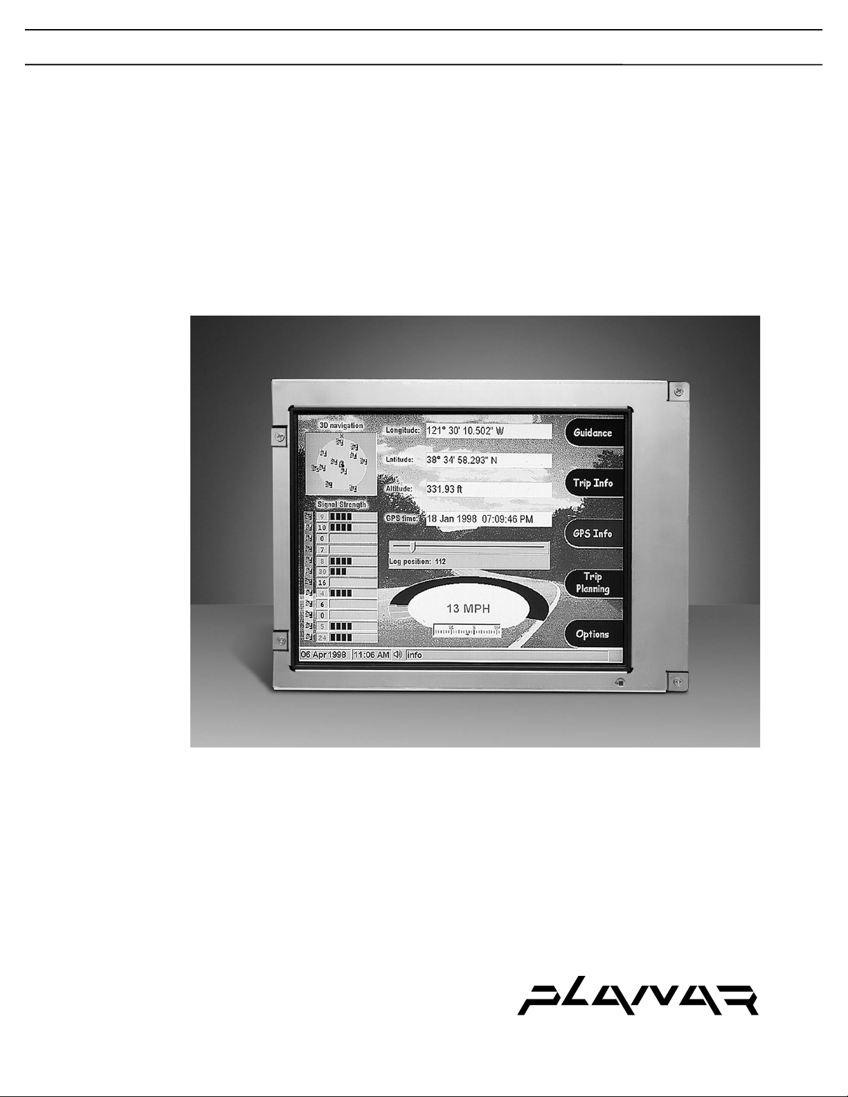
The LC640.480.33-AC is a 1000 nit 10.4" diagonal VGA color AMLCD flat panel
display module intended for commercial applications requiring outdoor viewability and
long life. Special attention to the total backlight design gives the display a wide, “singleBEF” viewing angle while maintaining luminance efficiency greater than 45 nit/W.
The display is convection cooled and does not require a fan, yet features a wide
operating temperature range. It is lightweight, compact, and rugged, and includes an
integrated inverter in a package approximately one inch thick. With fast cell response
and an 18-bit (6 bits per color) video interface, this display can show full motion video
images.
The LC640.480.33-AC is designed, tested, and characterized as an integrated system
made up of two subassemblies. The LCD subassembly includes a sealed optical cavity,
and the backlight/inverter subassembly includes a cold cathode fluorescent (CCFL)
backlight and inverter. Due to the sealed optical cavity, the backlight subassembly may
be replaced without exposing the back of the LCD cell and optical films to airborne
contaminants.
Features and Benefits
♦ 1000 nit typical luminance for sunlight-readability
♦ 3:1 contrast @ 100K Lux ambient for outdoor daylight use
♦ Wide +40/-60° vertical / ±70° horizontal viewing angle
♦ 100:1 digital dimming for efficient control over a wide range of ambient light
♦ 18-bit (6 bits per color) display interface for wide color range (262,144 colors)
♦ 30,000 hours MTBF for long service-free operating life
♦ Durable and lightweight enclosure for rugged conditions
♦ Convection cooling for operation without cooling fans
♦ 3H diffuse hard coated front surface for scratch protection
♦ Modular design for easy field replacement of backlight and inverter
♦ Automatic shutdown at low and high temperature extremes for product safety
LC640.480.33-AC Operations Manual (OM600-01) 3
Page 6
Installation and Handling
Do not drop, bend, or flex the display. Do not allow objects to strike the surface of the
display.
Mounting the Display
To maximize shock and vibration performance, the display must be properly mounted
using all four mounting hole locations. There are two recommended mounting
configurations as shown in Figure 1 using the hardware listed in Table 1 below.
Appropriate changes to these mounting configurations may be needed to meet specific
requirements or applications.
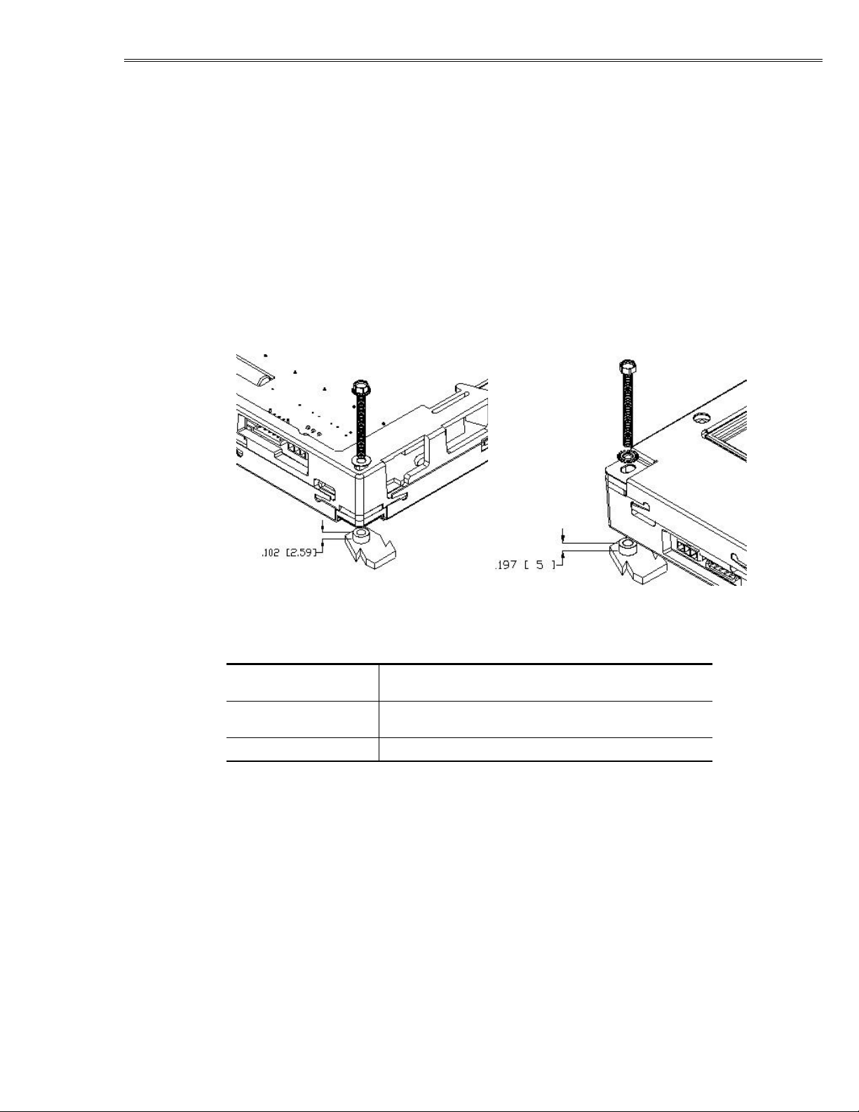
Figure 1. Mounting Options.
Display Face Down ECA Face Down
Table 1. Mounting Hardware.
Screw
Washer
Tightening torque
#6 SS, hex head or hex washer head, or M3 SS hex head
or hex washer head
Bearing washer for display face down bearing
application only Lockwasher, external type
4 oz-in \ 2.8x10⁵ dyne – cm
Mounting Display Face Down
Standoff spacers with a minimum height of 0.102" (2.59 mm) must be used at all four
mounting locations to prevent binding and deflection of the display. Threaded studs
anchored in a bezel would be a design variation of this mounting option.
Mounting ECA Face Down
When mounting the display with the mounting screws installed from the viewing side, it
is not necessary to incorporate a flat washer. Provide for proper vent clearance and an air
gap/isolation allowance of 0.197" (5 mm) or better as described below.
LC640.480.33-AC Operations Manual (OM600-01)4
Page 7

Vent Clearance
The LC640.480.33-AC display is a wide temperature display utilizing convection
cooling. It is imperative to allow ambient air unrestricted access to the cooling vents in
order to reliably operate the display at high temperatures
The vents for the lamp cavity are along the top and bottom edges of the display with the
openings facing the rear. The vents for the inverter cavity are along the top and bottom
faces of the display: four along the top surface and four along the bottom surface. Refer
to the mechanical outline drawing in Figure 15 for vent locations.
Isolation/Air Gap
The display generates high voltage AC to drive the CCFL tubes. High voltage is present
at numerous points on the backlight/inverter ECA which forms the rear surface of the
display, so your application should not place metal too near the ECA. In the interests of
both high voltage isolation and airflow for cooling, it is recommended that an air gap of
.197" (5 mm) or greater be maintained behind the display.
Ambient Light Sensor Clearance
Two backlight dimming modes utilize automatic brightness control (ABC). If the display
is to be operated in either of these modes, the ambient light sensor located on the front
bezel must be unobstructed. If the sensor is placed behind the same protective window as
the display active (viewing) area, the sensor operation may be affected due to light
scattering and reflections from display-generated light coupling to the sensor via the
window.
Cable Length
Due to the high frequencies present on the video interface, unterminated video cable
lengths of more than two feet (600 mm) are discouraged.
Cleaning
Care should be taken to minimize scratching. Clean the display front with a dry, soft
cloth such as a professional photographic lens cleaner. Disposable cleaning cloths are
recommended to minimize the risk of inadvertently scratching the display with particles
embedded in a re-used cloth. Particular care should be taken when cleaning displays with
polarizers or anti-glare and anti-reflective films. These films may delaminate if exposed
to certain chemicals.
Avoiding Image Retention
Image retention may occur when a fixed pattern is displayed for a long time. Use a
screen saver or image inversion to avoid image retention on the display.
LC640.480.33-AC Operations Manual (OM600-01) 5
Page 8

Specifications
Performance characteristics are guaranteed with the display at room temperature (25 °C)
and with the operating voltage within specifications, unless otherwise specified. Optical
performance is referenced to screen center at normal incidence and with the backlight at
maximum luminance unless otherwise specified.
Environmental Characteristics
Table 2. Environmental Characteristics.
Temperature
Operating
Operating survival
Storage
Humidity
Operating 95% RH @ 40 ºC, Non-condensing, per IEC 68-2-3
Altitude
Operating 10K ft per IEC 68-2-13
Non-operating 40K ft per IEC 68-2-13
Vibration (random)
Operating 0.02 g2/Hz, 5-500 Hz, 30 min. ea. axis, per IEC 68-2-34
Shock
Operating 100 g, 6 ms, half sine wave, 3 shocks per surface, per IEC 68-2-27
-10 to +70 °C
-20 to +80 °C
-25 to +85 °C
Mechanical Characteristics
Refer to mechanical outline drawing in Figure 15 on page 24.
Table 3. Mechanical Characteristics.
Display External Dimensions
width
height
depth
Weight (typical)
Display Active Area
width
height
Pixel Pitch
width
height
272.3 (10.72) nominal
199.9 (7.87) nominal
27.0 (1.06) nominal
900 g (31.7oz)
211.2 (8.31) nominal
158.4 (6.24) nominal
(millimeters (inches))
.33 (.0129) nominal
.33 (.0129) nominal
(millimeters (inches))
(millimeters (inches))
LC640.480.33-AC Operations Manual (OM600-01)6
Page 9

Optical Characteristics
Table 4. Optical Characteristics.
Luminance
Typical
Minimum
Contrast Ratio
Dark room ambient
500 Lux ambient
3K Lux ambient
100K Lux ambient
Color Coordinates
White field x = .339 typical
Luminance Non-uniformity
31% maximum With a white screen, max difference between any 2 of 5
Luminance Control (typical)
Dimming range 50:1 initial, 100:1 stabilized (Lmax after > 15 minutes
Ambient Light Sensor
Response
Field of view
Dynamic range
Viewing Angle
Horizontal
Vertical
(See Figure 10)
1000 NITs at screen center, initial
900 NITs at screen center, initial
200: 1 typical, 150:1 minimum
150:1 typical
50:1 typical
3:1 typical
y = .353 typical
points is defined as follows:
Lnu(%) = (1- (Lmin/Lmax)) x 100%
at max. lum., then Lmin at min. lum; dimming range =
Lmax/Lmin)
Visible light filtered ~420 to 675nm @ 50% pts.
±50 degrees typical to half sensitivity
0 to 3000 Lux typ.; assumes 18% scene reflectance
±70 degrees typ., White/black CR ≥ 5
+40/-60 degrees typ., White/black CR ≥ 5
Safety and EMI
The display will not inhibit the end product from compliance with UL1950, CSA22.2,
and IEC950.The display will not inhibit the end product from complying with FCC Part
15, Subpart J, Class B or EN55022 Class B when housed in a suitable enclosure.
Reliability and Backlight Life
The demonstrated system MTBF is to be greater than 30,000 hours with a 90%
confidence level at 25 °C. Refer to the following table for backlight life.
Table 5. Backlight Life.
Usage Backlight life (typical to 50% of initial luminance)
Continuous at full luminance 20K hours
Continuous at half luminance 100K hours
Typical use using ABC* 35K hours
* Automatic brightness control
LC640.480.33-AC Operations Manual (OM600-01) 7
Page 10

Interfacing and Operation
Control Basics
Power Requirements
The LC640.480.33-AC display requires two power supplies: +5 Vdc for the LCD logic
and +12 Vdc for the backlight. In Table 6 below, the backlight current and power are
referenced to maximum luminance, 25 °C ambient temperature.
Table 6. Input Power
Backlight
Backlight voltage V
Absolute max. voltage V
Steady state current (VH = +12 Vdc) I
Peak start-up current (VH = +12 Vdc) I
Power (VH = +12V) P
LCD
LCD voltage V
Absolute max. voltage V
VL permissible ripple (VL = +5V)
Current (VL = +5V) I
Power (VL = +5V) P
Symbol Min Typ Max Units
+10.8 +12.0 +13.2 Vdc
H
HMAX
H
HSU
H
L
LMAX
∆V
L
L
L
0 – +16 Vdc
– 1.9 2.5 Adc
– – 3.5 Adc
– 23 30 W
4.5 +5.0 +5.5 Vdc
0 – 6.0 Vdc
– – 100 mVpp
– 280 450 mAdc
– 1.4 2.3 W
CAUTION: Absolute maximum ratings are those values beyond which damage to
the device may occur.
Undervoltage Lockout (Backlight only)
An undervoltage lockout (UVLO) function is included which disables the backlight
under excessively low VH conditions. The UVLO circuit will disable the backlight at
approximately +8.5 Vdc as VH falls and will enable the backlight at approximately +9.5
Vdc as VH rises.
Power Sequencing (LCD only)
Certain restrictions on the behavior of the VL (+5 Vdc) source and in the application of
the VL source relative to the application or removal of the video signals must be
observed. These restrictions are shown in Figure 2, where “Vcc”= VL and “data” = video
signals.
LC640.480.33-AC Operations Manual (OM600-01)8
Page 11

Figure 2. Power Sequencing.
datat3t2
t1
Vcc
4.5V
4.5V
2.7V
where: t1 ≤ 10ms
0< t2 ≤ 10ms
0< t3 ≤ 1s
Applying video signals before VL is applied may cause a latchup condition. Allowing V
to remain “on” for a long period of time after video signals are removed—which stops
the cell scanning—may produce a latent image. In addition, there is a restriction
regarding dropouts on the VL supply as illustrated in Figure 3 (“Vcc”= VL). This is
related to the reset circuit for the LCD’s internal logic. If a dip in VL exceeds 10 ms in
duration or VL falls below 2.7 Vdc then the power sequencing procedure should be
followed.
Figure 3. VL Supply Dropouts.
Vcc
where: td ≤ 10ms
4.5V
2.7V
td
Backlight Signals
The dimming control and /DISABL inputs are analog, though the latter is intended to be
driven from either an open collector device or CMOS logic. The /ABCOFF input is a
CMOS-compatible digital input.
L
Table 7. Backlight Signal DC Characteristics.
Description Min Max Units Symbol
Absolute max. input voltage -0.3 +5.3 Vdc V
Dimming input voltage range 0 +5.0 Vdc V
IMAX
RLUM
Recommended pot. value 10 100 K ohm RLUM
RLUM HI source current – 600 µA I
/ABCOFF input +3.6
0
–
/DISABL input +4.5
0
–
+5.0
+1.4
0.5
+5.0
+1.0
1.3
Vdc
Vdc
mA
Vdc
Vdc
mA
RLUM
V
IHA
V
ILA
I
ILA
V
IHD
V
ILD
I
ILD
Note: Incorrect operation of the undervoltage lockout (UVLO) circuit may occur if
the /DISABL input is allowed to operate between V
ILD
and V
IHD
.
LC640.480.33-AC Operations Manual (OM600-01) 9
Page 12

Video Signals
Video Signal Characteristics
Video signal inputs on J3 are digital inputs and are compatible with CMOS logic.
Table 8. Video Signal DC Characteristics.
Description Symbol Minimum Maximum Units
Absolute Maximum Input Voltage V
Low-level Input Voltage V
High-level Input Voltage V
Low-level Input Current
High-level Input Current
1. I
2. I
Video Modes
The video interface automatically recognizes 480-, 400-, and 350-line formats. Mode
recognition depends on the polarity of the sync signals as shown in Table 9.
I
max
IL
1
2
applies to all signals except R/L and U/D. I
IL1
applies to all signals except ENAB, U/D, and R/L. I
IH1
I
I
I
I
IH
IL1
IL2
IH1
IH2
and R/L.
-0.3 VL + 0.3 Vdc
0 0.3V
0.7V
L
V
L
– 1 µA
– 60 µA
– 1 µA
– 60 µA
applies to signals R/L and U/D.
IL2
applies to signals ENAB, U/D,
IH2
L
Vdc
Vdc
Table 9. Video Modes.
Mode 480 line 400 line 350 line
Hsync (J3-3) negative negative positive
Vsync (J3-4) negative positive negative
In 400-line and 350-line modes, the screen image will be automatically centered as
shown in Figure 4 below.
Figure 4. Image centering.
data invalid period
data period
data invalid period
400 lines mode (TV=449)
40 lines
400 lines
40 lines
data invalid period
data period
data invalid period
350 lines mode (TV=449)
65 lines
350 lines
65 lines
LC640.480.33-AC Operations Manual (OM600-01)10
Page 13

Signal Timing
Video signal timing diagrams are shown in Figures 5, 6, and 7. The following table refers
to these diagrams.
Table 10. Video signal timing.
Parameter Symbol Mode Min Typ Max Units
Clock freq 1/Tc all – 25.18 28.33 MHz
hi time Tch all 5 – – ns
lo time Tcl all 10 – – ns
Data setup time Tds all 5 – – ns
hold time Tdh all 10 – – ns
Horiz. cycle TH all 30.0 31.78 –
sync all 750 800 900 clock
PW THp all 2 96 200 clock
Vertical cycle TV 480 515 525 560 line
sync 400 446 449 480 line
350 447 449 510 line
PW TVp all 1 – 34 line
Horiz.display time THd all 640 640 640 clock
Horiz. to clock THc all 10 – Tc-10 ns
Vsync to Hsync TVh all 0 – TH-THp clock
Enable setup time Tes – 5 – Tc-10 ns
hold time Tep – 2 640 640 clock
Hsync to Enable THe – 44 – TH-664 clock
µs
Table 11 below summarizes timing for the different vertical modes given typical vertical
sync “cycle” (TV) values. In this table, data for line TVn is displayed as the first top row
on the screen.
Table 11. Vertical mode video signal timing.
Mode Symbol 480 line 400 line 350 line
V-data start TVs 34 34 61
V-data period TVd 480 400 350
V-display start TVn 34 443-TV 445-TV
V-display period – 480 480 480
The LC640.480.33-AC display timing is fundamentally the same as the Sharp
LQ10D421 display. Horizontal display position is determined by the rising edge of the
ENAB signal, and the ENAB signal has no relation to the vertical display position. If
ENAB is permanently low, display starts from the data at “C104” referred to in the
timing diagrams in Figures 5, 6, and 7. ENAB should not be left at a logic high
permanently. In 400 and 350 line modes, data should be at a logic low during the vertical
invalid period.
LC640.480.33-AC Operations Manual (OM600-01) 11
Page 14

Figure 5. Timing Diagram, 480-line mode.
0.3Vcc
Number of V-data line
Vertical invalid data period
0.3Vcc
0.7Vcc
Vertical invalid data period
Horizontal invalid data period
Horizontal invalid data period
TH
* Only when enable terminal is fixed "low"
0.3Vcc
TV
Number of H-data
D640
D639
0.3Vcc
0.7Vcc
0.3Vcc
Tcl
Tc
Tch
0.7Vcc
D3
Tds Tdh
D2D1
0.3Vcc
34
THd
Tcp
0.7Vcc
Tcs
DH479 DH480DH3DH2DH1
TVd
Number of line
TVs
Number of clock
C2* C104*
C1*
THc
0.7Vcc
THp
0.3Vcc
0.3Vcc
0.3Vcc 0.3Vcc 0.3Vcc 0.3Vcc
THc
TVp
2
1
TVh
LC640.480.33-AC Operations Manual (OM600-01)12
Page 15

Figure 6. Timing Diagram, 400-line mode.
0.7Vcc
Number of V-data line
Vertical invalid data period
0.7Vcc
0.7Vcc
Vertical invalid data period
Horizontal invalid data period
Horizontal invalid data period
TH
* Only when enable terminal is fixed "low"
0.3Vcc
TV
Number of H-data
D640
D639
0.3Vcc
0.7Vcc
0.3Vcc
Tcl
Tc
Tch
0.7Vcc
D3
Tds Tdh
D2D1
0.3Vcc
34
THd
Tcp
0.3Vcc
Tcs
DH399 DH400DH3DH2DH1
TVd
Number of line
TVs
Number of clock
C2* C104*
C1*
THc
0.7Vcc
0.3Vcc 0.3Vcc 0.3Vcc 0.3Vcc
THp
0.3Vcc
0.3Vcc
THc
TVp
2
1
TVh
LC640.480.33-AC Operations Manual (OM600-01) 13
Page 16

Figure 7. Timing Diagram, 350-line mode.
0.3Vcc
Number of V-data line
Vertical invalid data period
0.3Vcc
0.7Vcc
Vertical invalid data period
Horizontal invalid data period
Horizontal invalid data period
TH
* Only when enable terminal is fixed "low"
0.7Vcc
DH349 DH350DH3DH2DH1
TV
TVd
Number of H-data
D640
D639
0.3Vcc
0.7Vcc
0.3Vcc
Tcl
Tc
Tch
0.7Vcc
0.3Vcc
THc
0.3Vcc 0.3Vcc 0.3Vcc 0.3Vcc
THp
0.7Vcc
0.7Vcc
D3
Tds Tdh
D2D1
Number of clock
C2* C104*
C1*
0.3Vcc
Number of line
61
Tcs
Tcp
0.7Vcc
TVs
TVp
TVh
2
1
THd
THc
LC640.480.33-AC Operations Manual (OM600-01)14
Page 17

Video Characteristics
Colors are developed in combination with 6-bit signals (64 steps in grayscale) of each
primary red, green, and blue color. This process can result in up to 262,144 (64x64x64)
colors. The mapping of the eighteen video data inputs is shown in Table 12.
Table 12. Video Data Color/Grayscale Map
Display colors
Basic
colors
Red
grayscale
Green
grayscale
Black
Blue
Red
Magenta
Green
Cyan
Yellow
White
Black
dark
↑
↓
bright
Red
Black
dark
↑
↓
bright
Green
Data signal (0: Low level, 1: High level)
R5 R4 R3 R2 R1 R0 G5 G4 G3 G2 G1 G0 B5 B4 B3 B2 B1 B0
0 0 0 0 0 0
0 0 0 0 0 0
1 1 1 1 1 1
1 1 1 1 1 1
0 0 0 0 0 0
0 0 0 0 0 0
1 1 1 1 1 1
1 1 1 1 1 1
0 0 0 0 0 0
0 0 0 0 0 1
0 0 0 0 1 0
↑
↓
1 1 1 1 0 1
1 1 1 1 1 0
1 1 1 1 1 1
0 0 0 0 0 0
0 0 0 0 0 0
0 0 0 0 0 0
↑
↓
0 0 0 0 0 0
0 0 0 0 0 0
0 0 0 0 0 0
0 0 0 0 0 0
0 0 0 0 0 0
0 0 0 0 0 0
0 0 0 0 0 0
1 1 1 1 1 1
1 1 1 1 1 1
1 1 1 1 1 1
1 1 1 1 1 1
0 0 0 0 0 0
0 0 0 0 0 0
0 0 0 0 0 0
↑
↓
0 0 0 0 0 0
0 0 0 0 0 0
0 0 0 0 0 0
0 0 0 0 0 0
0 0 0 0 0 1
0 0 0 0 1 0
↑
↓
1 1 1 1 0 1
1 1 1 1 1 0
1 1 1 1 1 1
0 0 0 0 0 0
1 1 1 1 1 1
0 0 0 0 0 0
1 1 1 1 1 1
0 0 0 0 0 0
1 1 1 1 1 1
0 0 0 0 0 0
1 1 1 1 1 1
0 0 0 0 0 0
0 0 0 0 0 0
0 0 0 0 0 0
↑
↓
0 0 0 0 0 0
0 0 0 0 0 0
0 0 0 0 0 0
0 0 0 0 0 0
0 0 0 0 0 0
0 0 0 0 0 0
↑
↓
0 0 0 0 0 0
0 0 0 0 0 0
0 0 0 0 0 0
Blue
grayscale
Black
dark
↑
↓
bright
Blue
0 0 0 0 0 0
0 0 0 0 0 0
0 0 0 0 0 0
↑
↓
0 0 0 0 0 0
0 0 0 0 0 0
0 0 0 0 0 0
LC640.480.33-AC Operations Manual (OM600-01) 15
0 0 0 0 0 0
0 0 0 0 0 0
0 0 0 0 0 0
↑
↓
0 0 0 0 0 0
0 0 0 0 0 0
0 0 0 0 0 0
0 0 0 0 0 0
0 0 0 0 0 1
0 0 0 0 1 0
↑
↓
1 1 1 1 0 1
1 1 1 1 1 0
1 1 1 1 1 1
Page 18

Pixel Position
The position of pixel data, relative to the color filter orientation and scan direction
inputs is shown in Figure 8. Refer to the timing diagrams in Figures 5, 6, and 7 for
horizontal pixel position (D1 through D640), and for vertical line position (DH1
through DH480).
Figure 8. Pixel position of input data (480-line mode).
UP
D1,DH1 D2,DH1 D3,DH1
D1,DH2 D2,DH2
D1,DH3
R G B
D640,DH1
Connectors
D1,DH480
D640,DH480
R/L=H
U/D=L
The display image may be rotated 180 degrees using the R/L and U/D signals present
on J3. Refer to Inverting the Display on page 21 for more information.
The LC640.480.33-AC display has three connectors on the side of the display. J3 is the
video connector, J2 is the dimming connector, and J1 is the backlight power connector.
Figure 9. Connector Locations.
J3
J2
J1
LC640.480.33-AC Operations Manual (OM600-01)16
Page 19

Video Connector (J3)
Pin
Signal
Description
Pin
Signal
Description
Video signals and LCD display power (VL) are applied via a polarized 34-pin dual-row 2
mm pitch header with gold plated (30µ") contact surfaces and ejector/latching ears. The
connector is equivalent to a Samtec EHT-117-01-S-D-RA and the recommended mating
cable is a Samtec TCSD-117. Consult your Samtec representative (1-800-SAMTEC9) for
cable and connector options. Note that J3 is electrically and mechanically independent of
the backlight assembly.
Table 13. Video Connector (J3) Pinouts.
1 GND Ground 2 CK Dot Clock
3 HSync Horiz. Sync 4 VSync Vert. Sync
5 GND Ground 6 R0 Red data (LSB)
7 R1 Red data 8 R2 Red data
9 R3 Red data 10 R4 Red data
11 R5 Red data (MSB) 12 GND Ground
13 G0 Green data (LSB) 14 G1 Green data
15 G2 Green data 16 G3 Green data
17 G4 Green data 18 G5 Green data (MSB)
19 GND Ground 20 B0 Blue data (LSB)
21 B1 Blue data 22 B2 Blue data
23 B3 Blue data 24 B4 Blue data
25 B5 Blue data (MSB) 26 GND Ground
27 ENAB
29 V
L
31 R/L
1
LCD Power 30 GND Ground
2
Horiz. Scan
Enable
1
28 V
2
32 U/D
L
3
LCD Power
Vert. Scan
33 GND Ground 34 GND Ground
Ground (GND) is isolated from the display metal bezel.
1
Do not keep ENAB at a static high level.
2
Default is logic high or open connection. Reverse scan direction is logic low.
3
Default is logic low or open connection. Reverse scan direction is logic high.
3
LC640.480.33-AC Operations Manual (OM600-01) 17
Page 20

Dimming Connector (J2)
A dimming voltage or potentiometer, plus optional backlight mode and disable logic
inputs are applied via J2, which is a polarized 5-pin inline, 2.5 mm pitch header, tin
plated with a friction lock. The connector is equivalent to the Molex 5268-NA ‘SPOX’
series, part number 22-05-7055. The recommended mating connector is a Molex 5264-N
series housing, part number 50-37-5053 and Molex 5263 series crimp pin, part number
08-70-1040. The recommended wire size is 22-28 AWG stranded. Refer to on page 19
for more information.
Table 14. Dimming Connector (J2) Pinouts.
Pin Symbol Function
1 RLUM HI Pot high side voltage source output
2 VRLUM Analog dimming input
3 GND Signal ground (return)
4 /ABCOFF Automatic brightness control mode
disable input
5 /DISABL Backlight disable input
Backlight Power Connector (J1)
Backlight power (VH) is applied via J1, which is a polarized 3 pin, 3mm pitch header
with gold plated (15µ") contact surfaces and a release latch. J1 is equivalent to a Molex
43650-0301 (“Micro-Fit 3.0” series). The recommended mating connector is a Molex
part number 43645-0300 (housing) and Molex part number 43030-0008 (crimp pin). The
recommended wire size is 20 AWG stranded.
Table 15. Backlight Power Connector (J1) Pinouts.
Pin Symbol Function
1 GND Power ground
2 V
3 GND Power ground
Note: Power Ground (GND) is isolated from the display metal bezel. All signals
and power on the backlight are also isolated from the J3-related AMLCD display
circuits.
H
Backlight power
LC640.480.33-AC Operations Manual (OM600-01)18
Page 21

Optical Features
-V
-H
θ
+V
+H
Viewing Angle
Viewing angles are defined per Figure 10 below:
Figure 10. Viewing Angles.
Normal Line
6 o’clock direction
Response Times
The rise response time (from white to black) is 25 ms typical and the fall response time
(from black to white) is 45 ms typical. This is shown in Figure 11.
Figure 11. Response Times.
Photo-
detector
output
(Relative Value)
100%
90%
where:
+Horizontal angle(+70)
+H
θ
-Horizontal angle (-70)
-H
θ
+Vertical angle (+40)
+V
θ
-Vertical angle (-60)
-V
θ
and R/L and U/D = default
blackwhite
white
r = Rise (wht to blk): 25 ms typ
τ
f = Fall (blk to wht): 45 ms typ
τ
10%
0%
r
τ
f
τ
time
Dimming
Initial backlight dimming is performed by decreasing tube current, allowing for
substantially higher tube life in applications that do not require maximum luminance.
The user can adjust the display for the optimum combination of luminance, life, and
power consumption for the target application.
LC640.480.33-AC Operations Manual (OM600-01) 19
Page 22

Backlight Dimming Modes
The backlight may be operated in one of four modes without the use of jumpers or
switches. The mode is selected based on the state of the /ABCOFF input and on whether
the dimming input is left open or connected to a voltage source.
Table 16. Backlight Dimming Modes.
Mode VRLUM /ABCOFF Comments
Extended
backlight life
Manual dimming Rpot or
Automatic
brightness
control (ABC)
Biased ABC Rpot or
open GND Display operates at approximately half
luminance.
GND Minimum-to-maximum luminance as defined
Vin
open open Default mode. Minimum-to-maximum
open Combination of dimming control and
Vin
by pot or voltage at V
0 Vdc = min, +5 Vdc = max luminance
luminance as defined by ambient light sensor:
0 lx = min, 3000 lx = max luminance.
ambient light sensor sets display luminance.
In this mode, V
compared to the ambient light sensor, hence
V
can drive luminance to either extreme
RLUM
regardless of ambient light conditions.
Ambient light influence max is capped at
3000 lux.
RLUM
(J2-2):
RLUM
has twice the influence
Dimming Control Interfacing
An analog dimming control is available on J2. Some common methods to use this input
are shown in Figure 12. In this figure, the schematic shown is an approximation of the
circuitry actually present in the LC640.480.33-AC and is meant to give an indication of
the dimming interface DC characteristics. The V
which may be supplied either directly or generated from a potentiometer.
In Figure 12 below, A, B, and C are analog dimming methods. D, E, and F are methods
to drive the two mode set inputs.
Figure 12. Dimming Control Methods.
input expects a 0 to +5 Vdc voltage
RLUM
LC640.480.33-AC Operations Manual (OM600-01)20
Page 23

Method A represents sourcing the dimming input from a voltage source such as a DAC or
analog op amp. The device should be powered from +5 Vdc such that the device’s output
will not exceed the allowable input range of the dimming input.
Method B creates the dimming voltage from a potentiometer. The recommended value
for the pot is from 10K to 100K ohms. If J2 pin 1 is used as the pot high-side voltage
reference as shown, then a lower pot value may restrict the maximum luminance
attainable from the backlight as the drop due to the series limiting resistor becomes
significant. Pot values greater than 100K ohm will result in response non-linearity due to
loading from the dimming input. Some gain is provided in the dimming input path of the
backlight to compensate for interface losses whereby the input dimming range provided
by the source does not quite reach the 0 or +5 Vdc rails.
Method C shows a simple strap which sets the display to maximum luminance. If the
input is left unconnected, the input will be in the mid-level (half luminance) condition.
Method D represents a CMOS or TTL logic gate, or a comparator to drive the backlight
/DISABL input.
Method E shows an open collector device such as a bipolar transistor or FET.
Method F represents a switch or jumper.
In all cases, the return is to J2 pin 3. By its nature, the automatic brightness control
disable input (/ABCOFF) would be most likely be either permanently open or
permanently strapped to ground.
Inverting the Display
If the display needs to be physically inverted due to mechanical packaging or optical
(e.g. vertical viewing angle) considerations, the display image can be rotated 180
degrees. This is described in Table 17.
Table 17. Inverting the Display.
Signal: R/L U/D Image rightside up when:
Default orientation 1 0 J3 at left, ambient light sensor at top.
Reverse orientation 0 1 J3 at right, ambient light sensor at bottom.
LC640.480.33-AC Operations Manual (OM600-01) 21
Page 24

Temperature Considerations
Luminance, %
Backlight Power, W
Thermal Shutdown
A thermal sensor referenced to the center of the backlight/inverter ECA prevents the
inverter from starting at an ambient temperature of –30 °C or below, and will shut off the
backlight at an ambient temperature of approximately +90 °C and above.
Luminance Variation Due to Ambient Temperature
Although the inverter features regulated lamp current drive, luminance will vary across
the temperature range due to the characteristics of the CCFL tubes. Lamp luminance
decreases at low temperatures as the mercury condenses out of the gas and it decreases
again at high temperatures as the tube phosphors become less efficient. The
LC640.480.33-AC has been designed to provide peak luminance at normal room
temperatures.
Backlight power consumption decreases as temperatures climb as the working voltage of
the CCFL tubes decreases. The graph in Figure 13 indicates typical performance across
temperature.
Figure 13. Luminance vs. Temperature.
Luminance vs. Temperature
100
90
80
70
60
50
40
30
20
10
0
-20 -10 0 10 20 30 40 50 60 70 80
ta, C
30.0
25.0
20.0
15.0
10.0
5.0
0.0
Lum, %
PH, W
LC640.480.33-AC Operations Manual (OM600-01)22
Page 25

Warm-up Characteristic
Center Luminance, %
Backlight Pwr, W
Some time after startup is required to allow the CCFL tubes to reach their normal
operating temperature. The graph in Figure 14 shows the typical room temperature
warmup curve for the LC640.480.33-AC when set to maximum luminance. As can be
seen, luminance is at nearly 95% of the final value after five minutes of operation, and
99% of the final value at 10 minutes after startup.
Figure 14. Warmup Curve.
Warmup Curve
100
80
60
40
20
0
0 2 4 6 8 10 12 14 16 18 20 22 24 26 28 30 32 34
Display Dimensions
Time, minutes
23.0
22.5
22.0
21.5
21.0
20.5
20.0
Lum, %
PH
The recommended clearance shown in Figure 15 illustrates the distance behind the
display ECA which should be left for free low of air for the purposes of convection
cooling. In Figure 15, dimensions are in millimeters. Tolerances unless specified are as
follows:
.x ±0.50
.xx ±0.25
Note: The dimensions in this drawing are approximate. Please contact Planar
Applications Engineering to request the actual drawing prior to beginning your
design.
LC640.480.33-AC Operations Manual (OM600-01) 23
Page 26

Figure 15. Display Dimensions.
LC640.480.33-AC Operations Manual (OM600-01)24
Page 27

Description of Warranty
This description is not the full warranty, and should not be construed as a substitute for the full
warranty. A copy of the full warranty is available upon request.
Planar warrants that the goods it sells will be free of defects in materials and workmanship, and that
these goods will substantially conform to the specifications furnished by Planar, and to any drawings or
specifications furnished to the Seller by the Buyer if approved by the Seller. This warranty is effective
only if Planar receives notice of such defect or non-conformance during the period of warranty, which
begins the day of delivery.
The goods Planar sells are warranted for a period of one year unless otherwise agreed to by Planar and
the Buyer. The Buyer must return the defective or non-conforming goods, upon request, to Planar not
later than 30 days after Planar’s receipt of notice of the alleged defect or non-compliance. Buyer shall
prepay transportation charges, and Planar shall pay for return of the goods to the Buyer. No goods are
to be returned to Planar without prior permission.
The warranty does not apply in cases of improper or inadequate maintenance by the Buyer,
unauthorized modification of the goods, operation of the goods outside their environmental
specifications, neglect or abuse of the goods, or modification or integration with other goods not
covered by a Planar warranty when such modification or integration increases the likelihood of damage
of the goods.
Ordering Information
Product Part Number
LC640.480.33-AC 996-0403-00
Design and specifications are subject to change without notice.
Planar Systems continues to provide optional, and in many cases custom, features to address the
specific customer requirements. Consult Planar Sales for pricing, lead time and minimum quantity
requirements.
Support and Service
Planar is a U.S. company based in Beaverton, Oregon and Espoo, Finland, with a world-wide sales
distribution network. Full application engineering support and service are available to make the
integration of Planar displays as simple and quick as possible for our customers.
RMA Procedure: For a Returned Material Authorization number, please contact
Planar Systems, Inc. with the model number(s) and serial number(s). When returning goods for repair,
please include a brief description of the problem, and mark the outside of the shipping container with
the RMA number.
Page 28

North & South America OEM Sales Europe & Asia-Pacific OEM Sales
Planar Systems, Inc.
1400 NW Compton Drive
Beaverton, OR 97006-1992
Tel. +1 (503) 690 1100
Fax +1 (503) 690 1493
sales@planar.com
app_eng@planar.com
Planar Systems, Inc.
Olarinluoma 9, P.O. Box 46
FIN-02201 Espoo, Finland
Tel. +358 9 42 0010
Fax +358 9 420 0200
intlsales@planar.com
tech_support@planar.com
Visit the Planar web site: http://www.planar.com
OM600-01
 Loading...