


LC1502R
USER’S MANUAL
www.planar.com

2
Table of Contents
UUssaaggee NNoottiiccee
Safety and Use Precautions . . . . . . . . . . . . . . . . . . . . . . . . . . . . . . . . . . . . . . . . . 3
IInnttrroodduuccttiioonn
About the LC1502R . . . . . . . . . . . . . . . . . . . . . . . . . . . . . . . . . . . . . . . . . . . . . . . . . 4
Package Overview . . . . . . . . . . . . . . . . . . . . . . . . . . . . . . . . . . . . . . . . . . . . . . . . . . 5
IInnssttaallllaattiioonn
Product Overview . . . . . . . . . . . . . . . . . . . . . . . . . . . . . . . . . . . . . . . . . . . . . . . . . . 6
Connector Descriptions . . . . . . . . . . . . . . . . . . . . . . . . . . . . . . . . . . . . . . . . . . . . 7
Mounting . . . . . . . . . . . . . . . . . . . . . . . . . . . . . . . . . . . . . . . . . . . . . . . . . . . . . . . . . . 8
Start Your Installation . . . . . . . . . . . . . . . . . . . . . . . . . . . . . . . . . . . . . . . . . . . . . . . 9
UUsseerr CCoonnttrroollss
Control Buttons . . . . . . . . . . . . . . . . . . . . . . . . . . . . . . . . . . . . . . . . . . . . . . . . . . . 10
How to Use the OSD Menus . . . . . . . . . . . . . . . . . . . . . . . . . . . . . . . . . . . . . . . 11
On-Screen Display Menus
. . . . . . . . . . . . . . . . . . . . . . . . . . . . . . . . . . . . . . 11
BBrriigghhttnneessss CCoonnttrrooll
Automatic Brightness Control . . . . . . . . . . . . . . . . . . . . . . . . . . . . . . . . . . . . . 13
Manual Brightness Control . . . . . . . . . . . . . . . . . . . . . . . . . . . . . . . . . . . . . . . . 14
Minimum Brightness Limit . . . . . . . . . . . . . . . . . . . . . . . . . . . . . . . . . . . . . . . . 15
Maximum Brightness Mode . . . . . . . . . . . . . . . . . . . . . . . . . . . . . . . . . . . . . . . 16
SSppeecciiffiiccaattiioonnss
Electrical and Optical . . . . . . . . . . . . . . . . . . . . . . . . . . . . . . . . . . . . . . . . . . . . . . 17
Mechanical and Environmental . . . . . . . . . . . . . . . . . . . . . . . . . . . . . . . . . . . . 18
Compatible Video Modes . . . . . . . . . . . . . . . . . . . . . . . . . . . . . . . . . . . . . . . . . . 18
Reliability and Life . . . . . . . . . . . . . . . . . . . . . . . . . . . . . . . . . . . . . . . . . . . . . . . . . 19
Safety and Regulatory Certifications . . . . . . . . . . . . . . . . . . . . . . . . . . . . . . . 19
AAvvaaiillaabbllee OOppttiioonnss
Power Supply and AC Power Cord . . . . . . . . . . . . . . . . . . . . . . . . . . . . . . . . . 20
Cooling Kit . . . . . . . . . . . . . . . . . . . . . . . . . . . . . . . . . . . . . . . . . . . . . . . . . . . . . . . . 21
Touch Screens . . . . . . . . . . . . . . . . . . . . . . . . . . . . . . . . . . . . . . . . . . . . . . . . . . . . 22
NFI Touch Screen
. . . . . . . . . . . . . . . . . . . . . . . . . . . . . . . . . . . . . . . . . . . . . . .22
Capacitive Touch Screen
. . . . . . . . . . . . . . . . . . . . . . . . . . . . . . . . . . . . . . . .24
AAppppeennddiixx
Troubleshooting . . . . . . . . . . . . . . . . . . . . . . . . . . . . . . . . . . . . . . . . . . . . . . . . . . 25
Warning Signal . . . . . . . . . . . . . . . . . . . . . . . . . . . . . . . . . . . . . . . . . . . . . . . . . . . . 25
Mechanical Outline . . . . . . . . . . . . . . . . . . . . . . . . . . . . . . . . . . . . . . . . . . . . . . . 26
Warranty . . . . . . . . . . . . . . . . . . . . . . . . . . . . . . . . . . . . . . . . . . . . . . . . . . . . . . . . . . 27
Support and Service . . . . . . . . . . . . . . . . . . . . . . . . . . . . . . . . . . . . . . . . . . . . . . .27

3
Usage Notice
WWaarrnniinngg
- To prevent the risk of fire or shock hazards, do not directly expose this product to
rain or moisture.
WWaarrnniinngg
- Please do not open or disassemble the product as this may cause electric shock.
SSaaffeettyy aanndd UUssee PPrreeccaauuttiioonnss
Follow all warnings, precautions and maintenance as recommended in this User's Manual to
maximize the life of your monitor.
• Turn off the product before cleaning.
• Use only a dry soft cloth or clean room wiper when cleaning the LCD panel surface.
• Use a soft cloth moistened with mild detergent to clean the monitor housing.
• Use only a high-quality and safety-approved 12V power supply.
• Do not touch the LCD panel surface with sharp or hard objects.
• Do not use abrasive cleaners, waxes or solvents for cleaning.

4
Introduction
AAbboouutt tthhee LLCC11550022RR
The LC1502R is a high performance monitor designed for demanding applications. The monitor
consists of a 15" diagonal flat panel liquid crystal display (LCD) housed in a metal enclosure with an
integrated ambient light sensor to facilitate automatic brightness control.
FFeeaattuurreess iinncclluuddee::
• Very high bright 1000 cd/m
2
brightness for sunlight readability
• Automatic brightness control to auto adjust the brightness to ambient conditions
• Manual brightness control mode to allow the user to control the brightness
• Wide 0 - 50°C operating temperature range
• Long backlight life: >40000 hours operating time before reaching half brightness
• Rugged vibration and shock characteristics
• Conformance to FCC/EN55022 Class B for low EMI
• 1024 x 768 XGA resolution
• Auto-adjustment function for jitter-free operation
• Optional cooling kit to reduce solar loading
• Optional 12V AC/DC power supply
• Optional capacitive and NFI touch screens

5
PPaacckkaaggee OOvveerrvviieeww
VGA Signal Cable
Quick Start Guide
6
Installation
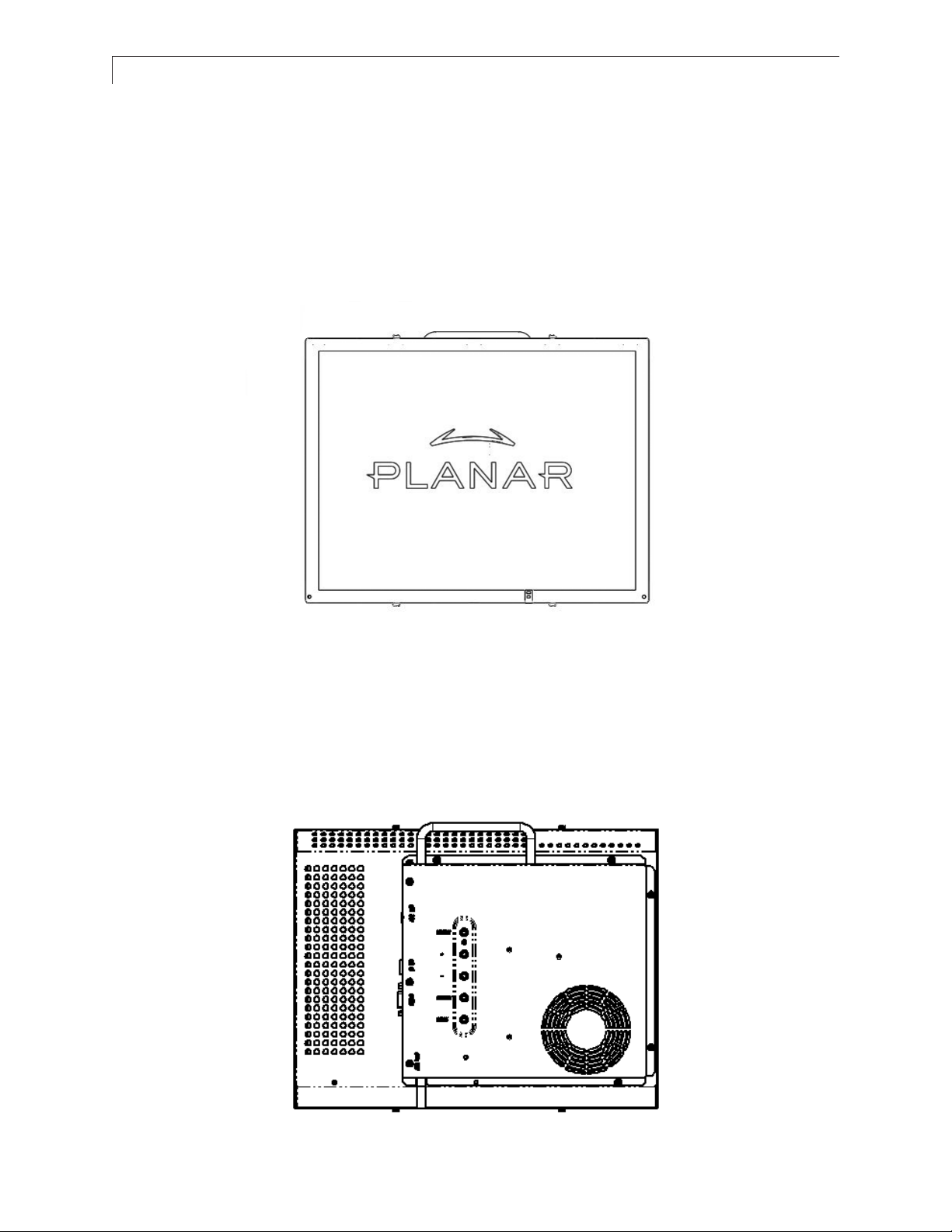
PPrroodduucctt OOvveerrvviieeww
•
FFrroonntt VViieeww
•
RReeaarr VViieeww
7
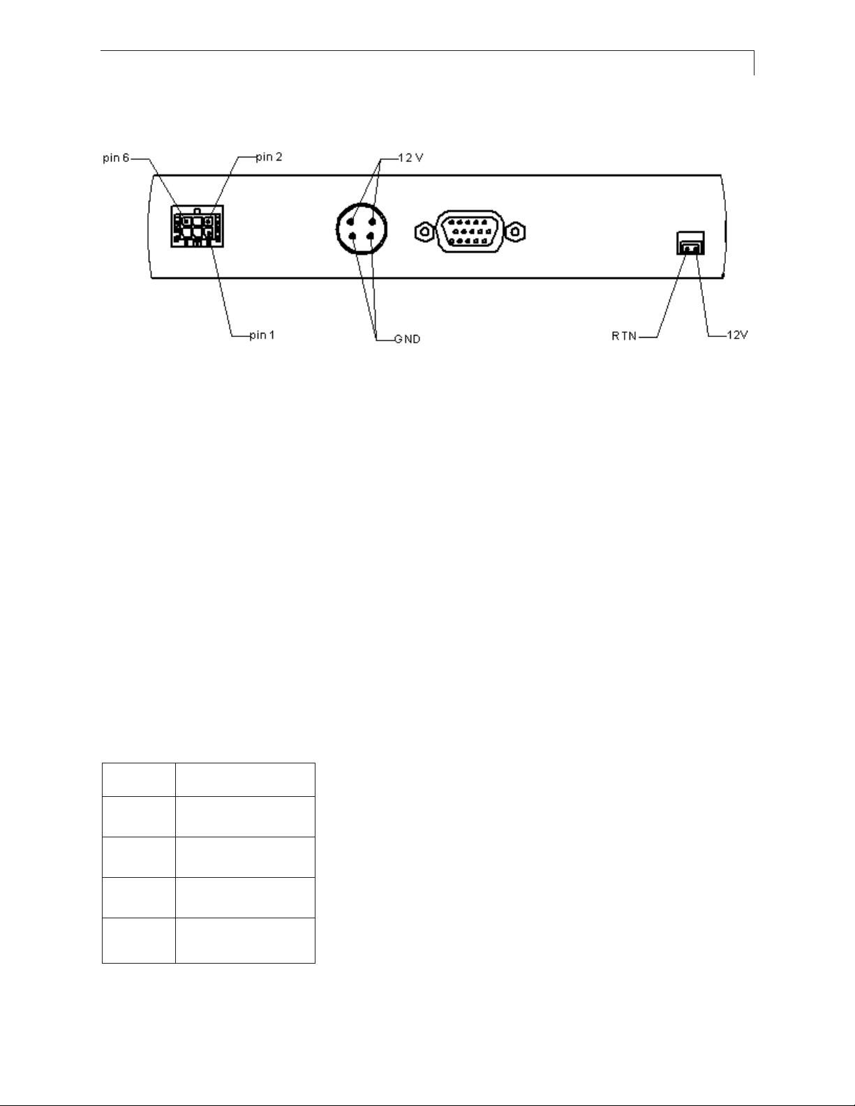
CCoonnnneeccttoorr VViieeww
CCoonnnneeccttoorr DDeessccrriippttiioonnss
11.. VViiddeeoo IInntteerrffaaccee CCoonnnneeccttoorr
Standard D-sub Analog; 15-pin D-sub connector
22.. PPoowweerr IInnppuutt CCoonnnneeccttoorr
Connector type: 4-pin mini DIN socket
Manufacturer: Singatron Enterprise Co. (Taiwan)
Part Number: 2MJ-0402A120
Mating Connector: 2MP-0402 series
Power Connector Pin Configuration
Pin Description
1 +12V DC
2 +12V DC
3 Ground
4 Ground
8
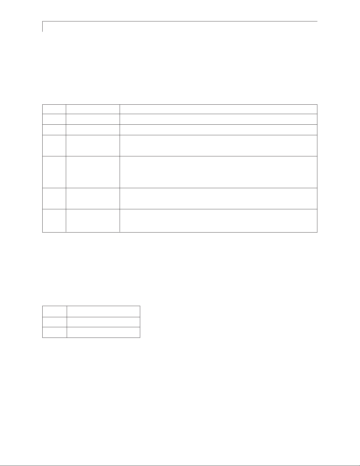
33.. EExxtteerrnnaall DDiimmmmiinngg CCoonnnneeccttoorr
Connector type: Molex Micro Fit 3.0
Mating connector: Molex 43025-0600 (housing) and Molex
43030 (terminals)
EExxtteerrnnaall DDiimmmmiinngg CCoonnnneeccttoorr PPiinn CCoonnffiigguurraattiioonn aanndd DDeessccrriippttiioonn
Pin Name Description
1 Ground Electrical ground
2 Reserved For factory use only, leave unconnected
3 DIM_Input 0-5V analog input for external dimming, connect to wiper of
dimming pot if used
4 /Ext_DIM, Input to determine brightness control mode; has 10k pull up to +5V
Logic high (or unconnected) = Automatic Brightness Control mode
Logic low = Manual Brightness Control mode
5 Ground Electrical ground; connect to lower leg of dimming potentiometer
if used
6 Vref +5V reference voltage output with 470 ohm series resistance;
connect to upper leg of dimming potentiometer if used
44.. CCoooolliinngg KKiitt PPoowweerr OOuuttppuutt CCoonnnneeccttoorr
Note: There is no need to connect to this connector. Information is shown for reference only. If a
Cooling Kit option is ordered, the required cooling kit power cable will be installed at the factory.
OOppttiioonnaall CCoooolliinngg KKiitt PPiinn CCoonnffiigguurraattiioonn
Pin Description
1 Switched Return
2 +12V output
MMoouunnttiinngg
M4 threaded holes are provided in the sides of the monitor housing for mounting purposes. The
blind holes will accommodate 10 mm long screws. See the mechanical outline drawing 076-0579-00
at www.planar.com/support for details.
9
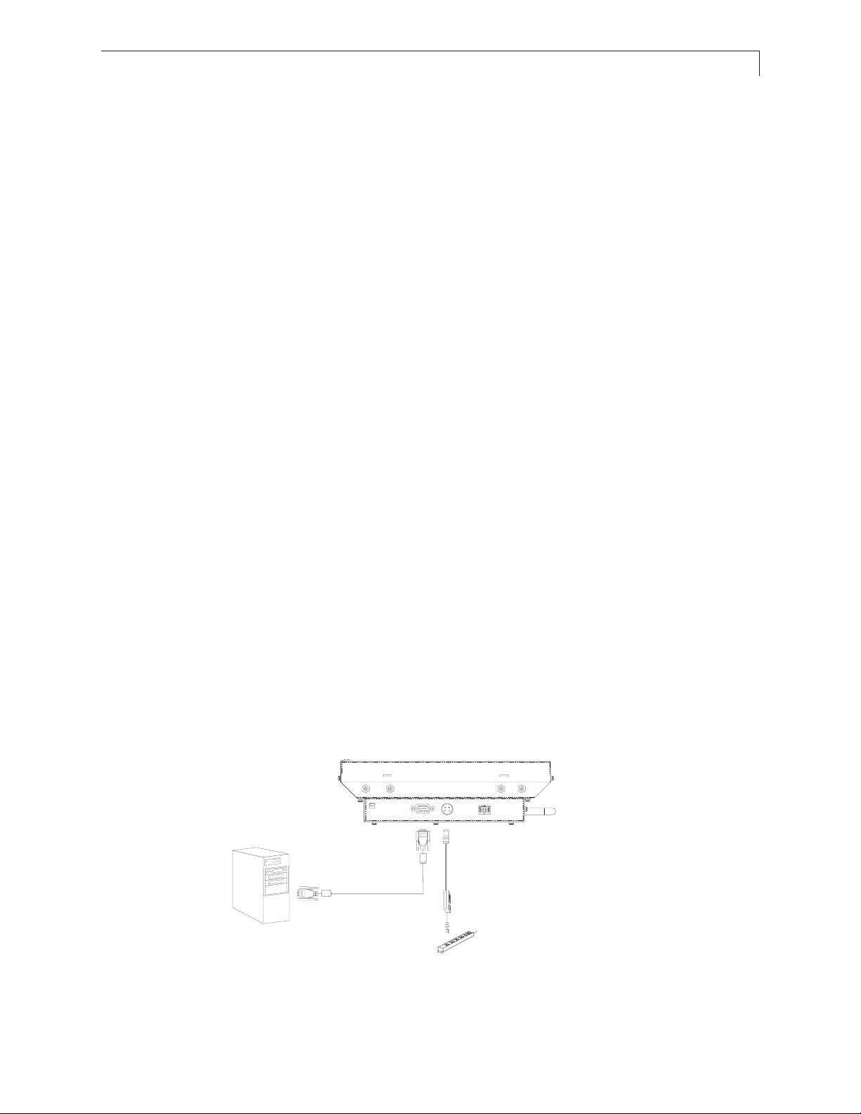
SSttaarrtt YYoouurr IInnssttaallllaattiioonn
CCoonnnneeccttiinngg tthhee DDiissppllaayy ((FFiigguurree 11..00))
To configure the monitor, please refer to the following figure and procedures.
1. Be sure the computer or video source is turned off.
2. Connect the 12V DC power(1.0). During initial turn on with no video applied, the display will
automatically power on with a self test pattern displayed. The self test pattern consists of
alternating screens of black, white, red, green, and blue.
3. Connect the VGA signal cable from display VGA input connector to the 15-pin connector of your
host computer and tighten the screws(1.0).
4. If needed, connect to the external dimming connector(1.0). See details in the Brightness Control
section of this document.
5. Turn on your computer or video source.
NNoottee::
Once video is applied, self test mode is automatically cancelled and will no longer function
when video is removed.
NNoottiiccee::
To ensure the LCD display will work well with your system, please configure the display mode
of your graphic card for a 1024 x 768 resolution and a 75 Hz refresh rate.
Figure 1.0
USB or Serial Cable
(Touch Versions)
Optional US or EU
Power Supply Kit
(For ordering information,
contact your sales
representative)
VGA Cable

10
User Controls
CCoonnttrrooll BBuuttttoonnss
Displays the OSD menus
1. Decreases the value of the adjustment
items.
2. Decreases the minimum brightness
limit of the display image.
1. Increases the value of the adjustment
items.
2. Increases the minimum brightness limit
of the display image.
No./ Icon Control Function
Menu button Display the OSD menus
Select/Auto Select- To select the adjustment items
Brightness Minus/ 1.Decreases the brightness of
Minus the display image.
Brightness Plu s/ 1.Increases the brightness of the
Plus display image.
Power Switch Switches on/off the power of the LCD
Power LED 1.Green indicat es t he di sp lay is tur ne d on.
from OSD menus.
Auto- To activate the “Auto Adjustment”
function to obtain an optimum image.
2.Decreases value of the
adjustment items.
2.Increases value of the
adjustment items.
display.
2. Amber indicates the displ ay i n po wer-
saving mode.

11
HHooww ttoo UUssee tthhee OOSSDD MMeennuuss
1. Press the "Menu" button to pop up the on-screen menu and to select between the four main
menus.
2. Choose the adjustment items by pressing the "Select/Auto" button.
3. Adjust the value of the adjustment items by pressing the "+" or "-" button.
4. The OSD menu will automatically close if you have left it idle for a pre-set time.
OOnn--SSccrreeeenn DDiissppllaayy MMeennuuss
FFiirrsstt OOSSDD MMeennuu::
Auto-Adjustment
Contrast
Horizontal Position
Vertical Position
Frequency
Tracking
Minimum Brightness Limit
•• AAuuttoo--AAddjjuussttmmeenntt
Choose this function to obtain an optimum image.
•• CCoonnttrraasstt
This function allows the user to adjust the image crispness. Contrast adjusts the difference between
white and black shades.
•• HHoorriizzoonnttaall PPoossiittiioonn
Changes the horizontal position of the image.
•• VVeerrttiiccaall PPoossiittiioonn
Changes the vertical position of the image.
•• FFrreeqquueennccyy
Changes the display data frequency to match the frequency of the graphic card. If a vertical
flickering bar is seen, use this function to make an adjustment.
•• TTrraacckkiinngg
Synchronizes the signal timing of the display with the graphic card. If an unstable to flickering
image is seen, use this function to make an adjustment.

12
SSeeccoonndd OOSSDD MMeennuu::
Display Mode
OSD Off-Time
Language
Text-Graphic
Reset
•• DDiissppllaayy MMooddee
The display mode shows the display resolution, horizontal scan frequency, and vertical refresh of
the current mode.
•• OOSSDD OOffff--TTiimmee
Adjusts the time period for OSD menu to disappear.
•• LLaanngguuaaggee
Allows menu language selection from among English (default), German, Italian, French, Spanish,
and Japanese
•• TTeexxtt--GGrraapphhiicc
Toggles between VGA text mode (mode M03H) and graphic mode (mode M13H).
•• RReesseett
Returns the display parameters to its factory default settings.
TThhiirrdd OOSSDD MMeennuu::
Color Setting
Color Adjustment-Red
Color Adjustment-Green
Color Adjustment-Blue
•• CCoolloorr SSeettttiinngg
Adjusts the color temperature.
•• CCoolloorr AAddjjuussttmmeenntt--RReedd
Adjusts the red color of the display.
•• CCoolloorr AAddjjuussttmmeenntt--GGrreeeenn
Adjusts the green color of the display.
•• CCoolloorr AAddjjuussttmmeenntt--BBlluuee
Adjusts the blue color of the display.

13
Brightness Control
The brightness of the monitor may be controlled automatically or manually, and the minimum
brightness is adjustable. By default, the monitor is configured for automatic brightness control with a
minimum brightness setting of approximately 250 cd/m
2
.
AAuuttoommaattiicc BBrriigghhttnneessss CCoonnttrrooll
In automatic brightness control mode, a photo sensor mounted on the front of the display measures
the ambient lighting condition (the illuminance). The monitor automatically and continually adjusts
its brightness to accommodate the ambient environment. In moderately bright environments the
monitor will reach maximum brightness. In dimly lit environments the monitor will operate at
minimum brightness.
The graph below shows the factory set response to ambient lighting conditions. Note that a typical
office environment is 300 to 500 lux, while a typical cloudy day is roughly 1000 lux.

14
MMaannuuaall BBrriigghhttnneessss CCoonnttrrooll
In manual brightness control mode, an externally supplied voltage determines the monitor
brightness.
To use manual brightness control mode instead of the default automatic brightness control mode:
1. set pin 4 (/EXT_DIM) of the external dimming connector (J1) to a logic low
2. apply a 0 to 5V analog input to pin 3 (DIM_INPUT) of the external dimming connector
A potentiometer may be used to apply the voltage to the DIM_INPUT, as shown in the figure below.
A 20k pot or higher is recommended. Note that VREF is a 5V regulated voltage supplied through a
470 ohm series resistance.
IImmppoorrttaanntt nnoottee!!
Do not connect to pin 2!
Manual brightness control using a potentiometer
The graph below shows the typical factory set response to the DIM_INPUT voltage when in manual
brightness control mode.

15
MMiinniimmuumm BBrriigghhttnneessss LLiimmiitt
The factory set minimum brightness is approximately 250 cd/m2. In most applications the factory
setting is desired to maintain the widest dimming range possible. But for applications where 250
cd/m
2
is too low but some dimming is still desired, the minimum brightness limit may be increased.
The OSD controls are used to access and change the minimum brightness limit setting, as described
in the User Controls section of this manual.
Below is a graph showing the typical minimum brightness limit for a given OSD setting:
To change the minimum brightness limit, one of three basic methods can be used:
1. If one wishes to set an approximate minimum brightness, the above graph may be used. For
instance, to set the minimum to typically 400 cd/m
2
, set the minimum brightness limit to an OSD
setting of 25. Note, however, that there may be significant (+/- 50%) luminance variation for a given
OSD setting due to display variation.
2. To set the minimum brightness visually, one may set the dimming to a minimum (by covering the
photo sensor on the front of the monitor if in automatic brightness control mode, or by setting the
DIM_INPUT to 5V if in manual brightness control mode) and then adjust the OSD setting to visually
give the desired result.
3. To quantitatively set the minimum brightness to a desired luminance, one may set the dimming to
a minimum and then adjust the OSD setting to give the desired result as measured by a photometer (such as the Tektronix J17 with a J1803 luminance head.) Note that a ten minute
monitor warm up period with the monitor set near its minimum brightness is recommended to
allow for an accurate measurement.

16
As with any OSD setting, a change to the minimum brightness limit will be permanently stored and
will be unaffected by turning off the monitor power.
The minimum brightness limit will affect the minimum brightness of both the automatic brightness
control mode and the manual brightness control mode identically. Below is a graph showing the
impact of various minimum brightness limit settings on the automatic brightness control mode.
MMaaxxiimmuumm BBrriigghhttnneessss MMooddee
If a constant maximum brightness is desired, simply connect both the DIM_INPUT and the /EXT_DIM
inputs of connector J1 to ground. The monitor will then be set to the maximum brightness.
Alternatively, one may avoid the need to connect to the dimming connector by using the OSD to set
the minimum brightness limit to the maximum value of 62. This will set the minimum brightness to
typically 900 cd/m
2
, which is very close to the maximum brightness. The resulting monitor brightness
range of approximately 900 to 1050 cd/m
2
will yield brightness changes largely undetectable by the
end user.

17
Specifications
EElleeccttrriiccaall aanndd OOppttiiccaall
PPaarraammeetteerr MMiinn TTyypp MMaaxx UUnniittss CCoonnddiittiioonnss//NNootteess
Input Power, Voltage 11.4 12.0 12.6 volts
Input Power, Current 3.95 4.3 amps
Monitor Power Consumption 47.4 49.2 watts
Logic High 4.0 5 5.4 volts For logic inputs
Logic Low -0.4 0 1.0 volts For logic inputs
DIM input voltage 0 5 volts Analog input
Maximum White Luminance
1,2
950 1050 cd/m2 Center; Normal
Minimum White Luminance
1,3
250 cd/m2 Center; Normal
Dimming range
4
4:1 Ratio of max
lum/min lum
Luminance Uniformity
2
69 78 % 9-point; 10%
from edge
Contrast Ratio
1,2
200 350 White/black,
Center
Horizontal Viewing Angle ±80 deg Contrast ratio > 5
Vertical Viewing Angle +53/-56 deg Contrast ratio > 5
Response Time 16 23 msec rise time + fall time
Screen Diagonal, viewable 15 inches
Active Display Area 304.1 mm
x 228.1
Resolution 1024 pixels
x 768
Pixel Pitch 0.297 mm
Number of Supported Colors 262144
Note 1: 25°C steady state conditions at initial use
Note 2: No dimming
Note 3: With maximum dimming and factory set minimum brightness limit
Note 4: With factory set minimum brightness limit

18
MMeecchhaanniiccaall aanndd EEnnvviirroonnmmeennttaall
PPaarraammeetteerr SSppeecciiffiiccaattiioonn
Operating Temperature 0 to 50°C
Operating Humidity 30 to 85% RH, non-condensing
Storage Temperature -20 to 60°C
Storage Humidity 10 to 85% RH, non-condensing
Active Area Surface Treatment Anti-glare, 3H hard coating
Weight < 3 kg
Mechanical Shock Half sine wave, 30g, 11ms, 3
shocks per axis
Sine sweep vibration, operating 10~500 Hz, 0.25g o-p,
0.25 oct / min
Random sweep vibration, operating 10~500 Hz, 0.002 g2/Hz,
1 grms, 1 hr / axis
Sine sweep vibration, non-operating 10~500 Hz, 0.75g o-p,
0. 5 oct / min
Random sweep vibration, non-operating 10~500 Hz, 0.0082 g2/Hz,
2 grms, 1 hr / axis
CCoommppaattiibbllee VViiddeeoo MMooddeess

19
RReelliiaabbiilliittyy aanndd LLiiffee
PPaarraammeetteerr SSppeecciiffiiccaattiioonn
Mean Time Between Failures 20k hours at 25°C, 90% confidence level
Time to 50% brightness decay from initial brightness 40k hours minimum at 25°C, operating
continuously at maximum brightness
SSaaffeettyy aanndd RReegguullaattoorryy CCeerrttiiffiiccaattiioonnss
A. FCC Certification
FCC Part 15, Subpart B, Class B - Conducted and Radiated Tests
B. CE Certification
EEmmiissssiioonn
EN 55022:1998+A1:2000+A2:2003; Class B Conducted & Radiated Test
EN61000-3-2:2000, Class D Harmonic Current Emissions
EN61000-3-3:1995+A1:2001 Voltage Fluctuations and Flicker
IImmmmuunniittyy ((EENN 5555002244::11999988++AA11::22000011))
IEC 61000-4-2: 2001 Electrostatic discharge immunity test
IEC 61000-4-3: 2002 Radiated, radio-frequency, electromagnetic field
immunity test
IEC 61000-4-4: 1995+A1:200+A2:2001 Electrical fast transient/ burst immunity test
IEC 61000-4-5: 2001 Surge immunity test
IEC 61000-4-6: 2001 Immunity to conducted disturbances, induced by
radio-frequency fields
IEC 61000-4-8: 2001 Power frequency magnetic field immunity test
IEC 61000-4-11: 2001 Voltage dips, short interruptions and voltage variations
immunity tests
C. UL/CUL Certification
TUV Certification

20
Available Options
PPoowweerr SSuuppppllyy aanndd AACC PPoowweerr CCoorrdd
The LC1502R requires a 12VDC power input. Many users will have the required 12VDC available in
their existing system. Alternatively, a power supply that is appropriately rated for the LC1502R is
available from Planar. The supply is available with the AC power cord configured with either a
European plug or a US plug.
1122VV PPoowweerr SSuuppppllyy KKiitt,, EEuurroo ttyyppee 999977--22882255--xxxx
1122VV PPoowweerr SSuuppppllyy KKiitt,, UUSS ttyyppee 999977--22882266--xxxx
Input voltage 90-265 VAC, 47-63 Hz
Output voltage 12 VDC
Rated Output Current 6.67A max
Case Dimensions 129 x 77 x 40 mm
DC output cord length 1.8 meters
AC input power cord length 1.8 meters
Power CordPower Adapter

21
CCoooolliinngg KKiitt
For outdoor applications, a cooling kit may be desired to prevent excessive heating of the LCD display.
In direct sunlight, the front surface of the display (the LCD cell) may reach temperatures well above the
ambient temperature. Possible effects of extreme surface temperatures include:
• LCD polarizer damage (permanent degraded image)
• LCD fluid clearing (display unreadable)
• Latent image (image burn-in visible)
• Flicker (image jitter)
• Localized non-uniformity (permanent spotty appearance).
The cooling kit consists of a rear-mounted housing containing three fans and a front-mounted baffle
that channels the air flow across the display surface. The fans' speed is governed by a temperature sen-
sor adjacent to the photo sensor that is mounted on the front of the monitor. At temperatures above
30°C the fans will turn on at low speed and reach maximum speed at 40°C, thus minimizing the effects
of sun loading and high temperatures.
The total fan kit power consumption is approximately 3.6 watts with fans at max speed. Fan power is
derived from the 12V input (4-pin DIN connector.)
All cooling kit version monitors are shipped with the cooling kit pre-installed.
Model Planar Part Number Description
LC1502R-C 997-2823-xx LC1502R with cooling kit

22
TToouucchh SSccrreeeennss
The LC1502R is available with two different types of touch screen technology: near field imaging (NFI)
and capacitive. Both come pre-installed; the touch screen itself is mounted to the front of the monitor
and the touch screen controller module is mounted on the back. NFI technology utilizes a thick glass
substrate that provides “vandal-proof” protection. Capacitive technology is more rugged than
resistive, and is usually the touch screen of choice for heavy use, unattended environments. Contact
Planar for additional details or other custom possibilities.
Model Planar Part Number Description
LC1502RTC 997-2817-xx LC1502R with capacitive touch screen
LC1502RTN 997-2824-xx LC1502R with NFI touch screen and cooling kit
NNFFII TToouucchh SSccrreeeenn
LC1502R with NFI Touch Screen and Cooling Kit
The LC1502R with NFI touch screen and cooling kit – model LC1502RTN-C is designed to be
embedded into kiosks installed in outdoor unsupervised environments. It includes a NFI “vandalproof” touch screen, neoprene weather seals, and a LCD surface cooling kit. The NFI touch controller
is mounted to the back of the unit. The mounting bracket, bolted to each side of the unit, hooks onto
the touch screen bezel, houses the touch screen and the seals which absorb shock and virtually
eliminates the ingress of liquids. The monitor may easily be removed from the touch bezel for
cleaning and maintenance.

23
SSeett uupp
1. Refer to Planar mechanical outline drawing 076-0596-xx for the recommended mounting pattern
for this display.
2. Separate the LCD monitor from the touch bezel for mounting.
a. Remove the controller cover in order to remove the touch screen controller cable.
b. Unscrew the 2 M4 nuts on the side mounting brackets.
c. Separate the LCD monitor
3. Mount the touch screen to the inside surface of your device.
4. Install the monitor on the hooks and reconnect the flex cable to the controller.
5. Touch information is communicated to the computer via an RS-232 connector. Connect the DB-9
connector of the provided RS-232 cable to the RS-232 port on the host computer.
6. Connect the other end to the RS-232 port on the touch controller.
7. The controller requires 300 mA at 5V. from a power source. Connect the provided Molex Microfit
Jr. connector to the touch controller, and connect the leads out of the Microfit Jr. connector to a 5V
power source.
8. Power on the host computer and install the NFI touch drivers found on the provided CD. Follow
instructions to calibrate touch screen.
TTeecchhnniiccaall DDaattaa
• Surface: Anti-glare.
• Optical Clarity: >83% @ 550nm.
• Surface Hardness: Mohs Hardness Rating of 6.
• Response Time: <20ms nominal controller response time.
• Impact Resistance: Meets UL-1950 and CSA C22.2 No.50 ball drop test.
• Interface: RS232 Cable.
For more technical information on 3M touch products, visit 3Mtouch.com.

24
CCaappaacciittiivvee TToouucchh SSccrreeeenn
LC1502R with Capacitive Touch Screen
The LC1502R with capacitive touch screen – model LC1502RTC – is designed to be installed in enclosures placed in high ambient lighting environments that are protected from extreme environmental
conditions. It utilizes a standard 3M capacitive touch screen.
SSeett UUpp
1. Refer to Planar mechanical outline drawing 076-0587-xx for the mounting hole locations.
2. Connect the USB cable of the touch controller to an available USB port on the host computer.
3. Power on host computer and install the capacitive touch driver found on the provided CD. Follow
instructions to calibrate touch screen.
TTeecchhnniiccaall DDaattaa
• Surface: Anti-glare
• Optical Clarity: ≤88% @ 550nm
• Surface Scratch Hardness: Mohs Hardness Rating of 6.5.
• Touch Contact Requirements: 3ms for finger input.
• Interface: USB
For more technical information on 3M touch products, visit 3Mtouch.com.

25
Appendix
TTrroouubblleesshhoooottiinngg
If you are experiencing trouble with the LCD display, refer to the following. If the problem persists,
please contact your local stat or visit Planar Support at www.Planar.com/support. See support
contact information on rear cover. For all video image problems, first try using the Auto-Adjustment
in the OSD menu
.
PPrroobblleemm:: NNoo iimmaaggee aappppeeaarrss oonn ssccrreeeenn..
• Check that all the I/O and power connectors are installed correctly and well connected as described
in the " Installation " section.
• Make sure the pins of the connectors are not bent or broken.
PPrroobblleemm:: PPaarrttiiaall iimmaaggee oorr iinnccoorrrreeccttllyy ddiissppllaayyeedd iimmaaggee..
• Check to see if the resolution of your computer is higher than that of the LCD display.
• Reconfigure the resolution of your computer to make it less than or equal to 1024 x 768
PPrro
obblleemm:: IImmaaggee hhaass fflliicckkeerriinngg vveerrttiiccaall lliinnee bbaarrss..
• Use " Frequency " to make an adjustment.
• Check and reconfigure the display mode of the vertical refresh rate of your graphic card to make it
compatible with the LCD display.
PPrroobblleemm:: IImmaaggee iiss uunnssttaabbllee aanndd fflliicckkeerriinngg
• Use " Tracking " to make an adjustment.
PPrroobblleem
m:: IImmaaggee iiss ssccrroolllliinngg
• Check and make sure the VGA signal cable (or adapter) is well connected.
• Check and reconfigure the display mode of the vertical refresh rate of your graphic card to make it
compatible with the LCD display.
PPrroobblleemm:: VVaagguuee iimmaaggee ((cchhaarraacctteerrss aanndd ggrraapphhiiccss))
• Use " Frequency " to make an adjustment. If this problem persists, use "Tracking" to make an
adjustment.
WWaarrnniinngg SSiiggnnaall
If you see warning messages on your LCD screen, this means the LCD display cannot receive a clean
signal from the computer graphics card.There may be three sources for this problem. Please check
the cable connections or contact Planar for more information.
NNoo SSiiggnnaall
This message means the LCD display has been powered on but it cannot receive any signal from the
computer graphic card. Check all the power switches, power cables, and VGA signal cable.

26
GGooiinngg ttoo SSlleeeepp
This message means the LCD display is under the power saving mode. In addition, the LCD display
will go to this sleeping mode when experiencing a sudden signal disconnecting problem.
UUnnssuuppppoorrtt MMooddee
This message means the signal of the computer graphic card is not compatible with the LCD display.
When the signal is not included in the compatibility mode we have listed in the Appendices of this
manual, the LCD display will appear this message.
OOuutt ooff RRaannggee
This typically means the refresh rate or resolution is set too high. Set the resolution to 1024 x 768 and
set the refresh rate to 75 Hz or lower. On a PC, these adjustments are typically made using "Display
Properties" in the Control Panel folder.
FFaaiinntt HHoorriizzoonnttaall DDaarrkk LLiinneess AAccrroossss tthhee SSccrreeeenn
This display is directly backlit by cold cathode fluorescent lamps. Slight brightness nonuniformity is
normal.
MMeecchhaanniiccaall OOuuttlliinnee
See mechanical outline drawing on www.planar.com/support

27
DDeessccrriippttiioonn ooff WWaarrrraannttyy
Seller warrants that the Goods will conform to published specifications and be free from defects in
material for 12 months from delivery. To the extent that Goods incorporate third-party-owned
software, Seller shall pass on Seller's licensor's warranty to Buyer subject to the terms and conditions
of Seller's license.
Warranty repairs shall be warranted for the remainder of the original warranty period. Buyer shall
report defect claims in writing to Seller immediately upon discovery, and in any event, within the
warranty period. Buyer must return Goods to Seller within 30 days of Seller's receipt of a warranty
claim notice and only after receiving Seller's Return Goods Authorization. Seller shall, at its sole
option, repair or replace the Goods.
If Goods were repaired, altered or modified by persons other than Seller, this warranty is void.
Conditions resulting from normal wear and tear and Buyer's failure to properly store, install, operate,
handle or maintain the Goods are not within this warranty. Repair or replacement of Goods is Seller's
sole obligation and Buyer's exclusive remedy for all claims of defects. If that remedy is adjudicated
insufficient, Seller shall refund Buyer's paid price for the Goods and have no other liability to Buyer.
All warranty repairs must be performed at Seller's authorized service center using parts approved by
Seller. Buyer shall pay costs of sending Goods to Seller on a warranty claim and Seller shall pay costs
of returning Goods to Buyer. The turnaround time on repairs will usually be 30 working days or less.
Seller accepts no added liability for additional days for repair or replacement.
If Seller offers technical support relating to the Goods, such support shall neither modify the
warranty nor create an obligation of Seller. Buyer is not relying on Seller's skill or judgment to select
Goods for Buyer's purposes. Seller's software, if included with Goods, is sold as is, and this warranty is
inapplicable to such software.
SELLER DISCLAIMS ALL OTHER WARRANTIES, EXPRESS OR IMPLIED, INCLUDING BUT NOT LIMITED TO,
IMPLIED WARRANTIES OF MERCHANTABILITY AND FITNESS FOR A PARTICULAR PURPOSE.
and also Support and Service should reflect what's below:
SSuuppppoorrtt aanndd SSeerrvviiccee
Planar is a U.S. company based in Beaverton, Oregon and Espoo, Finland, with a world-wide sales
distribution network. Full application engineering support and service are available to make the
integration of Planar displays as simple and quick as possible for our customers.
RMA Procedure: For a Returned Material Authorization number, please contact Planar Systems, Inc.
with the model number(s) and serial number(s). When returning goods for repair, please include a
brief description of the problem, and mark the outside of the shipping container with the RMA
number.

PPllaannaarr SSyysstteemmss,, IInncc..
Customer Service
2244xx77 OOnnlliinnee TTeecchhnniiccaall SSuuppppoorrtt
: http://www.planar.com/support
AAmmeerriiccaass SSuuppppoorrtt
TTeell
: 1-866-PLANAR1 (866-752-6271)
HHoouurrss
: M-F, 7:30am - 5pm Pacific Time
EEuurrooppee aanndd AAssiiaa--PPa
acciiffiicc SSuuppppoorrtt
TTeell
: +358-9-420-01
HHoouurrss
: M-F, 7:00am - 4pm CET
© 2004
PPllaannaarr SSyysstteemmss,, IInncc.. 0099//0044
Planar is a registered trademark of Planar Systems, Inc.
Other brands and names are the property of their respective owners.
Technical information in this document is subject to change without notice.
DDooccuummeenntt NNoo.. 002200--00331155--0000BB
 Loading...