

Page 1

Product Specification -
LC12 High-Bright Monitor
Document Number: 023-0284-01
Revision: A
Title: Product Specification: LC12 High- Bright AMLCD Monitor Page 1 of 24
Document Number: 023-0284-01 Revision: A
Page 2

Table of Contents
1.0 INTRODUCTION .......................................................................................................................................................................................4
1.1 Display Format.................................................................................................................... 4
2.0 BASIC CONSTRUCTION........................................................................................................................................................................5
2.1 Weight................................................................................................................................. 5
2.2 Mechanical Mounting Requirements.................................................................................. 5
2.3 Monitor Electronics ............................................................................................................. 5
2.4 Cooling Fan......................................................................................................................... 5
2.5 Vandal Glass ....................................................................................................................... 5
2.6 Air Filtration....................................................................................................................... 5
2.7 Connectors .......................................................................................................................... 5
2.8 LCD Controller Board ........................................................................................................ 6
2.9 Grounding ........................................................................................................................... 6
2.10 External And Internal Controls........................................................................................... 6
3.0 ENVIRONMENTAL..................................................................................................................................................................................7
3.1 Temperature and Humidity................................................................................................. 7
3.2 Solar Loading ...................................................................................................................... 7
3.3 Altitude................................................................................................................................ 8
3.4 Mechanical Vibration and Shock........................................................................................ 8
4.0 VIDEO SIGNAL INPUT REQUIREMENTS .....................................................................................................................................9
4.1 Video Input Lines ................................................................................................................ 9
4.2 Signal Functions.................................................................................................................. 9
4.3 Signal Quality................................................................................................................... 12
4.4 Timing and Frequency...................................................................................................... 12
4.5 Video Signal On-Off Sequences....................................................................................... 13
5.0 DC POWER INPUT REQUIREMENTS...........................................................................................................................................15
5.1 DC Power Input Lines ...................................................................................................... 15
5.2 DC Input Voltage / Current.............................................................................................. 15
5.3 Power On-Off Sequences.................................................................................................. 16
6.0 DISPLAY PERFORMANCE................................................................................................................................................................16
6.1 Display Luminance ........................................................................................................... 16
6.2 Display Contrast................................................................................................................ 16
6.3 Display Uniformity........................................................................................................... 17
6.4 Display Chromaticity........................................................................................................ 17
6.5 LCD Panel - Physical Image Characteristics .................................................................... 17
7.0 DISPLAY COSMETICS ........................................................................................................................................................................18
8.0 REGULATORY AGENCY REQUIREMENTS..............................................................................................................................19
8.1 Safety Certification........................................................................................................... 19
8.2 CE Marking (Declaration according to ISO/IEC Guide 22 and EN45014) ...................... 19
8.3 RFI Emission Certification............................................................................................... 20
Title: Product Specification: LC12 High-Bright Monitor Page 2 of 24
Document Number: 023-0284-01 Revision: A
Page 3

8.4 System Transient Disturbance Requirements ................................................................... 20
8.5 Labeling ............................................................................................................................ 20
8.6 Color Coding..................................................................................................................... 20
9.0 RELIABILITY .......................................................................................................................................................................................... 20
9.1 Design Workload .............................................................................................................. 20
9.2 Critical Failures................................................................................................................. 21
9.3 Failure Definition.............................................................................................................. 21
10.0 DESCRIPTION OF WARRA NTY......................................................................................................................................................21
11.0 SUPPORT AND SERVICE...................................................................................................................................................................22
12.0 GLOSSARY OF TERMS AND ABBREVIATIONS......................................................................................................................22
13.0 REVISION HISTORY ............................................................................................................................................................................24
Title: Product Specification: LC12 High-Bright Monitor Page 3 of 24
Document Number: 023-0284-01 Revision: A
Page 4
1.0 Introduction
This document defines the electromechanical parameters and operating characteristics for a 12’1” Active
Matrix Liquid Crystal Display (AMLCD) based product, hereafter referred to as the Monitor. It is intended
for operation in high ambient light, outdoor environment. The Monitor has a scaleable video format
capable of displaying a minimum of VGA (640 x 480) through XGA (1024 x 768) input resolution.
The Monitor can be driven directl y from the standard analog Video Graphics Array (VGA) output on a
personal computer (PC). It consists of a 12.1" viewable diagonal LCD Panel with optical elements, ColdCathode Fluorescent Backlight, Backlight Inverter Board, and LCD Controller Board. Cooling fans provide
temperature stabilization within the Monitor’s operating environment. Two (2) chassis mounted
connectors at the rear provide for video signal and DC power input connections. These components will
be mounted in a fully enclosed chassis.
1.1 Display Format
The Monitor is compatible with IBM VGA1 and VESA2 video standards. Its operating frequency
range is 31.5 KHz ?56.5 KHz horizontal; 60 Hz ?72 Hz (non-interlaced) vertical. Specific video
resolutions supported are as follows:
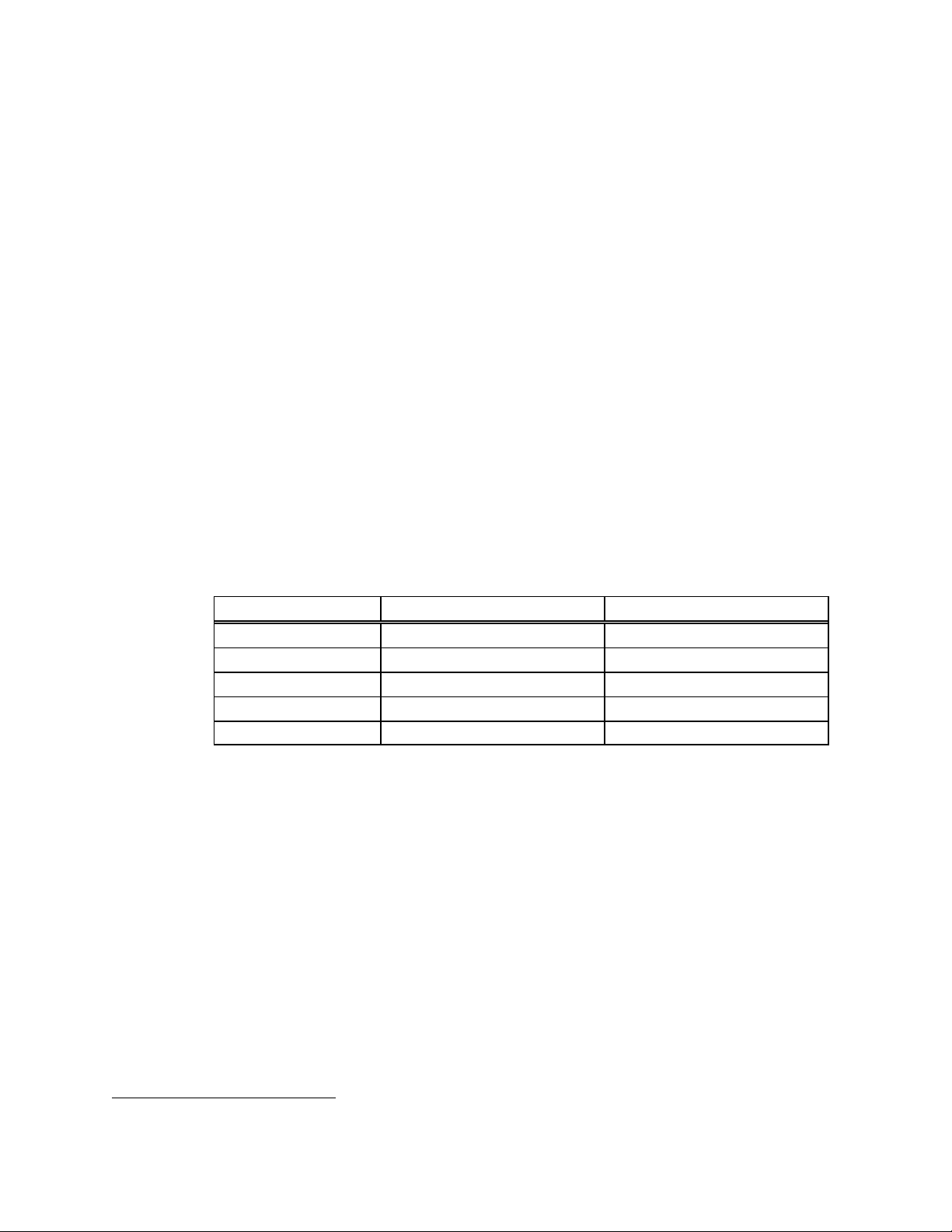
Video Resolution Number of Bits/Color Number of Colors
640 x 400 6 262,144
640 x 480 6 262,144
720 x 400 6 262,144
800 x 600 6 262,144
1024 x 768 6 262,144
For IBM VGA1 modes, the Monitor will accept 640 pixels horizontally; 400 or 480 lines vertically
and 800 pixels or 1024 pixels horizontally, 600 lines or 768 lines vertically for the VESA2 modes.
Figure 9 defines the video signal timing requirements.
The LCD Controller B oard will automatically program itself, sensing incoming horizontal/vertical
frequencies and sync pulse polarities to completely “fill” the active display area of the Monitor
with the video resolution being presented. Section 4.4.1 (Video Mode Definition s) defines
parameters for video resolution detection by the LCD Controller Board.
Note: IBM VGA1 modes with border and the 720 x 400 video resolution are excluded from
completely filling the active display area horizontally. Only the first 640 pixels will be displayed.
1
IBM VGA is a registered trademark of International Business Machines Corporation
2
VESA is a registered trademark of Video Electronics Standards Association.
Title: Product Specification: LC12 High-Bright Monitor Page 4 of 24
Document Number: 023-0284-01 Revision: A
Page 5

2.0 Basic Construction
2.1 Weight
Monitor weight does not exceed 5 Kgs (11 lbs).
2.2 Mechanical Mounting Requirements
Per Planar Mechanical Outline drawing 074-0666-01
2.3 Monitor Electronics
Electronic components requiring heat sinks are installed independent of the Monitor enclosure.
That is, its sheet metal chassis is not used as a heat sink for any electronic component.
2.4 Cooling Fan
Cooling fans are installed to maintain appropriate internal operating temperatures when the
Monitor is subjected to its operating environment of Section 3. Forced air convection is used to
cool the LCD Panel (front and back).
2.5 Vandal Glass
The Monitor is designed to operate with a vandal glass 289 mm x212 mm x 10 mm in place. This
vandal glass in not provided with the Monitor.
2.6 Air Filtration
An air filter mesh is included to prevent ingress of insects and ensure continual flow of cooling air
within the Monitor. The air filter mesh is externally accessible for cleaning.
2.7 Connectors
There are two (2) connectors supplied as an integral part of the Monitor.
2.7.1 Video Signal Connector
2.7.2 DC Power Input Connector
The Monitor unit includes a chassis mounted 15-pin female mini D-Shell connector
(AMP 748390-5 or equivalent) with socket contacts at the rear of the Monitor. It is
shielded for electromagnetic interference (EMI) purposes. Refer to Section 4.1 for
electrical connections.
The DC power input connector is a chassis mounted 2-pin "MAT?N?LOK" style
connector (AMP 1-480699-0 or equivalent) with pin contacts at the rear of the
Monitor. Connections are insulated to insure no accidental contact.
Title: Product Specification: LC12 High-Bright Monitor Page 5 of 24
Document Number: 023-0284-01 Revision: A
Page 6

2.8 LCD Controller Board
The LCD Controller Board incorporates components necessary to drive the LCD Panel (Section
6.7). Accepting VGA and VESA video standards (Section 1.2), these video signals are digitized and
processed for the LCD Panel. Due to the LCD Panel’s fixed video resolution (800 x 600), the LCD
Controller Board will perform independent horizontal and vertical zoom and shrink scaling of
specified video resolutions less than or greater than the LCD Panel’s video resolution to fully
accommodate the LCD Panel’s capability.
Magnification or reduction of specified video resolutions to match the native LCD Panel’s
resolution incorporates scaling algorithms minimizing aliasing and image distortion. The LCD
Controller Board includes the following characteristics:
• Per pixel scaleable filters providing text sharpening and graphics smoothing for improved
image quality.
• Color depth enhancement by performing spatial-temporal dithering reducing visual artifacts.
2.9 Grounding
Two (2) types of ground are provided: Chassis and Signal ground.
2.9.1 Chassis Ground
The chassis ground is a conductor that is grounded to the earth within user circuitry.
It is not used for current carrying purposes. It is used only for non-current carrying
purposes such as electromagnetic compatibility (EMC).
2.9.2 Signal Ground
Signal ground is electrically connected to chassis ground via the LCD Panel.
However, there are no DC currents carried through this interconnect.
2.10 External And Internal Controls
A single external “Video Gain” control compensates for the white state (full white) video signal
level range specified in Section 4.2.1 in achieving sixty-four (64) shades of gray.
External horizontal and vertical image positioning control(s) are provided to accommodate for
the undefined delay between sync and video data edge referred to as Front Porch / Back Porch in
Figure 9.
Title: Product Specification: LC12 High-Bright Monitor Page 6 of 24
Document Number: 023-0284-01 Revision: A
Page 7
3.0 Environmental
3.1 Temperature and Humidity
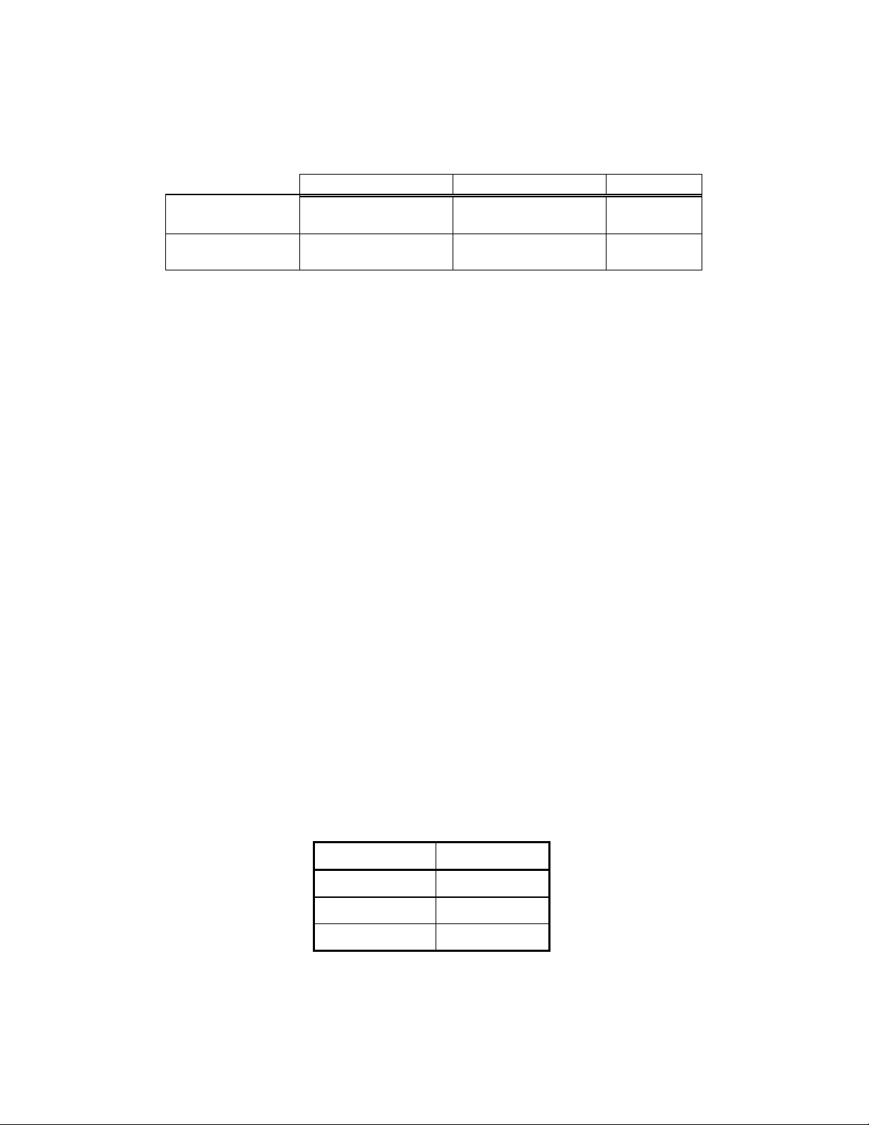
The Monitor withstands operating and storage environmental conditions liste d in Table 1.
General Operating Shipping and Storage Comments
Temperature
Relative Humidity Note 1,4 Note 1
Table 1. Temperature / Humidity Limits.
Tair is defined as ambient air temperature surrounding Monitor.
Note 1: Tair < 32°C : 95% RH maximum.
Tair > 32°C : Absolute humidity content not to exceed 100% at 32oC.
Note 2: Tair @ -20°C < 48 hours
Tair @ 60°C < 168 hours
0oC to 60oC
[32oF to 140oF]
? -20oC to 60oC
[? -4oF to 140oF] Note 2,3,4,5
Without
Condensation
Note 3: Slight background color changes are allowed depending on ambient temperature.
This phenomenon is reversible.
Note 4: Tair @ -30°C : 15% RH (exterior face of Vandal Shield)
Tair @ 54°C : 100% RH (exterior face of Vandal Shield)
Note 5: Upper operating temperature limit of 60°C is without solar loading. See section 3.2
for operating temperature conditions with solar load.
Reference to "room ambient" is interpreted as 20°C - 25°C [68°F -? 77°F] and applies throughout
this specification unless otherwise noted.
Excluding the exterior face temperature range of the Vandal Shield (Note 4), this Monitor will not
be subjected to environments outside of the limits of Table 1.
For product reliability predictions, the assumed temperature profile is:
Operating Time Temperature
5% 0°C [32°F]
90% 30°C [86°F]
5% 60°C [140°F]
3.2 Solar Loading
The Monitor is useable in an environment consisting of a 50 o C ambient air temperature and the
following input solar power.
Title: Product Specification: LC12 High-Bright Monitor Page 7 of 24
Document Number: 023-0284-01 Revision: A
Page 8
Power spectrum is referenced per MIL STD 810 E Environmental Test Method 505.3, Table -II
Spectral Energy Distribution and permitted tolerances
Maximum solar power flux = 1120 watts/m2 at 65 degrees normal to the Monitor surface.
These values assume no solar radiation attenuation from the customer-supplied vandal shield.
3.3 Altitude
Maximum operating altitude is 3,000 meters [9,850 feet]. Maximum shipping and storage
altitude is 12,000 meters [39,400 feet].
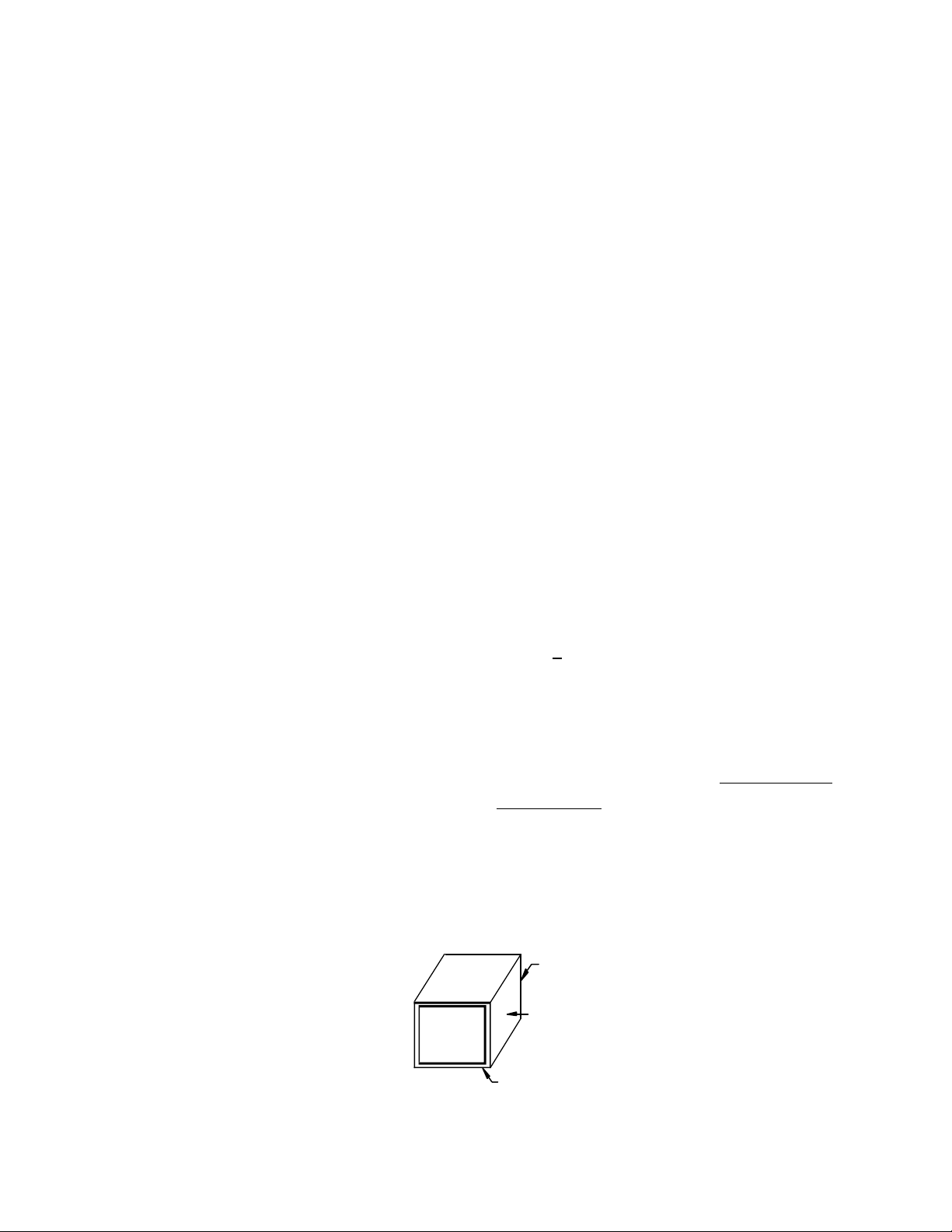
3.4 Mechanical Vibration and Shock
Note: Tests performed with unpackaged Monitors are mounted in a Planar approved rigid
retaining fixture.
3.4.1 Vibration
Non-Operating (sinusoidal): 10-200 Hz, 0.9g acceleration, 120 seconds per
sweep for 15 minutes, three axes, (x, y, z).
Following exposure unit shall meet all
performance requirements.
Non-operating (random): 10-200 Hz, 0.02g2/Hz, 10 min/axis, three (x, y, z).
3.4.2 Shock
Non-operating: 30 g, > 2.5 ms duration, ½ sine, 1 shocks per axis.
3.4.3 Shock Packaged Product
Non-operating: 30 inch free fall or simulated drop, 1 drop per side, 6
Following exposure unit shall meet all
performance requirements.
Following exposure unit shall meet all
performance requirements.
sides and 1 drop per edge, 3 edges 1 shocks per axis.
With accelerometer attached to center of product
display screen, a maximum of 50 G’s is allowed.
Following exposure unit shall meet all performance
requirements.
Y (rear)
X (side)
DISPLAY
Z (bottom)
Figure 3. Monitor unit orientation 1
Title: Product Specification: LC12 High-Bright Monitor Page 8 of 24
Document Number: 023-0284-01 Revision: A
Page 9

4.0 Video Signal Input Requirements
4.1 Video Input Lines
The Video Signal Connector consists of fifteen (15) positions wired numerically and supplied
attached to the Monitor as a chassis mounted connector per definitions listed in Table 2. The
"NC" positions of this connector are not used for any purpose.
Pin Number Signal Name
1 Red Video
2 Green Video
3 Blue Video
4 Monitor Sense Line 3
5 NC
6 Red video return
7 Green video return
8 Blue video return
9 NC
10 Signal Ground Reference
11 Monitor Sense Line 1
12 Monitor Sense Line 2 (NC)
13 Horizontal Sync Input
14 Vertical Sync Input
15 NC
(connected to Pin 10)
(connected to Pin 10)
Table 2. Video Signal Connector – Pin Number Assignments
The Video Signa l Connector that connects to the customer’s equipment is a female 15-pin
connector in a high density 9-pin D-Shell housing. Pin number assignments are defined in Table
2, and physical layout as seen by the interface cable from user logic is shown in Table 4.
Figure 4. Video Signal Connector Illustration
4.2 Signal Functions
4.2.1 Video Parameters
As seen by the source, input resistance is 75-ohm, ±10%; input capacitance at (150
MHZ) <10-pF.
Coaxial cable is provided for video signal line(s) to match impedances and fo r EMI
attenuation. The video input signal will have a range of 0-mv to 714-mv (maximum)
Title: Product Specification: LC12 High-Bright Monitor Page 9 of 24
Document Number: 023-0284-01 Revision: A
Page 10

where 0-mv is minimum luminance. Rise and fall times for the input signal (10% 90%) will be ?5-ns (Figure 6).
When terminated with a 75-ohm termination, the dark sta te (black level) is defined
as a level between 0-mv and 10-mv. The white state (full white) is dependent on the
VGA controller driving the Monitor. Maximum levels may range from 550-mv to 714mv. Nominal 680-mv input voltage shall be defined as the default for supplier setup
requirements.
Displayed image intensity and colors will change linearly with the video analog
input. This is necessary to provide a uniform user color change on the screen in
response to a uniformly stepped analog input. The Monitor must be capable of
resolving a minimum color range of 262,144 displayable colors (6 bit resolution for
Red, Green and Blue). This interpolates to 64 shades of gray (or color) at the Red,
Green, and Blue analog video inputs. Accomplishing specified shades of gray
requires a “Video Gain” control adjustment (Section 15.0 ) of Red, Green, and Blue
analog input signals based on the maximum output level range previously specified.
POS
NEG
RISE
TIME
Figure 5. Rise / Fall Time
4.2.2 Synchronization
Sync pulses for horizontal and vertical are TTL levels. Figure 8 defines the levels and
drive current capabilities.
OVERSHOOT
FALL
TIME
HIGH
STEADY
LEVEL
LOW
STEADY
LEVEL
Title: Product Specification: LC12 High-Bright Monitor Page 10 of 24
Document Number: 023-0284-01 Revision: A
Page 11
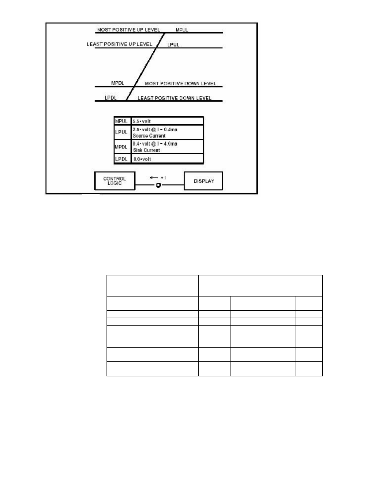
Figure 6. TTL Allowable Signal Levels
4.2.2.1 Mode Detection
The polarity of incoming horizontal/vertical frequencies and synchronization pulses
define the video resolution being presented. Video modes are listed in Table 3.
Video Mode Displayed
Image
Resolution
Horizonta
IBM VGA 640 x 400 31.468 70 - +
IBM VGA 640 x 480 31.468 60 - IBM VGA
w/Border
IBM VGA 720 x 400 31.468 70 - -
IBM VGA
w/Border
VESA 800 x 600 48.077 72 + +
VESA 1024 x 768 56.48 70 - -
Table 3. Video Mode Definitions
4.2.2.2 Color Display Detection
The vide o signal source determines which type of display is connected to it
based on the state of the Monitor Sense Lines. The Monitor will indicate to
the source that it is a "color display" when Monitor Sense Line 1 (Pin 11) is
656 x 496 31.468 60 -
738 x 414 31.468 70
Scanning Frequency)
Vertical
l (KHz)
(Hz)
Sync Polarity
Horizontal Vertical
-
Title: Product Specification: LC12 High-Bright Monitor Page 11 of 24
Document Number: 023-0284-01 Revision: A
Page 12

4.3 Signal Quality
4.3.1 TTL Sync Pulse Signal Levels
Input levels for the horizontal and vertical sync pulses are defined in Figure 8.
4.3.2 Rise and Fall Times
Rise and fall times are the times required for signal transitions between 10% of Vs
above Low Steady Level and 10% of Vs below High Steady Level where Vs is the
peak-to-peak video input signal level. The overshoot, if present, shall be exempted
from establishing these high/low levels referenced in. Both rise and fall times of each
input signal shall be as follows:
Video: Less than 5-ns
Horizontal Sync: Less than 50-ns
Vertical Sync: Less than 100-ns
physically connected to Signal Gr ound Reference (Pin 10) as defined by the
wiring definitions of Table 2.
4.4 Timing and Frequency
4.4.1 Video, Horizontal And Vertical Sync
Figure 6 illustrate video timin g relationships the Monitor operates within when the
specified video mode (per Table 3) is applied.
Front Porch defines the time from end of active video data to the start of Horiz/Vert
Sync Pulse.
Back Porch defines the time from end of Horiz/Vert Sync Pulse to the start of active
video data.
Blanking is the total time comprising Front Porch, Back Porch and Sync Pulse time(s).
The horizontal sync circuitry synchronizes to horizontal frequencies of 31.468 KHz
±0.5 KHz, 48.077KHz ±0.5KHz, and 56.476KHz ±0.5KHz. Horizontal sync pulse width
variation is 1.813-µsec to 3.813-µsec. The Monitor will "sync" to the specified format
vertical frequencies between 60Hz ?72Hz without adjustment.
Absence of Horizontal and/or Vertical Sync will not damage the Monitor nor violate
EMI radiation limits specified herein.
Title: Product Specification: LC12 High-Bright Monitor Page 12 of 24
Document Number: 023-0284-01 Revision: A
Page 13

4.5 Video S ignal On-Off Sequences
The sequence for bringing up and removal of each video input signal can be in any sequence or
combination of input signals.
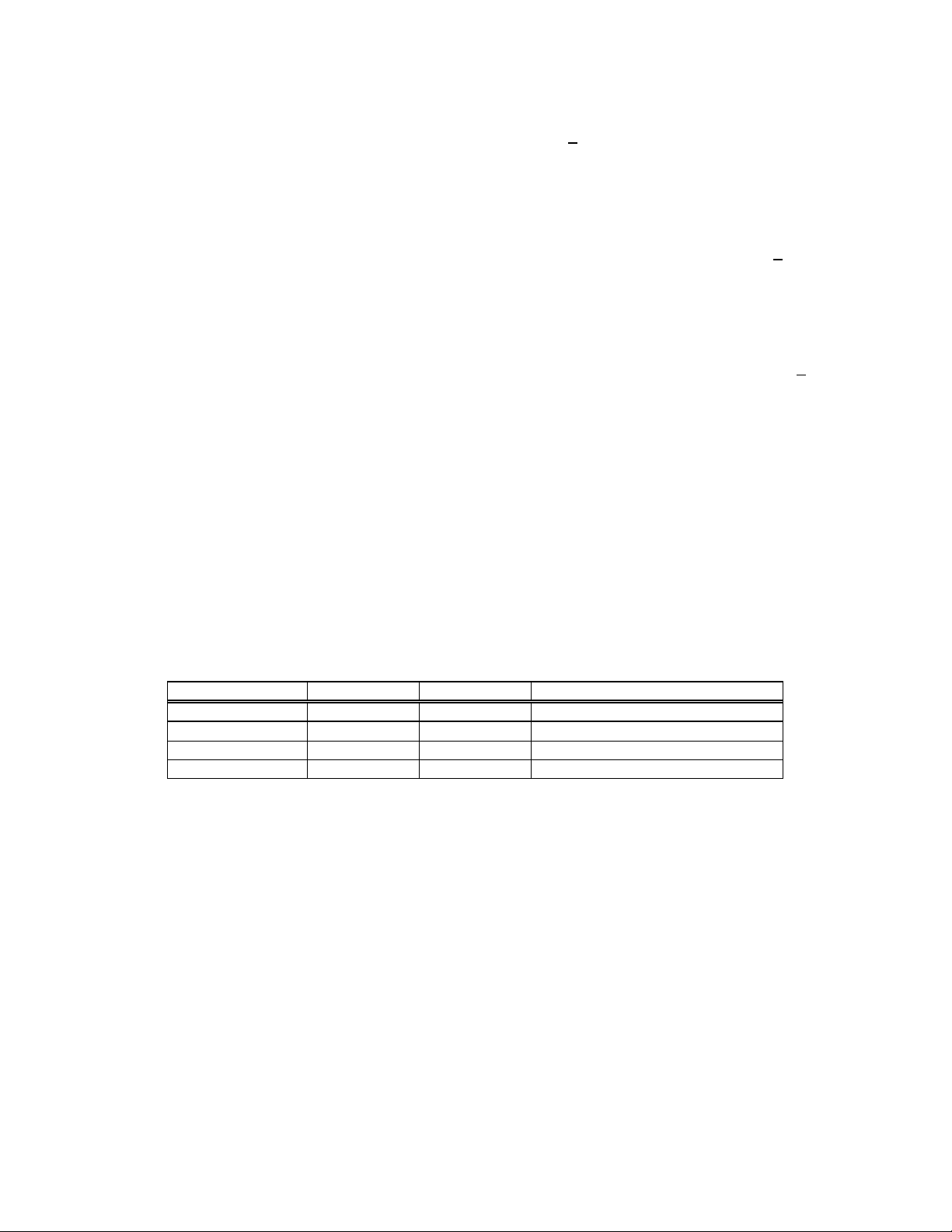
Video Modes
IBM VGA VESA
Resolution 640x400 640x480 800x600 1024x768
Video Clock 25.175 MHz 25.175 MHz 50.000 MHz 75.000 MHz
Horizontal Scan
Freq. 31.468 KHz 31.468 KHz 48.077 KHz 56.476 KHz
Horizontal Line
Period
Horizontal
Blanking 6.356 us 160 pixels 6.356 us 160 pixels 4.800 us 240 pixels 4.053 um 304 pixels
Horizontal Sync
Pulse 3.813 us 96 pixels 3.813 us 96 pixels 2.400 us 120 pixels 1.813 us 136 pixels
Horizontal Front
Porch 0.636 us 16 pixels 0.636 us 16 pixels 1.120 us 56 pixels 0.320 us 24 pixels
Horizon tal Back
Porch 1.907 us 48 pixels 1.907 us 48 pixels 1.280 us 64 pixels 1.920 us 144 pixels
Horizontal Active
Display 25.422 us 640 pixels 25.422 us 640 pixels 16.000 us 800 pixels
Horizontal Sync
Polarity - - - Vertical Scan Freq. 70.087 Hz 59.94 Hz 72.184 Hz 70.069
Vertical Frame
Period 14.268 ms 449 lines 16.683ms 525 lines 13.853 ms 666 lines 14.272 ms 806 lines
Vertical Blanking 1.557 ms 49 line 1.430 ms 45 line 1.373 ms 66 lines 0.673 ms 38 lines
Vertical Sync Pulse 0.064 ms 2 lines 0.064 ms 2 lines 0.125 ms 6 lines 0.106 ms 6 lines
Vertical Front
Porch 0.381 ms 12 lines 0.318 ms 10 lines 0.770 ms 37 lines 0.053 ms 3 lines
Vertical Back Porch 1.112 ms 35 lines 1.049 ms 33 lines 0.478 ms 23 lines 0.514 ms 29 lines
Vertical Active
Display 12.711 ms 400 lines 15.254 ms 480 lines 12.480 ms 600 lines 13.599 ms 768 lines
Vertical Sync
Polarity - - - -
Note: VGA border is not included in the Active Display time described above.
31.778 us 800
pixels
31.778 us 800
pixels
20.800 us 1040
pixels
17.707 us 1328
pixels
13.653 us 1024
pixels
Title: Product Specification: LC12 High-Bright Monitor Page 13 of 24
Document Number: 023-0284-01 Revision: A
Page 14

31
800
20
1040
6
160
4
240
3
96
96
2
120
0
16
16
1
56
1
48
48
1
64
25
640
16
800
14
525
13
666
1
49
1
45
1
66
0
2
0
2
0
6
0
12
0
10
0
37
1
35
1
33
0
23
12
480
12
600
VIDEO MODES
RESOLUTION
Video Clock
Horizontal Scan Frequency
Horizontal Line Period
Horizontal Blanking
Horizontal Sync Pulse
Horizontal Front Porch
Horizontal Back Porch
Horizontal Active Display
Horizontal Sync Polarity
Vertical Scan Frequency
Vertical Frame Period
Vertical Blanking
Vertical Sync Pulse
Vertical Front Porch
Vertical Back Porch
Vertical Active Display
Vertical Sync Polarity
Note: For video mode 720 x 400 missing video rows and columns are allowed. This is a text mode
640 x 400
25.175 MHz
31.468 KHz
.778 µs
.356 µs
.813 µs
.636 µs
.907 µs
.422 µs
-
70.087 Hz
.268 ms
.557 ms
.064 ms
.381 ms
.112 ms
.711 ms
+
IBM VGA
640 x 480
25.175 MHz
31.468 KHz
800 dots 31 .778 µs
160 dots 6 .356 µs
dots 3 .813 µs
dots 0 .636 µs
dots 1 .907 µs
640 dots 25 .422 µs
449 line 16 .683 ms
line
line
line
line
400 line 15 .254 ms
.430 ms
.064 ms
.318 ms
.049 ms
dots
dots
dots
dots
dots
dots
- +
59.94 Hz
line
line
line
line
line
line
- +
.800 µs
.800 µs
.400 µs
.120 µs
.280 µs
.000 µs
.853 ms
.373 ms
.125 ms
.770 ms
.478 ms
.480 ms
VESA
800 x 600
50.000 MHz
48.077 KHz
dots
dots
dots
dots
dots
dots
72.187 Hz
line
line
line
line
line
line
only. Performance is acceptable if characters as defined section 1.2.1 are legible. Missing row or
columns at edge of display is acceptable as long as characters remain legible.
Title: Product Specification: LC12 High-Bright Monitor Page 14 of 24
Document Number: 023-0284-01 Revision: A
Page 15
5.0 DC Power Input Requirements
5.1 DC Power Input Lines
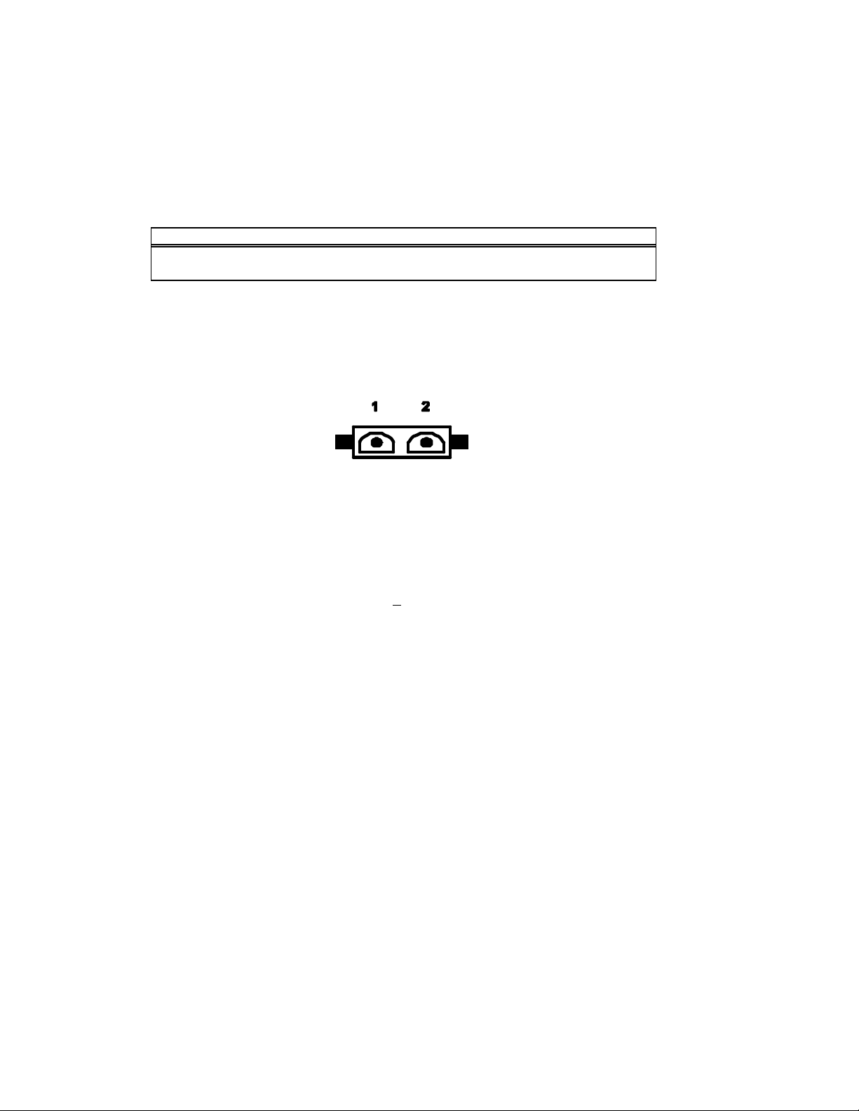
The DC Power Input Connector consists of two (2) positions wired numerically and supplied
attached to the Monitor as a chassis mounted connector per definitions listed in.
PIN NUMBER SIGNAL NAME
1 Most Positive Input Voltage
2 Most Negative Input Voltage
Figure 10. DC Power Input Connector- Pin Assignments
The DC Power Input Connector is a 2 pin MAT-N-LOK type with male pin contacts AMP 1 480699.
Pin number assignments are defined in Figure 11; shown below is the physical layout as seen by
the interface cable from the DC power source.
Figure 8. DC Power Input Connector Illustration
5.2 DC Input Voltage / Current
DC Input Voltage: 12 vdc nominal, + 0.4 vdc.
Over the specified input voltage range:
Refer to Figure 12 for required current profile characteristics at “power–up” conditions.
The Monitor is not damaged by input voltages ranging from 0-vdc to 12.4-vdc".
- No loss of image synchronization occurs.
- White display luminance level is within 10% of luminance at nominal input
voltage.
- DC Input Current: 4.3 amp maximum current draw (12.4-vdc applied) steady
state conditions.
Title: Product Specification: LC12 High-Bright Monitor Page 15 of 24
Document Number: 023-0284-01 Revision: A
Page 16
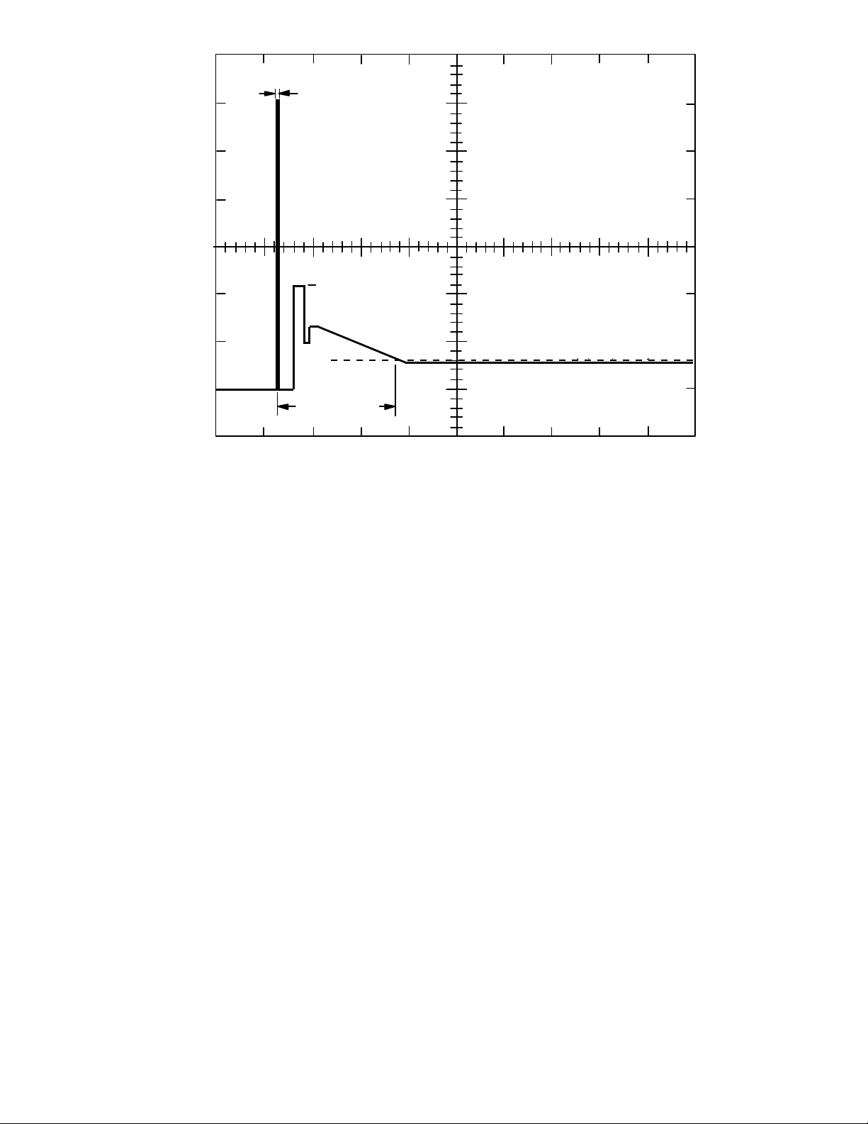
1-msec (max)
4.3 amp (max) steady
-
state
Initial inrush current
Power Supply Limit
25-amp
20-amp
15-amp
11-amp (max)
25-msec (max)
Stabilization
Figure 9. Current Profile: Note 3 amp figure is incorrect; use 4.3 amp as specified above.
5.3 Power On -Off Sequences
The Monitor will automatically return to normal operation upon resumption of power after a
power loss.
6.0 Display Performance
6.1 Display Luminance
3-amp (max) steady-state
Time Scale: 10-msec / div
10-amp
5-amp
0-amp
The display provides one level of luminance used for both daylight and night viewing.
Minimum white -light luminance at the screen center of the Monitor face is 1500 cd/m2 [467 fL] in
a darkened room environment with ambient light conditions less than 10 LUX [1fC] incident
illumination and at room temperature. Reference: MIL-L-85762A (3.10.2.2.3). Luminance
specification applies to the initial luminance, i.e. prior to additional operation in the end system.
Luminance
? > 1,500cd/m2 [467 fL]
min
6.2 Display Contrast
Display contrast is a relationship between luminance levels and the ability to perceive a
luminance difference. It is expressed as a ratio of ON white – luminance to OFF black background
luminance generated by the display.
Title: Product Specification: LC12 High-Bright Monitor Page 16 of 24
Document Number: 023-0284-01 Revision: A
Page 17
6.2.1 Room Ambient Contrast
Minimum Contrast of the display under room ambient lighting conditions of 1076
LUX [100 fC] direct incident illumination, is > 90:1. Reference MIL-L-85762A (Table II).
6.2.2 High Ambient Contrast
Minimum Contrast of the display in a diffuse off-axis illumination of 86,080 LUX
[8,000 fc] and a specula r on axis luminance (sky) of 6,853 cd/m2 [2000 fL] is > 6:1.
Reference MIL-L-85762A (Table II).
6.3 Display Uniformity
Luminance Uniformity (UL) measured within 30 mm from edge of the display image area is + 40%
of the luminance measured at the center of the display screen.
6.4 Display Chromaticity
The metric used for color coordinate determination is the CIE 1976 UCS (Uniform Chromaticity
Scale) u’, v’ system.
Color determination is performed normal to the display in a dark room environment with
ambient light conditions less than 10 LUX [1fC] incident illumination.
The measured u’, v’ color coordinates at room temperature for White -light and the Red, Green,
and Blue primaries are listed for reference purposes only.
Color u? v? Perceived Color
Red 0.449 0.517 Red
Blue 0.144 0.299 Blue
Green 0.142 0.559 Yellowish-Green
White 0.215 0.489 Warm White
White color is concentrated around 5600oK color temperature.
6.5 LCD Panel - Physical Image Characteristics
• The Monitor incorporates a matrix display with the followin g features:
• LCD Size: 307.5mm [12.11in] diagonal
• Active Area: 246.0mm [9.69in] by 184.5mm [7.26in]
• Pixel Format: 800 (H) x 600 (V) (1 full color pixel = R + G + B dots)
• Pixel Pitch: 0.3075mm [0.012in] horizontal x 0.3075mm [0.012in] vertical
• Pixel Arra ngement: R,G,B vertical stripe
Title: Product Specification: LC12 High-Bright Monitor Page 17 of 24
Document Number: 023-0284-01 Revision: A
Page 18
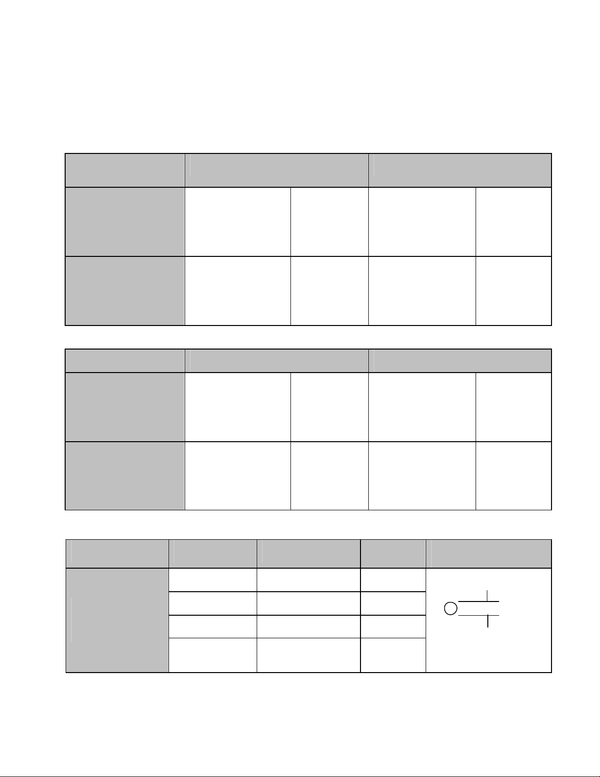
7.0 Display Cosmetics
All defects, pixel related and non-pixel related are observed at 46 cm [18”] viewing distance under room
ambient light intensity 400-600 lux (fluorescent or incandescent lighting). Viewing time is specified as 5
seconds. The following criteria applies to active area of display.
Random Single Pixel
Defects
Bright Defects (Pixels)
White Screen
Dark Defects (Pixels)
Black Screen
Adjacent Pixel Groups Qty Allowed (Pairs) Qty Allowed (Triplets)
Bright Defects (Pixels)
White Screen
Qty Allowed Separation Allowed
Red, Green, Blue Max. 10 Red, Green
Red, Blue
Green, Blue
Red, Green, Blue Max. 10 Red, Green
Red, Blue
Green, Blue
Red, Red
Max. 2
Green, Green
All colors
Blue, Blue
Red, Red, Red
Blue, Blue, Blue
Green, Green, Green
Min. 0.200”
Min. 0.200”
Min. 0.200”
Min. 0.040”
Min. 0.040”
Min. 0.040”
Max. 0
All colors
Dark Defects (Pixels)
Black Screen
Non-Pixel Defects Qty Allowed Size Separation
Circular Dark Defects
Contamination
Title: Product Specification: LC12 High-Bright Monitor Page 18 of 24
Document Number: 023-0284-01 Revision: A
Red, Red
Green, Green
Blue, Blue
0 >.020” 1 .010 < D <.020” 4 .005” < D < - .010” .100”
Not cause for
rejection
Max. 4
All colors
<.005”
Red, Red, Red
Max. 0
Blue, Blue, Blue
All colors
Green, Green, Green
Defect Description
D
Page 19

Non-Pixel Defects Qty Allowed Size Separation
L > 0.120”
Bright Line Defects
Polarizer Scratch, Lint
Contamination
0
W > .010”
.020” < L < .120”
5
.002” < W < .010”
-
.100”
Defect Description
L
W
Not cause for
rejection
Notes: A bright spot is a subpixel which, when a black screen is being displayed, is visible through a 20%
transmission ND filter to an unaided eye at least 45 cm [18”] away from the display surface in a dark room.
Dark spots in which the dark spot area divided by the subpixel area is less than 1/3 are not counted.
L< .020”
W< .002”
8.0 Regulatory Agency Requirements
8.1 Safety Certification
The Monitor does not inhibit customer from certifying product to following safety standards:
UL 1950/CAN/CSA C22.2 No. 950-95 Safety of Information Technology, including electrical
business equipment
• UL 291Standard for Automated Teller Machine
• EN 60950 Safety of Information Technology, including electrical business equipment.
8.2 CE Marking (Declaration according to ISO/IEC Guide 22 and EN45014)
The Monitor does not inhibit customer from conforming to the following EC Directives:
Council Directive 73/23/EEC and 93/68/EEC (Latest Amendment) on the harmonization of the
laws of the Member States relating to electrical equipment designed for use within certain
voltage limits is based on compliance with the following harmonized standards:
• EN 60950 June 2000
• EN 41003:1991
Council Directive 89/336/EEC, 92/31/EEC and 93/68/EEC (Latest Amendment) on the
approximation of the laws of the Member States relating to electromagnetic compatibility is
based on compliance with the following harmonized standards:
• Electromagnetic Emissions EN 55022 Class A: 1994
Title: Product Specification: LC12 High-Bright Monitor Page 19 of 24
Document Number: 023-0284-01 Revision: A
Page 20

• Electromagnetic Immunity EN 50082 part 1:1992
8.3 RFI Emission Certification
The Monitor is certified to the following emissions standards when installed i n customer product
configuration:
• FCC, Part 15, Paragraph 15.107(b) and 15.109(b), Class A RFI emissions standard.
• EN 55022 Class A: 1994 ? Limits and measurements of radio interference characteristics of
information technology equipment.
• IEC 1000 3-?2/1995; EN 61000-?3-?2 Current Harmonic Tests
• IEC 1000 3-?3/1995; EN 61000-?3-?3 Voltage Fluctuation and Flicker Tests
8.4 System Transient Disturbance Requirements
The Monitor meets the following system transient disturbance requirements:
8.4.1 Electrostatic Discharge
The Monitor performs normally when subjected to static electricity discharges from
persons touching the external surfaces of the Monitor. Performance is verified by
testing according to EN 50082-1 (Ref IEC 801-2:1984) at severity level 3 (4 Kv contact
discharge, 8 Kv air discharge).
8.4.2 Electromagnetic Energy Susceptibility Requirements
The Monitor performs normally in an electromagnetic field with a strength of 10volts per meter from 10 KHz to 1 GHz. (REF CISPR 22).
The Monitor with appropriate cables is designed to comply with applicable EMC and
Safety standards as noted in sections 2.31 and 2.3.2.
8.5 Labeling
Where applicable, the Monitor complies with IEC 60417 – Graphical Symbols for Use on
Equipment
8.6 Color Coding
Where applicable, the Monitor complies with ISO 3864 – Safety colors and Safety Signs
9.0 Reliability
9.1 Design Workload
The Monitor is capable of operating 24 hours a day, 365 days a year under the specified
environmental conditions per section 3.1.
Title: Product Specification: LC12 High-Bright Monitor Page 20 of 24
Document Number: 023-0284-01 Revision: A
Page 21

9.2 Critical Failures
Critical failures is defined as failures that render the Monitor inoperable to the end user. The
MTBCF (Mean Time Between Critical Failures) value excludes the fluorescent backlight assembly
which requires periodic replacement and assumes periodic cleaning of air filtration screens to
ensure adequate air flow for cooling.
The Monitor MTBCF is > 40,000 hours.
Note: MTBCF excludes fluorescent tubes from calculation. Calculation is made per MIL Reliability
Handbook 217 Method 3.
9.3 Failure Definition
In general, the term failure denotes a fully functional Monitor unit ceasing to function within its
required performance capability because of conditions internal to the Monitor unit. The
requirements of Section refer to critical failures, defined and distinguished from others as
follows:
Monitor Fa ilure - Monitor ceases full operation. The failure cannot be corrected without at least
one of the following: tools, test equipment, replacement parts, checks of the Monitor unit, and
knowledge beyond performing routine operations.
Nuisance Failure - A component in the Monitor unit has ceased operation but does not impair
the required operation of the unit.
Not Machine Failures - Malfunctions attributable to the following causes shall not be classified
as failures:
• Improper installation or maintenance
• Abuse or misuse
• Exposure to environments outside the specified design range.
• Lack of prescribed preventative maintenance.
• Failures caused by test equipment used to control cycle and check the operation of Display
units on test.
10.0 Description of Warranty
Seller warrants that the Goods will conform to published specifications and be free from defects in material for 12
months from delivery. To the extent that Goods incorporate third-party-owned software, Seller shall pass on Seller's
licensor's warranty to Buyer subject to the terms and conditions of Seller's license.
Warranty repairs shall be warranted for the remainder of the original warranty period. Buyer shall report defect claims
in writing to Seller immediately upon discovery, and in any event, within the warranty period. Buyer must return
Goods to Seller within 30 days of Seller’s receipt of a warranty claim notice and only after receiving Seller’s Return
Goods Authorization. Seller shall, at its sole option, repair or replace the Goods.
If Goods were repaired, altered or modified by persons other than Seller, this warranty is void. Conditions resulting
from normal wear and tear and Buyer's failure to properly store, install, operate, handle or maintain the Goods are not
within this warranty. Repair or replacement of Goods is Seller’s sole obligation and Buyer's exclusive remedy for all
Title: Product Specification: LC12 High-Bright Monitor Page 21 of 24
Document Number: 023-0284-01 Revision: A
Page 22

claims of defects. If that remedy is adjudicated insufficient, Seller shall refund Buyer's paid price for the Goods and
have no other liability to Buyer.
All warranty repairs must be performed at Seller’s authorized service center using parts approved by Seller. Buyer shall
pay costs of sending Goods to Seller on a warranty claim and Seller shall pay costs of returning Goods to Buyer. The
turnaround time on repairs will usually be 30 working days or less. Seller accepts no added liability for additional days
for repair or replacement.
If Seller offers technical support relating to the Goods, such support shall neither modify the warranty nor create an
obligation of Seller. Buyer is not relying on Seller’s skill or judgment to select Goods for Buyer’s purposes. Seller’s
software, if included with Goods, is sold as is, and this warranty is inapplicable to such software.
SELLER DISCLAIMS ALL OTHER WARRANTIES, EXPRESS OR IMPLIED, INCLUDING BUT NOT LIMITED TO, IMPLIED
WARRANTIES OF MERCHANTABILITY AND FITNESS FOR A PARTICULAR PURPOSE
11.0 Support and service
Planar is a US company based in Beaverton, Oregon and Espoo, Finland with a worldwide sales distribution
network. Full application engineering support and service are available to make the integration of Planar
displays as simple and quick as possible for our customers.
RMA Procedure: For a Returned Material Authorization number, please contact Planar Systems, Inc., with the
model number(s) and original purchase order number(s). When returning goods for repair, please include a brief
description of the problem, and mark the outside of the shipping container with the RMA number.
Planar Systems, Inc.
Customer Service
24x7 Online Technical Support: http://www.planar.com/support
Americas Support
1195 NW Compton Drive
Beaverton, OR 97006-1992
Tel: 1-866-PLANAR1 (866) 752-6271
Hours: M-F, 5am - 5pm Pacific Time
Europe and Asia-Pacific Support
Olarinluoma 9 P.O. Box 46
FIN-02201 Espoo, Finland
Tel: +358-9-420-01
Hours: M-F, 7:00am - 4pm CET
12.0 Glossary of Terms and Abbreviations
Aspect Ratio: The ratio of width to height of a display surface. The standard television aspect ratio is 4:3.
Back Porch : The portion of a composite display signal which lies between the trailing edges of a
horizontal sync pulse and the corresponding blanking pulse.
Black Level: The display-signal level corresponding to a specified limit for black peaks.
Blanking: The process of decreasing (or inc reasing) the display-signal level so that no visible retrace will
appear on the display screen.
Blanking Level?? The level of a composite display signal which separates the range containing display
information from the range containing synchronizing information. Also called the pedestal level, or
blacker-than-black.
Brightness: A psycho-physiological attribute of visual perception in which a source appears to emit or
reflect more or less light. Its psycho-physical, photometric equivalence is luminance.
Candela -per-meter-squared [cd/m2]: The international unit of luminance (nits).
Candle Power: Luminous intensity expressed in candelas.
Title: Product Specification: LC12 High-Bright Monitor Page 22 of 24
Document Number: 023-0284-01 Revision: A
Page 23

CIE: Abbreviation for the Commission Internationale de l'Eclairage, formerly referred to as the
International Commission on Illumination (ICI).
Chrominance: The colormetric difference (dominant wavelength and purity) between any color and a
reference "white" of equal luminance. In three-dimensional CIE color space, chrominance is a vector
which lies in a plane of constant luminance.
Chromaticity: The color quality of light which is defined by its dominant wavelength and purity (see
Chrominance).
Chromaticity Value: The scalar value of any one component of a three-component color (also called a
tristimulus value). The unit value of each component is the amount of that component added to the
other two components to produce a reference "white".
Color Data: The programmed values which determine the amplitudes of the signal which drive a color
display.
Color Saturation : A psycho-physiological measurement of the degree to which a color appears to be
free of white light.
Color Temperature: The temperature to which a black body must be heated to produce a color
matching that of the source.
Contrast : The ratio between the maximum and minimum luminance values of a display.
dB (Decibel): A measure of the ratio of two signals. The dB value is 20 x log10 of a voltage or current ratio
or 10 x log10 of a power ratio.
Foot-Candle [fC]: A unit of illumination equal to the illuminati on which occurs when uniformly
distributed luminous flux is impinging on an area at a rate of one lumen per square foot.
Foot-Lambert [fL]: A unit of luminance equal to the uniform luminance of a perfectly diffusing surface
emitting or reflecting luminance flux at the rate of one lumen per square foot.
Front Porch : The portion of a composite display signal which lies between the leading edges of a
horizontal blanking pulse and the corresponding sync pulse.
Gray Scale : Variations in the luminance value of "white" light, from black to white. Shades of gray are
defined as gray-scale graduations that differ by the square root of 2.
Illuminance: The density of luminance flux impinging on a surface. It is the quotient of the flux divided
by the "apparent" or projected area of the surface.
Image: A displayed view of one or more objects or parts of objects.
Lambert: A unit of luminance equal to the uniform luminance of a perfectly diffusing surface emitting or
reflecting light at the rate of one lumen per squ are centimeter.
Luminance: Luminous intensity reflected or emitted by a surface in a given direction per unit of apparent
area. Measured in nits.
Lumen: The unit of luminous flux or rate of luminous energy flow. It is equal to the flux radiating
through a unit solid angle (steradian) from a uniform point source of one candela.
Luminous Flux: The time rate of luminous energy flow, measured by its capacity to evoke a visual
sensation. It is expressed in lumens.
Luminous Intensity: The luminous flux radiated by a point source. It is expressed in candela.
LUX: The international unit of illumination. One LUX equals one lumen per square meter.
MTBCF: Mean Time Between Critical Failure
Photometer???Any optical device which uses a comparison technique to measure luminous intensity,
luminance, or illumination. An equality-of-brightness photometer is based on simultaneous comparison
of adjoining visual areas; a flicker photometer compares successive stimuli in the same visual area.
Resolution : The number of addressable, controllable display or picture elements, or the number of
hypothetical coordinate locations which can be used to position graphic elements on a display surface.
Shades of Gray: A division of the gray scale from black to white into a series of discrete luminance
shades with a square -root-of-2 difference between successive shades.
Title: Product Specification: LC12 High-Bright Monitor Page 23 of 24
Document Number: 023-0284-01 Revision: A
Page 24

SVGA- Super Video Graphics Adapter
Sync: A contraction of synchronous or synchronization.
Tristimulus Value: See Chromaticity Value and Color Data.
VESA: Video Electronics Standards Association
VGA: Video Graphics Adapter
White: The common usage word for high -luminance achromatic colors.
XGA: Extended Graphics Adapter
13.0 Revision History
REV REF DATE PAGE DESCRIPTION OF CHANGE BY
A --- 14 Jan. 05 All First release S.Vahlsing
Title: Product Specification: LC12 High-Bright Monitor Page 24 of 24
Document Number: 023-0284-01 Revision: A
 Loading...