

Page 1

LA1910R and LA1910RTC Operations Manual www.planar.com
Page 2

2
Table of Contents
Usage Notice
Precautions . . . . . . . . . . . . . . . . . . . . . . . . . . . . . . . . . . . . . . . . . . . .3
Introduction
About the Product . . . . . . . . . . . . . . . . . . . . . . . . . . . . . . . . . . . . . . .4
Package Overview . . . . . . . . . . . . . . . . . . . . . . . . . . . . . . . . . . . . . . .6
Installation
Product Overview . . . . . . . . . . . . . . . . . . . . . . . . . . . . . . . . . . . . . . .7
User Controls
Front Panel Controls . . . . . . . . . . . . . . . . . . . . . . . . . . . . . . . . . . . .11
How to Use the OSD Menus . . . . . . . . . . . . . . . . . . . . . . . . . . . . . .12
On-Screen Display Menus . . . . . . . . . . . . . . . . . . . . . . . . . . . . . . . .13
Appendix
Troubleshooting . . . . . . . . . . . . . . . . . . . . . . . . . . . . . . . . . . . . . . . .17
Warning Signal . . . . . . . . . . . . . . . . . . . . . . . . . . . . . . . . . . . . . . .18
Product Dimensions . . . . . . . . . . . . . . . . . . . . . . . . . . . . . . . . . . . . .19
Compatibility Modes . . . . . . . . . . . . . . . . . . . . . . . . . . . . . . . . . . . .20
Touch Screen Driver Installation . . . . . . . . . . . . . . . . . . . . . . . . . . .21
Page 3

3
Precautions
Follow all warnings, precautions and maintenance as recommended in this
user’s manual to maximize the life of your unit.
Do:
Turn off the product before cleaning.
Use only a dry soft cloth or clean room wiper when
cleaning the LCD panel surface.
Use only high quality and safety approved AC/DC power
adapter.
Disconnect the power plug from AC outlet if the product
is not used for a long period of time.
Don’t:
Do not touch the LCD panel surface with sharp or hard
objects.
Do not use abrasive cleaners, waxes or solvents for
cleaning.
Do not operate the product under the following condi-
tions:
- Extremely hot, cold or humid environment.
- Areas susceptible to excessive dust and dirt.
- Near any appliance generating a strong magnetic field.
- Place in direct sunlight.
Usage Notice
WARNING – To prevent the risk of fire or shock hazards, do not
expose this product to rain or moisture.
WARNING – Please do not open or disassemble the product as this
may cause electric shock.
!
!
Page 4

4
Introduction
About Planar’s LA1910R / LA1910RTC
The LA19 is a 19” flat panel screen with an active matrix, thin-film transistor (TFT), liquid crystal display (LCD).
Features include:
Dual signal input: Analog VGA and Digital DVI-D
Active matrix TFT LCD technology
1280 x 1024 SXGA resolution
19” viewable display area
31.5 ~ 80 kHz horizontal scan
56 ~ 75 Hz refresh rate
0.294mm x 0.294mm pixel pitch
250 cd/m
2
(typ.) brightness
500:1(typ.) contrast ratio
L/R=85º/85º,U/D=85º/85º viewing angle, CR=10
Tr=15ms(typ.)/Tf=10ms(typ.) response time
CCFL backlight lamps w/30,000 hrs life
Auto-adjustment function
Multilingual OSD user controls
VESA DPMS power saving
Durable, capacitive touch screen ( for LA1910RTC)
Page 5

5
Touch Screen (for LA1910RTC)
Capacitive for finger interface
Optical Clarity: Up to 88% light transmission
Touch Contact Requirement: 3 ms for finger input
Surface Scratch Hardness: Cannot be scratched using any stylus
with Mohs' rating of less than 6.5.
Durability: Touch screen has been tested in a laboratory environ-
ment to withstand over 225 million mechanical touches without
noticeable degradation to the surface
Surface Obstructions: Touch screen's operation unaffected by
surface obstructions such as dirt, dust, grease, smoke, etc.
Chemical Resistance: Touch screen is highly resistant to corrosives,
in accordance with ASTM-D-1308-87 (1993) and ASTMD-F-1598-95.
Liquid Resistance: Liquids on screen do not impede touch screen
performance
Page 6
6
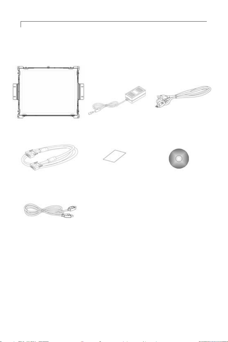
Package Overview
LCD Display Power Adapter Power Cord
VGA Signal Cable Quick Start Guide Touch Screen Driver
Installation CD-ROM
(for LA1910RTC)
LCD Display
Page 7
7
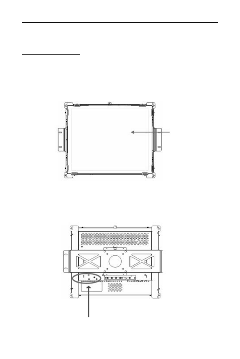
Installation
Product Overview
• Front View
• Rear View
LCD Display
Connector Ports “A&B”
Page 8

8
• Connector Ports “A”
• Connector Ports “B”
USB
(For LA1910RTC)
Page 9

9
Connecting the display (Figure 1.1)
To configure this monitor, please refer to the following figure and
procedures.
1. Be sure all equipment is off.
2. Connect the DC power cord to the power connector. Plug one end
of the AC power cord into the power adapter, and the other end into
an electrical outlet(1).
3. For the PC with Analog output: connect the VGA signal cable from
display VGA input connector to the 15-pin connector of your host
computer and tighten the screws(2).
4. Connect the USB cable from USB port of your display to the USB
port of your computer(3).
5. Turn on your computer, display and video source.
Notice: To ensure the LCD display works well with your computer, configure
the display mode of your graphic card, less than or equal to 1280 x
1024 resolution and make sure the timing of the display mode is compatible with the LCD panel. “Compatibility Modes” of this LCD panel
are listed in the appendices for your reference.
Page 10

10
Figure 1.1
Page 11

11
User Controls
Front Panel Controls
Displays the OSD menus
Select- To select the adjustment items
from OSD menus.
Auto- To activate the “Auto Adjustment”
function to obtain an optimum image
To adjust brightness press the “-” button
first
1. Decreases the brightness of the display image
2. Decreases value of the adjustment
items.
To adjust brightness press the “-” button
first
1. Increases the brightness of the display
image
2. Increases value of the adjustment
items.
Switches on/off the power of the LCD
display.
1. Green indicates the display is turned
on.
2. Amber indicates the display is in
power-saving mode.
Menu button
Select / Auto
Brightness Minus /
Minus
Brightness Plus /
Plus
Power Switch
Power LED
Page 12

12
How to Use the OSD Menus
1. Press the “Menu” button to pop up the on-screen menu and to select
between the four main menus.
2. Choose the adjustment items by pressing the “Select/Auto” button.
3. Adjust the value of the adjustment items by pressing the “ ” button.
Page 13

13
On-Screen Display Menus
First OSD Menu:
Auto-Adjustment
Choose this function to obtain an optimum image.
Contrast
This function allows the user to adjust the image crispness.
Contrast adjusts the difference between white and black shades.
Horizontal Position
Changes the horizontal position of the image.
Vertical Position
Changes the vertical position of the image.
Frequency
Changes the display data frequency to match the frequency of the
graphic card. When a vertical flickering bar is seen, use this function to make an adjustment.
Tracking
Synchronizes the signal timing of the display with the graphic card.
When you are experiencing unstable to flickering image, use this
function to make an adjustment.
Page 14

On-Screen Display Menus
Second OSD Menu:
Display Mode
Selects this function to view the display resolution, vertical refresh,
and horizontal scan of the current mode.
OSD Off-Time
Adjusts the time it takes for the OSD menu to disappear.
Language
Chooses the language you need.
Text-Graphic
Toggles between VGA text mode (mode M03H) and graphic mode
(mode M13H).
Sharpness
Adjust the sharpness of the image.
Reset
Returns the display parameters of the current mode to the factory
default settings.
14
Page 15

On-Screen Display Menus
Third OSD Menu:
Vo lume
Controls the sound volume.
Mute
Disables the sound immediately.
Video Source
Changes the video mode between multiple connections.
15
Page 16

On-Screen Display Menus
Fourth OSD Menu:
Color
Adjusts the color temperature.
Color Adjustment-Red
Adjusts the red color of the display.
Color Adjustment-Green
Adjusts the green color of the display.
Color Adjustment-Blue
Adjusts the blue color of the display.
16
Page 17

17
Appendix
Troubleshooting
If you are experiencing trouble with the LCD display, refer to the following. If
the problem persists, please contact your local dealer or visit Planar Support at
www.planar.com/support. See support contact information on rear cover.
Problem: No image appears on screen.
Check that all the I/O and power connectors are installed correctly
and well connected as described in the “Installation” section.
Make sure the pins of the connectors are not crooked or broken.
Problem: Partial image or incorrectly displayed image.
Check to see if the resolution of your computer is higher than that
of the LCD display.
Reconfigure the resolution of your computer to make it less than
or equal to 1280 x 1024.
Problem: Image has flickering vertical line bars.
Use “Frequency” to make an adjustment.
Check and reconfigure the display mode of the vertical refresh rate
of your graphic card to make it compatible with the LCD display.
Problem: Image is unstable and flickering
Use “Tracking” to make an adjustment.
Problem: Image is scrolling
Check and make sure the VGA signal cable (or adapter) is well con-
nected.
Check and reconfigure the display mode of the vertical refresh rate
of your graphic card to make it compatible with the LCD display.
Problem: Vague image (characters and graphics)
Use “Frequency” to make an adjustment. If the problem persists,
use “Tracking” to make an adjustment.
Page 18

18
Warning Signal
There are instances when you will see warning messages from the LCD screen.
This occurs when the LCD is unable to receive the exact signal from the computer graphic card.
There are three instances when this may happen. Please check the cable connections or contact your local dealer or Planar Support for more information.
No Signal
The LCD has been powered on but it isn’t receiving a signal from
the computer graphic card. Check all the power switches, power
cables, and VGA signal cable.
Going to Sleep
The LCD is under the power saving mode. In addition, the LCD will
go into this sleeping mode when experiencing a sudden signal disconnecting problem.
Unsupport Mode
The signal of the computer graphic card is incompatible with the
LCD. This occurs when the graphic card signal is not one of the
compatibility modes listed in the Appendices of this manual.
Page 19

19
Product Dimensions
Page 20

20
Compatibility Modes
IBM VGA
IBM VGA
IBM VGA
IBM VGA
VESA VGA
VESA VGA
VESA SVGA
VESA SVGA
VESA SVGA
VESA SVGA
VESA XGA
VESA XGA
VESA XGA
VESA SXGA
VESA SXGA
Apple Mac
Apple Mac
Apple Mac
Apple Mac
640 x 350
640 x 400
640 x 480
720 x 400
640 x 480
640 x 480
800 x 600
800 x 600
800 x 600
800 x 600
1024 x 768
1024 x 768
1024 x 768
1280 X 1024
1280 X 1024
640 x 480
640 x 480
832 x 624
1024 x 768
70
70
60
70
72
75
56
60
72
75
60
70
75
60
75
67
67
75
75
31.5
31.5
31.5
31.5
37.9
37.5
35.2
37.9
48.1
46.9
48.4
56.5
60.0
64.0
80.0
34.9
35.0
49.7
60.2
Mode
Resolution
V. Frequency
(Hz)
H.Frequency
(kHz)
Page 21

21
Touch Screen Driver Installation
Touch driver information is located on the enclosed CD-ROM for the following
operating systems: Windows Me/2000/98/XP series.
Driver Installation Process:
1. Before installing the touch driver be sure that the USB cable is dis-
connected from the LCD.
Please read "Readme.txt" before you start the installation
Please note: Once the CD-Rom is loaded into the PC, it should automatically
load the installation software. If not, follow steps 2-5 below.
2. Open the CD-Rom
3. Open the Touchware folder
4. Open the Disk 1 folder
5. Double click the "setup.exe" file
6. Follow the installation instructions
7. Connect the USB cable to the LCD.
8. If the touch screen driver does not automatically load, restart the
system.
Touch Panel Setting and Calibration:
1. Open the “Control Panel” of the system.
2. Double click the “Touch Panel” icon.
3. Select the item you want to set up and change the setting values.
Some setting changes are effective only when the system is rebooted.
Page 22

Planar Systems, Inc.
Customer Service
24x7 Online Technical Support:http://www.planar.com/support
Americas Support
Te l: 1-866-4PLANAR (866-475-2627)
Hours: M-F, 7:30am - 5pm Pacific Time
Europe and Asia-Pacific Support
Te l: +358-9-420-01
Hours: M-F, 7:00am - 4pm CET
© 2004 Planar Systems, Inc.02/04 Planar is a registered trademark of Planar Systems,Inc.
Other brands and names are the property of their respective owners.
Technical information in this document is subject to change without notice.
Document No. 020-0321-00 Rev. A
 Loading...