

Page 1
LA1710R,
LA1710RTR
and LA1710RTC
USER’S GUIDE
www.planar.com
Page 2
The information contained in this document is subject to change without
notice. This document contains proprietary information that is protected
by copyright. All rights are reserved. No part of this document may be
reproduced, translated to another language or stored in a retrieval system, or
transmitted by any means, electronic, mechanical, photocopying, recording,
or otherwise, without prior written permission.
Windows is a registered trademark of Microsoft, Inc.
Other brands or product names are trademarks of their respective holders.
European Union 2002/95/EC Directive on the Restriction of Hazardous Substances (RoHS)
In February 2003, the European Union issued Directive 2002/95/EC on the Restriction
of Hazardous Substances, commonly known as RoHS, in certain electrical and
electronic equipment. It restricts the use of six hazardous substances, including lead
(Pb).
The Directive states that all new products within its scope, placed on the European
market after July 1, 2006 must be compliant with its requirements.
Planar Systems Inc. is fully in support of and compliant with EU Directive 2002/95/EC
for applicable products within its scope.
A Planar part number will be modi ed with an “LF” su x designation to indicate RoHS
compliance, as shown on the part number label a xed to the display and on the box
containing the display.
Important Recycle Instruction:
LCD Lamp(s) inside this product contain mercury. This product may contain
other electronic waste that can be hazardous if not disposed of properly.
Recycle or dispose in accordance with local, state, or federal Laws. For more
information, contact the Electronic Industries Alliance at WWW.EIAE.ORG.
For lamp speci c disposal information check WWW.LAMPRECYCLE.ORG.
Revision Control
DATE: DESCRIPTION:
March 2004 Document number 020-0320-00A
March 2005 Document number 020-0320-00B
June 2006 Document number 020-0320-01A
May 2008 Document number 020-0320-01B
May 2010 Document number 020-0320-02A
Page 3

Table of Contents
Usage Notice
Precautions . . . . . . . . . . . . . . . . . . . . . . . . . . . . . . . . . . . . . . . . . . . . . . . . . . . . . . . . . . . . . . . .4
Introduction
About the Product . . . . . . . . . . . . . . . . . . . . . . . . . . . . . . . . . . . . . . . . . . . . . . . . . . . . . . . . .5
Package Overview . . . . . . . . . . . . . . . . . . . . . . . . . . . . . . . . . . . . . . . . . . . . . . . . . . . . . . . . .8
Installation
Product Overview . . . . . . . . . . . . . . . . . . . . . . . . . . . . . . . . . . . . . . . . . . . . . . . . . . . . . . . . . .9
User Controls
Front Panel Controls . . . . . . . . . . . . . . . . . . . . . . . . . . . . . . . . . . . . . . . . . . . . . . . . . . . . . 13
How to Use the OSD Menus . . . . . . . . . . . . . . . . . . . . . . . . . . . . . . . . . . . . . . . . . . . . . . 14
On-Screen Display Menus . . . . . . . . . . . . . . . . . . . . . . . . . . . . . . . . . . . . . . . . . . . . . . . . 15
Appendix
Troubleshooting . . . . . . . . . . . . . . . . . . . . . . . . . . . . . . . . . . . . . . . . . . . . . . . . . . . . . . . . . 19
Warning Signal . . . . . . . . . . . . . . . . . . . . . . . . . . . . . . . . . . . . . . . . . . . . . . . . . . . . . . . . . 20
Product Dimensions . . . . . . . . . . . . . . . . . . . . . . . . . . . . . . . . . . . . . . . . . . . . . . . . . . . . . 21
Video Modes . . . . . . . . . . . . . . . . . . . . . . . . . . . . . . . . . . . . . . . . . . . . . . . . . . . . . . . . . . . . . 24
Touch Screen Driver Installation . . . . . . . . . . . . . . . . . . . . . . . . . . . . . . . . . . . . . . . . . . 25
Support and Service . . . . . . . . . . . . . . . . . . . . . . . . . . . . . . . . . . . . . . . . . . . . . . . . . . . . . 28
LA1710R, LA1710RTR and LA1710RTC User’s Guide (020-0320-02 Rev. A) 3
Page 4
Usage Notice
WARNING – To prevent the risk of re or shock hazards, do not
expose this product to rain or moisture.
WARNING – Please do not open or disassemble the product as this
may cause electric shock.
Precautions
Follow all warnings, precautions and maintenance as recommended in this
user’s guide to maximize the life of your unit.
Do:
❑ Turn o the product before cleaning.
❑ LCD front surface may be cleaned using a soft clean cloth
moistened with mild window glass commercial cleaners or
50/50 mixture of water and isopropyl alcohol.
❑ Use only high quality and safety approved AC/DC power adapter
that comes with your monitor.
❑ Disconnect the power plug from AC outlet if the product is not
used for an extended period of time.
Don’t:
❑ Do not touch the LCD display screen surface with sharp or hard
objects.
❑ Do not use abrasive cleaners, waxes or solvents for cleaning.
❑ Do not operate the product under the following conditions:
- Extremely hot, cold or humid environment.
- Areas susceptible to excessive dust and dirt.
- Near any appliance generating a strong magnetic eld.
- In direct sunlight.
4 LA1710R, LA1710RTR and LA1710RTC User’s Guide (020-0320-02 Rev. A)
Page 5

Introduction
About Planar’s LA1710R / LA1710RTR / LA1710RTC
The LA17 products all have a 17" at panel screen with an active matrix, thin lm transistor (TFT) liquid crystal display (LCD).
Features include:
❑ Dual signal input: Analog VGA and Digital DVI-D
❑ Active matrix TFT LCD technology
❑ 1280 x 1024 SXGA resolution
❑ 8 ms GTG with RapidVideo™ Accelerator
❑ 17” viewable display area
❑ 31 ~ 80 kHz horizontal scan
❑ 56 ~ 75 Hz refresh rate
❑ 0.264mm x 0.264mm pixel pitch
❑ 350 cd/m2(typ.) brightness
❑ 1000:1(typ.) contrast ratio
❑ L/R=85°/85°,U/D=80°/80° viewing angle, CR=10
❑ Tr+Tf = 5ms (typ.) response time
❑ 4 CCFT backlight lamps w/50,000 hrs life (typ.)
❑ Auto-adjustment function
❑ Multilingual OSD user controls
❑ VESA DPMS power saving
❑ Durable touch screen
❑ VESA rear mounting 100mm x 100mm standard
LA1710R, LA1710RTR and LA1710RTC User’s Guide (020-0320-02 Rev. A) 5
Page 6

Touch Screen for LA1710RTR
Resistive for nger interface
❑ Surface: Anti-glare treatment
❑ Interface: USB
❑ Durability: 35 million touches at a single point
❑ Hardness: 4H per ASTM D3363-92
❑ Operating force: Finger - < 50g average
❑ Transmissivity: 76% (typ.)
❑ Haze: 5%
❑ Clarity: 80%
❑ Driver: Windows® XP, Vista, Windows® 7
6 LA1710R, LA1710RTR and LA1710RTC User’s Guide (020-0320-02 Rev. A)
Page 7

Touch Screen for LA1710RTC
Capacitive for nger interface
❑ Surface: Anti-glare treatment
❑ Interface: USB
❑ Durability: 225 million touches in a single location
❑ Hardness: Cannot be scratched using any stylus with Mohs’ rating of
less than 6.5
❑ Transmissivity: 88%
❑ Driver: Windows® XP, Vista, Windows® 7, Linux
LA1710R, LA1710RTR and LA1710RTC User’s Guide (020-0320-02 Rev. A) 7
Page 8
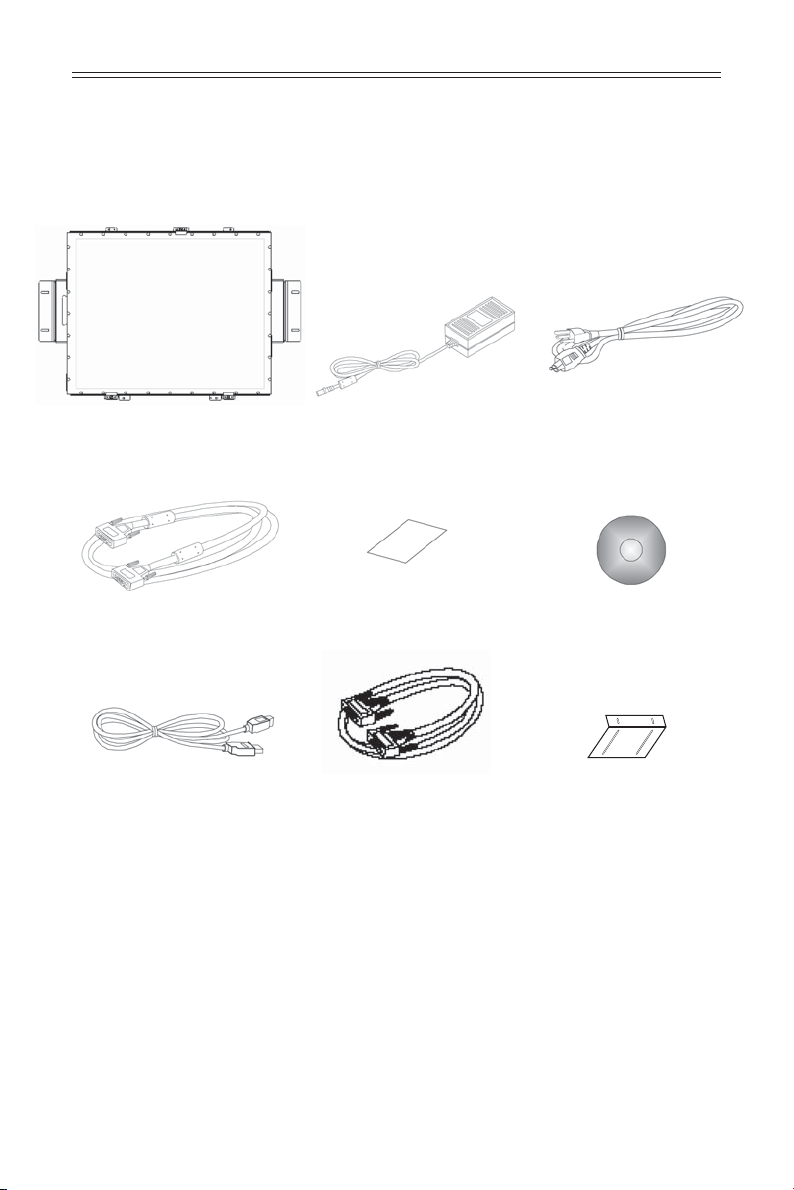
Package Overview
LCD Display
VGA Signal Cable
USB Cable
(for LA1710RTR/
LA1710RTC)
Power Adapter
Landing Strip
DVI Signal Cable
Power Cord
Touch Screen Driver
Installation CD-ROM
(for LA1710RTR/
LA1710RTC)
“L” Bracket, 2 pcs
8 LA1710R, LA1710RTR and LA1710RTC User’s Guide (020-0320-02 Rev. A)
Page 9
Installation
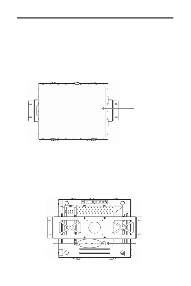
Product Overview
• Front View
• Rear View
LCD Display
Connector Ports “A”
LA1710R, LA1710RTR and LA1710RTC User’s Guide (020-0320-02 Rev. A) 9
Connector Ports “B”
Page 10

• Connector Ports “A”
• Connector Ports “B”
NOTE: Audio connector
has been removed in later
production versions.
(For LA1710RTR/LA1710RTC)
USB
10 LA1710R, LA1710RTR and LA1710RTC User’s Guide (020-0320-02 Rev. A)
Page 11

Connecting the display (Figure 1.1)
To set up this display, please refer to the following gure and
procedures.
1. Be sure all equipment is o .
2. Connect the DC power cord to the power connector. Plug one end of the
AC power cord into the power adapter, and the other end into an electrical
outlet(1).
3. For the PC with Analog graphics output: connect the VGA signal cable from
display VGA input connector to the 15-pin connector of your host computer
and tighten the screws(2).
4. For DVI-D output: connect DVI cable from display to the PC(2a).
5. For the LA1710RTR or the LA1710RTC touch screen models con gure the
touch screen. Refer to the “Touch Screen Driver Installation” section on
page 25.
6. Turn on your computer, display and video source.
Notice: To ensure the LCD display works well with your computer, con gure
the display mode of your graphic card, less than or equal to 1280
x 1024 resolution and make sure the timing of the display mode is
compatible with the LCD panel. “Video Modes” of this LCD panel are
listed in the appendices for your reference.
LA1710R, LA1710RTR and LA1710RTC User’s Guide (020-0320-02 Rev. A) 11
Page 12

Figure 1.1
12 LA1710R, LA1710RTR and LA1710RTC User’s Guide (020-0320-02 Rev. A)
Page 13

User Controls
Front Panel Controls
Menu button
Select / Auto Select- To select the adjustment items
Brightness Minus
/ Minus
Brightness Plus /
Plus
Power Switch
Power LED 1. Green indicates the display is
Displays the OSD menus.
from OSD menus.
Auto- To activate the “Auto Adjustment”
function to obtain an optimum image.
1. Decreases the brightness of the
display image.
2. Decreases value of the adjustment
items.
1. Increases the brightness of the
display image.
2. Increases value of the adjustment
items.
Switches on/o the power of the LCD
display.
turned on.
2. Amber indicates the display is in
power-saving mode.
LA1710R, LA1710RTR and LA1710RTC User’s Guide (020-0320-02 Rev. A) 13
Page 14

How to Use the OSD Menus
1. Press the “Menu” button to pop up the on-screen menu and to select
between the four main menus.
2. Choose the adjustment items by pressing the “Select/Auto” button.
3. Adjust the value of the adjustment items by pressing the “ ” button.
4. The OSD menu will automatically close, if you have left it idle for a pre-set
amount of time.
14 LA1710R, LA1710RTR and LA1710RTC User’s Guide (020-0320-02 Rev. A)
Page 15

On-Screen Display Menus
First OSD Menu:
◆ Auto-Adjustment
Choose this function to obtain an optimum image.
◆ Contrast
This function allows the user to adjust the image crispness.
Contrast adjusts the di erence between white and black shades.
◆ Horizontal Position
Changes the horizontal position of the image.
◆ Vertical Position
Changes the vertical position of the image.
◆ Clock
Changes the display data frequency to match the frequency of the
graphic card. When you are experiencing vertical ickering bar, use this
function to make an adjustment.
◆ Phase
Synchronizes the signal timing of the display to that of the graphic card.
When you are experiencing unstable to ickering image, use this
function to make an adjustment.
LA1710R, LA1710RTR and LA1710RTC User’s Guide (020-0320-02 Rev. A) 15
Page 16

On-Screen Display Menus
Second OSD Menu:
◆ Display Mode
Select this function to view the display resolution, vertical refresh, and
horizontal scan of the current mode.
◆ OSD O -Time
Adjusts the time it takes for the OSD menu to disappear.
◆ Language
Choose the language you need.
◆ Sharpness
Adjust the sharpness of the image.
◆ Reset
Returns the display parameters of the current mode to the factory
default settings.
16 LA1710R, LA1710RTR and LA1710RTC User’s Guide (020-0320-02 Rev. A)
Page 17

On-Screen Display Menus
Third OSD Menu:
◆ Volume
Controls the sound volume.
NOTE: Audio functions disabled at factory.
◆ Mute
Disables the sound immediately.
◆ Input Select
Choose the input signal.
LA1710R, LA1710RTR and LA1710RTC User’s Guide (020-0320-02 Rev. A) 17
Page 18

On-Screen Display Menus
Fourth OSD Menu:
◆ Color
Adjusts the color temperature.
◆ Color Adjustment-Red
Adjusts the red color of the display.
◆ Color Adjustment-Green
Adjusts the green color of the display.
◆ Color Adjustment-Blue
Adjusts the blue color of the display.
18 LA1710R, LA1710RTR and LA1710RTC User’s Guide (020-0320-02 Rev. A)
Page 19

Appendix
Troubleshooting
If you are experiencing trouble with the LCD display, refer to the following. If
the problem persists, please contact your local dealer or visit Planar Support
at www.planar.com/support. See support contact information on rear cover.
Problem: No image appears on screen.
◆ Check that all the I/O and power connectors are installed correctly and
well connected as described in the “Installation” section.
◆ Make sure the pins of the connectors are not crooked or broken.
◆ Recon gure the resolution of your computer to make it less than or
equal to 1280 x 1024.
Problem: Partial image or incorrectly displayed image.
◆ Check to see if the resolution of your computer is higher than that of the
LCD display.
◆ Recon gure the resolution of your computer to make it less than or
equal to 1280 x 1024.
Problem: Image has ickering vertical line bars.
◆ Use “Clock” to make an adjustment.
◆ Check and recon gure the display mode of the vertical refresh rate of
your graphic card to make it compatible with the LCD display.
Problem: Image is unstable and ickering
◆ Use “Phase” to make an adjustment.
Problem: Image is scrolling
◆ Check and make sure the VGA signal cable (or adapter) is well
connected.
◆ Check and recon gure the display mode of the vertical refresh rate of
your graphic card to make it compatible with the LCD display.
Problem: Ghosting image (characters and graphics)
◆ Use “Clock” to make an adjustment. If the problem persists,
use “Phase” to make an adjustment.
LA1710R, LA1710RTR and LA1710RTC User’s Guide (020-0320-02 Rev. A) 19
Page 20

Warning Signal
If you see warning messages on your LCD screen, this means that the LCD
display cannot receive a clean signal from the computer graphics card.
There may be three sources for this problem. Please check the cable
connections or contact Planar for more information.
◆ No Signal
This message means that the LCD display has been powered on but
it cannot receive any signal from the computer graphic card. Check all
the power switches, power cables, and VGA signal cable.
◆ Going to Sleep
This message means that the LCD display is under the power saving
mode. In addition, the LCD display will enter the sleeping mode when
experiencing a sudden signal disconnecting problem.
◆ Out of Range
This message means that the signal of the computer graphic card is not
compatible with the LCD display. When the signal is not included in the
“Video Modes” list we have listed in the Appendices of this manual, the
LCD display will display this message.
20 LA1710R, LA1710RTR and LA1710RTC User’s Guide (020-0320-02 Rev. A)
Page 21

Product Dimensions
LA1710R and LA1710RTR - Front View:
LA1710R/RTR Front View
LA1710R, LA1710RTR and LA1710RTC User’s Guide (020-0320-02 Rev. A) 21
Page 22

LA1710R and LA1710RTR - Side View:
LA1710R (non touch)
LA1710RTR (capacitive touch)
LA1710RTR (resistive touch)
22 LA1710R, LA1710RTR and LA1710RTC User’s Guide (020-0320-02 Rev. A)
Page 23

LA1710R and LA1710RTR - Rear View:
LA1710R/RTR Rear View
LA1710R, LA1710RTR and LA1710RTC User’s Guide (020-0320-02 Rev. A) 23
Page 24

Video Modes
The monitor supports the following industry-standard combinations of
screen resolution and refresh rates. Other combinations are possible, but
may require adjustments to the image.
For the optimal performance, set your computer to a screen resolution of
1024 x 768 at a 60 Hz refresh rate.
24 LA1710R, LA1710RTR and LA1710RTC User’s Guide (020-0320-02 Rev. A)
Page 25

Touch Screen Driver Installation
Driver Installation for LA1710RTR:
Resistive Touch Screen with USB Connection
Please note: These monitors are Microsoft Windows® HID (Human Interface
Device) compatible. No additional software driver is required for general operation of the touch screen.
A special calibration tool can be installed for improved touch position accuracy. See Optional MicroTouchTM USB HID Calibration Tool version 7.00
Installation Process.
Optional Driver MicroTouchTM USB HID Calibration Tool Version
7.00 Installation Process for LA1710RTR: Resistive Touch Screen
with USB Connection
Please note: These monitors are Microsoft HID (Human Interface Device)
compatible. The calibration driver is not required for general operation of the
touch screen.
This calibration tool is for optimization of touch performance for the touch
screen to meet the 1% TPE accuracy speci cation.
The following Microsoft Windows® operating systems are supported by this
software driver: Microsoft Windows® XP, Vista, and Windows® 7.
1. Be sure that the USB cable is not connected to the PC.
2. Open the CD-Rom.
3. Click the “LA1500RTR, LA1710RTR, PT1500MU / 1700MU Calibration
Option” link.
4. Click “I accept” when the software license screen appears.
5. Follow the step-by-step instructions.
6. Reconnect the USB cable to the computer prior to use.
7. If the touch screen driver does not automatically load, restart the computer
operating system.
Please read “Readme.txt” located in the unzipped le folder for
additional information and assistance.
LA1710R, LA1710RTR and LA1710RTC User’s Guide (020-0320-02 Rev. A) 25
Page 26

Driver Installation for LA1710RTC: Capacitive Touch screen with USB
Connection
Touch driver information is located on the enclosed CD-ROM for the following
operating systems: Microsoft Windows® XP, Windows® Vista, and Windows® 7.
1. Be sure that the USB cable is not connected to the PC.
2. Open the CD-Rom.
3. Click the “LA1710RTC, Win XP, Vista, Win 7” link
4. Click “I accept” when the software license screen appears.
5. Follow the step-by-step instructions.
6. Reconnect the USB cable to the computer prior to use.
7. If the touch screen driver does not automatically load, restart the computer
operating system.
Please read “Readme.txt” located in the unzipped le folder for additional
information and assistance.
26 LA1710R, LA1710RTR and LA1710RTC User’s Guide (020-0320-02 Rev. A)
Page 27

Linux Driver Installation for LA1710RTC: Capacitive Touch screen
with USB Connection
Touch driver information is located on the enclosed CD-ROM. Supported platforms include: Red Hat® Linux 8.0, Red Hat® Linux 9.0, and SuSE® Linux 8.2
and SuSE® Linux 9.0 on Pentium®-compatible CPUs. The following Xfree86
versions are supported: 4.0.3 and 4.1.0.
1. Open the CD-Rom.
2. Click the “LA1500RTR, LA1710RTR, LA1710RTC, Linux” link
3. Click “I accept” when the software license screen appears.
4. Follow the step-by-step instructions.
5. If the touch screen driver does not automatically load, restart the computer
operating system.
Please read “Readme.txt” located in the unzipped le folder for additional
information and assistance.
LA1710R, LA1710RTR and LA1710RTC User’s Guide (020-0320-02 Rev. A) 27
Page 28

Support and Service
Planar is a US company based in Beaverton, Oregon and Espoo, Finland with
a worldwide sales distribution network.
Visit Planar at http://www.planar.com/support for product registration,
operations manuals, line drawings, touch screen drivers, warranty information
and access to Planar’s Technical Library for online troubleshooting.
To speak with Planar Customer Support please have your model and serial number
available and dial one of these numbers:
Americas Support
Tel: 1-866-PLANAR1 (866-752-6271) or +1 503-748-1100
Hours: M-F, 8am - 8pm Eastern Time | M-F, 5am - 5pm Paci c Time
Europe and Asia-Paci c Support
Tel: +358-9-420-01
Hours: M-F, 7:00am - 4pm CET
Toll or long distance charges may apply.
28 LA1710R, LA1710RTR and LA1710RTC User’s Guide (020-0320-02 Rev. A)
Page 29

Planar Systems, Inc.
Customer Service
24x7 Online Technical Support: http://www.planar.com/support
Americas Support
Tel: 1-866-PLANAR1 (866-752-6271) or +1 503-748-1100
Hours: M-F, 8am - 8pm Eastern Time | M-F, 5am - 5pm Paci c Time
Europe and Asia-Paci c Support
Tel: +358-9-420-01
Hours: M-F, 7:00am - 4pm CET
© 2010 Planar Systems, Inc. 05/08 Planar is a registered trademark of Planar Systems, Inc.
Other brands and names are the property of their respective owners.
Technical information in this document is subject to change without notice.
Document No.
020-0320-02 Rev. A
 Loading...