

Page 1
Page 2

The information contained in this document is subject to change without notice.
This document contains proprietary information that is protected by copyright. All
rights are reserved. No part of this document may be reproduced, translated to
another language or stored in a retrieval system, or transmitted by any means,
electronic, mechanical, photocopying, recording, or otherwise, without prior written
permission.
Windows is a registered trademark of Microsoft, Inc.
Other brand or product names are trademarks of their respective holders.
Page 3

TT
able of Contentsable of Contents
T
able of Contents
TT
able of Contentsable of Contents
Usage Notice
Precautions . . . . . . . . . . . . . . . . . . . . . . . . . . . . . . . . . . . . . . . . . . . . . . . . . . . . . . . . . . . . . . . . 1
Introduction
About the Product . . . . . . . . . . . . . . . . . . . . . . . . . . . . . . . . . . . . . . . . . . . . . . . . . . . . . . . . . 2
Package Overview . . . . . . . . . . . . . . . . . . . . . . . . . . . . . . . . . . . . . . . . . . . . . . . . . . . . . . . . . 5
Installation
Product Overview . . . . . . . . . . . . . . . . . . . . . . . . . . . . . . . . . . . . . . . . . . . . . . . . . . . . . . . . . . 6
User Controls
Front Panel Controls . . . . . . . . . . . . . . . . . . . . . . . . . . . . . . . . . . . . . . . . . . . . . . . . . . . . . . 10
How to Use the OSD Menus . . . . . . . . . . . . . . . . . . . . . . . . . . . . . . . . . . . . . . . . . . . . . . 11
On-Screen Display Menus . . . . . . . . . . . . . . . . . . . . . . . . . . . . . . . . . . . . . . . . . . . . . . . . 12
Appendix
Troubleshooting. . . . . . . . . . . . . . . . . . . . . . . . . . . . . . . . . . . . . . . . . . . . . . . . . . . . . . . . . . 16
Warning Signal . . . . . . . . . . . . . . . . . . . . . . . . . . . . . . . . . . . . . . . . . . . . . . . . . . . . . . . . . . . 17
Product Dimensions. . . . . . . . . . . . . . . . . . . . . . . . . . . . . . . . . . . . . . . . . . . . . . . . . . . . . . 18
Video Modes. . . . . . . . . . . . . . . . . . . . . . . . . . . . . . . . . . . . . . . . . . . . . . . . . . . . . . . . . . . . . 19
Touch Screen Driver Installation . . . . . . . . . . . . . . . . . . . . . . . . . . . . . . . . . . . . . . . . . . . 20
Page 4

Usage NoticeUsage Notice
Usage Notice
Usage NoticeUsage Notice
!
WW
ARNINGARNING
W
ARNING
WW
Ì
Ì
Safety and Use PrecautionsSafety and Use Precautions
Safety and Use Precautions
Safety and Use PrecautionsSafety and Use Precautions
Follow all warnings, precautions and maintenance as recommended in this User’s
Guide to maximize the life of your unit.
Do:Do:
Do:
Do:Do:
ARNINGARNING
!
WW
ARNING –ARNING –
W
ARNING –
WW
ARNING –ARNING –
Turn off the product before cleaning.
Use only a dry soft cloth or clean room wiper when cleaning the LCD
panel surface.
Use only high quality and safety approved AC/DC power adapter.
Disconnect the power plug from AC outlet if the product is not used for
a long period of time.
– –
TT
o pro pr
evev
enen
t the rt the r
–
T
o pr
ev
o pro pr
evev
en
enen
TT
– –
expose this product to rain or moisture.expose this product to rain or moisture.
expose this product to rain or moisture.
expose this product to rain or moisture.expose this product to rain or moisture.
Please do not open or disassemble the product as thisPlease do not open or disassemble the product as this
Please do not open or disassemble the product as this
Please do not open or disassemble the product as thisPlease do not open or disassemble the product as this
may cause electric shock.may cause electric shock.
may cause electric shock.
may cause electric shock.may cause electric shock.
t the r
t the rt the r
isk of firisk of fir
isk of fir
isk of firisk of fir
e or shock hazare or shock hazar
e or shock hazar
e or shock hazare or shock hazar
dsds
, do not, do not
ds
, do not
dsds
, do not, do not
Don’t:Don’t:
Don’t:
Don’t:Don’t:
Do not touch the LCD panel surface with sharp or hard objects.
Do not use abrasive cleaners, waxes or solvents for cleaning.
Do not operate the product under the following conditions:
- Extremely hot, cold or humid environment.
- Areas susceptible to excessive dust and dirt.
- Near any appliance generating a strong magnetic field.
- Place in direct sunlight.
1
Page 5

IntroductionIntroduction
Introduction
IntroductionIntroduction
About Planar's LA1710RTR, LA1710RTCAbout Planar's LA1710RTR, LA1710RTC
About Planar's LA1710RTR, LA1710RTC
About Planar's LA1710RTR, LA1710RTCAbout Planar's LA1710RTR, LA1710RTC
The LA17 products all have a 17" flat panel screen with an active matrix, thin-film
transistor (TFT) liquid crystal display (LCD).
Features include:Features include:
Features include:
Features include:Features include:
Dual signal input: Analog VGA and Digital DVI-D
Active matrix TFT LCD technology
1280 x 1024 SXGA resolution
17" viewable display area
31.5 ~ 80 kHz horizontal scan
56 ~ 75 Hz refresh rate
0.264mm x 0.264mm pixel pitch
260 cd/m
450:1 (typ.) contrast ratio
L/R = 70/70, U/D = 70/70 viewing angle, CR=10
Tr = 12 ms (typ.)/Tf = 4 ms (typ.) response time
4CCFLs backlights lamps w/50,000 hrs life
Auto-adjustment function
Multilingual OSD user controls
VESA DPMS power saving
Durable touchscreen
2
(typ.) brightness
2
Page 6

TT
ouch Screen fouch Screen f
T
ouch Screen f
TT
ouch Screen fouch Screen f
Resistive for finger and pen interfaceResistive for finger and pen interface
Resistive for finger and pen interface
Resistive for finger and pen interfaceResistive for finger and pen interface
Surface: Anti-glare treatment
Interface: USB
Durability: 1,000,000 activations at a single point
Hardness: 4H per ASTM D3363-92
Operating force: Stylus - <25 g (average)
Transmissirity: 85% + / - 2% (typical)
Haze: 5%
Clarity: 80%
Driver: Windows 95/98/Me/NT/2000/XP
Linux
or LA1710RTRor LA1710RTR
or LA1710RTR
or LA1710RTRor LA1710RTR
Finger - <50 g (average)
3
Page 7

TT
ouch Screen fouch Screen f
T
ouch Screen f
TT
ouch Screen fouch Screen f
Capacitive for finger interfaceCapacitive for finger interface
Capacitive for finger interface
Capacitive for finger interfaceCapacitive for finger interface
Surface: Anti-glare treatment
Interface: USB
Durability: 225,000,000 touches in a single location
Hardness: Cannot be scratched using any stylus with Mohs' rating of less
Transmissivity: up to 88% at 550 nm
or LA1710RTCor LA1710RTC
or LA1710RTC
or LA1710RTCor LA1710RTC
than 6.5
Driver: Windows®
Linux
MS HID compatible pointing device
95/98/Me/NT/2000/XP,
4
Page 8
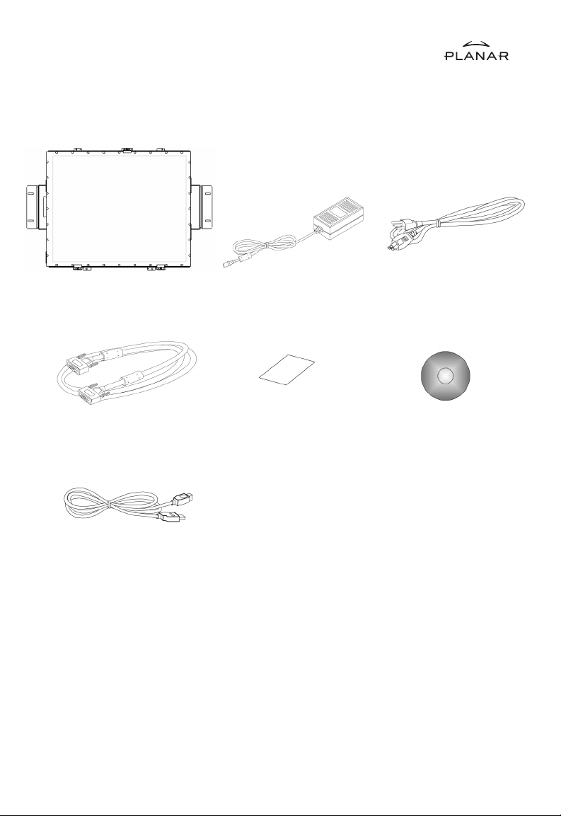
Package OverviewPackage Overview
Package Overview
Package OverviewPackage Overview
LCD Display
VGA Signal Cable
USB Cable
Power Adapter
Landing Strip
Power Cord
Touch Screen Driver
Installation CD-ROM
5
Page 9

InstInst
allationallation
Inst
allation
InstInst
allationallation
Product OverviewProduct Overview
Product Overview
Product OverviewProduct Overview
• Front View• Front View
• Front View
• Front View• Front View
• Rear View• Rear View
• Rear View
• Rear View• Rear View
LCD Display
Connector Ports “A”
Connector Ports “B”
6
Page 10

• Connector Ports “A”• Connector Ports “A”
• Connector Ports “A”
• Connector Ports “A”• Connector Ports “A”
• Connector Ports “B”• Connector Ports “B”
• Connector Ports “B”
• Connector Ports “B”• Connector Ports “B”
USB
7
Page 11

ConnConn
ecting the displayecting the display
Conn
ecting the display
ConnConn
ecting the displayecting the display
To configure this monitor, please refer to the following figure and procedures.
1. Be sure all equipment is off.
2. Connect the DC power cord to the power connector. Plug one end of the AC power
cord into the power adapter, and the other end into an electrical outlet
(1.1 1 ).
3. For the PC with Analog output: connect the VGA signal cable from display VGA
input connector to the 15-pin connector of your host computer and tighten the
screws (1.1 2 ).
4. Connect the USB cable from USB port of your display to the USB port of your
computer (1.1 3 ).
5. Turn on your computer, display and video source.
(F(F
igure 1.1)igure 1.1)
(F
igure 1.1)
(F(F
igure 1.1)igure 1.1)
Notice:Notice:
Notice: To ensure the LCD display works well with your computer, configure the
Notice:Notice:
display mode of your graphic card, less than or equal to 1280 x 1024
resolution and make sure the timing of the display mode is compatible
with the LCD panel. "Video Modes" of this LCD panel are listed in the
appendix for your reference."
8
Page 12

Figure 1.1Figure 1.1
Figure 1.1
Figure 1.1Figure 1.1
9
Page 13

User ControlsUser Controls
User Controls
User ControlsUser Controls
FF
ront Panront Pan
F
ront Pan
FF
ront Panront Pan
el Controlsel Controls
el Controls
el Controlsel Controls
Menu button Displays the OSD menus.
Select / Auto
Select-
To select the adjustment items from
OSD menus.
Auto-
To activate the “Auto Adjustment”
function to obtain an optimum image.
Brightness Minus /
Minus
Brightness Plus /
Plus
Power Switch Switches on/off the power of the LCD
Power LED 1. Green indicates the display is turned
1. Decreases the brightness of the
display image.
2. Decreases value of the adjustment
items.
1. Increases the brightness of the display
image.
2. Increases value of the adjustment
items.
display.
on.
2. Amber indicates the display is in
power-saving mode.
10
Page 14

How to Use the OSD MenusHow to Use the OSD Menus
How to Use the OSD Menus
How to Use the OSD MenusHow to Use the OSD Menus
1. Press the “Menu” button to pop up the on-screen menu and to select between the
four main menus.
2. Choose the adjustment items by pressing the “Select/Auto” button.
3. Adjust the value of the adjustment items by pressing the “
4. The OSD menu will automatically close, if you have left it idle for a pre-set time.
” button.
11
Page 15

On-Screen Display MenusOn-Screen Display Menus
On-Screen Display Menus
On-Screen Display MenusOn-Screen Display Menus
First OSD Menu:
Auto-AdjustmentAuto-Adjustment
`
Auto-Adjustment
Auto-AdjustmentAuto-Adjustment
Choose this function to obtain an optimum image.
ContrastContrast
`
Contrast
ContrastContrast
This function allows the user to adjust the image crispness. Contrast adjusts the
difference between white and black shades.
Horizontal PositionHorizontal Position
`
Horizontal Position
Horizontal PositionHorizontal Position
Changes the horizontal position of the image.
Vertical PositionVertical Position
`
Vertical Position
Vertical PositionVertical Position
Changes the vertical position of the image.
BrightnessBrightness
`
Brightness
BrightnessBrightness
Adjusts the brightness of the image.
ClockClock
`
Clock
ClockClock
Changes the display data frequency to match the frequency of your graphic card.
When you are experiencing vertical flickering bar, use this function to make an
adjustment.
PhasePhase
`
Phase
PhasePhase
Synchronizes the signal timing of the display to that of the graphic card. When
you are experiencing unstable to flickering image, use this function to make an
adjustment.
12
Page 16

On-Screen Display MenusOn-Screen Display Menus
On-Screen Display Menus
On-Screen Display MenusOn-Screen Display Menus
Second OSD Menu:
Display ModeDisplay Mode
`
Display Mode
Display ModeDisplay Mode
Selects this function to view the display resolution, vertical refresh, and horizontal
scan of the current mode.
OSD OOSD O
ff-ff-
TT
`
OSD O
OSD OOSD O
Adjusts the time it takes for the OSD menu to disappear.
ff-
ff-ff-
T
TT
imeime
ime
imeime
LanguageLanguage
`
Language
LanguageLanguage
Chooses the language you need.
SharpnessSharpness
`
Sharpness
SharpnessSharpness
Adjust the sharpness of the image.
ResetReset
`
Reset
ResetReset
Returns the display parameters of the current mode to the factory default settings.
13
Page 17

On-Screen Display MenusOn-Screen Display Menus
On-Screen Display Menus
On-Screen Display MenusOn-Screen Display Menus
Third OSD Menu:
VolumeVolume
`
Volume
VolumeVolume
It allows the sound volume.
MuteMute
`
Mute
MuteMute
It allows you to disable the sound immediately.
Input SelectInput Select
`
Input Select
Input SelectInput Select
It allows you the chosse the input signal.
14
Page 18

On-Screen Display MenusOn-Screen Display Menus
On-Screen Display Menus
On-Screen Display MenusOn-Screen Display Menus
Fourth OSD Menu:
ColorColor
`
Color
ColorColor
Adjusts the color temperature.
Color Adjustment-RedColor Adjustment-Red
`
Color Adjustment-Red
Color Adjustment-RedColor Adjustment-Red
Adjusts the red color of the display.
Color Adjustment-GreenColor Adjustment-Green
`
Color Adjustment-Green
Color Adjustment-GreenColor Adjustment-Green
Adjusts the green color of the display.
Color Adjustment-BlueColor Adjustment-Blue
`
Color Adjustment-Blue
Color Adjustment-BlueColor Adjustment-Blue
Adjusts the blue color of the display.
15
Page 19

AppendixAppendix
Appendix
AppendixAppendix
TT
rourou
bleshootingbleshooting
T
rou
bleshooting
TT
rourou
bleshootingbleshooting
If you are experiencing trouble with the LCD display, refer to the following. If the
problem persists, please contact your local dealer or our service center.
Problem: No image appears on screen.Problem: No image appears on screen.
Problem: No image appears on screen.
Problem: No image appears on screen.Problem: No image appears on screen.
` Check that all the I/O and power connectors are correctly and well connected as
described in the “Installation” section.
` Make sure the pins of the connectors are not crooked or broken.
Problem: Partial image or incorrectly displayed the image.Problem: Partial image or incorrectly displayed the image.
Problem: Partial image or incorrectly displayed the image.
Problem: Partial image or incorrectly displayed the image.Problem: Partial image or incorrectly displayed the image.
` Check to see if the resolution of your computer is higher than that of the LCD
display.
` Reconfigure the resolution of your computer to make it less than or equal to
1280 x 1024.
Problem: Image has flickering vertical line bars.Problem: Image has flickering vertical line bars.
Problem: Image has flickering vertical line bars.
Problem: Image has flickering vertical line bars.Problem: Image has flickering vertical line bars.
` Use “Clock” to make an adjustment.
` Check and reconfigure the display mode of the vertical refresh rate of your graphic
card to make it compatible with the LCD display.
Problem: Image is unstable and flickeringProblem: Image is unstable and flickering
Problem: Image is unstable and flickering
Problem: Image is unstable and flickeringProblem: Image is unstable and flickering
` Use “Phase” to make an adjustment.
Problem: Image is scrollingProblem: Image is scrolling
Problem: Image is scrolling
Problem: Image is scrollingProblem: Image is scrolling
` Check and make sure the VGA signal cable (or adapter) is well connected.
` Check and reconfigure the display mode of the vertical refresh rate of your graphic
card to make it compatible with the LCD display.
Problem: Vague image (characters and graphics)Problem: Vague image (characters and graphics)
Problem: Vague image (characters and graphics)
Problem: Vague image (characters and graphics)Problem: Vague image (characters and graphics)
` Use “Clock” to make an adjustment. If this problem still exists, use “Phase” to make
an adjustment.
16
Page 20

Warning SignalWarning Signal
Warning Signal
Warning SignalWarning Signal
If you see warning messages on your LCD screen, this means that the LCD display
cannot receive a clean signal from the computer graphics card.
There may be two sources for this problem. Please check the cable connections or
contact Planar for more information.
No SignalNo Signal
`
No Signal
No SignalNo Signal
This message means that the LCD display has been powered on but it cannot
receive any signal from the computer graphic card. Check all the power switches,
power cables, and VGA signal cable.
Out of RangeOut of Range
`
Out of Range
Out of RangeOut of Range
This message means that the signal of the computer graphic card is not
compatible with the LCD display. When the signal is not included in the “Video
Modes” list we have listed in the Appendices of this manual, the LCD display will
display this message.
17
Page 21

Product DimensionsProduct Dimensions
Product Dimensions
Product DimensionsProduct Dimensions
18
Page 22

VV
ideo Modesideo Modes
V
ideo Modes
VV
ideo Modesideo Modes
The monitor supports the following industry-standard combinations of screen
resolution and refresh rates. Other combinations are possible, but may require
adjustments to the image.
For the optimal performance, set your computer to a screen resolution of 1024 x 768
at a 60 Hz refresh rate.
19
Page 23

TT
ouch Screen Drivouch Screen Driv
T
ouch Screen Driv
TT
ouch Screen Drivouch Screen Driv
DrivDriv
er Inster Inst
Driv
er Inst
DrivDriv
er Inster Inst
USB ConnectionUSB Connection
USB Connection
USB ConnectionUSB Connection
Please note: These monitors are Microsoft Windows® HID( Human Interface Device)
compatible. No additional software driver is required for general operation of the
touch screen.
A special calibration tool can be installed for improved touch position accuracy. See
Optional MicroTouchTM USB HID Calibration Tool version 7.00 Installation Process.
allation fallation f
allation f
allation fallation f
er Inster Inst
er Inst
er Inster Inst
or LA1710RTR:or LA1710RTR:
or LA1710RTR:
or LA1710RTR:or LA1710RTR:
allationallation
allation
allationallation
Resistiv Resistiv
Resistiv
Resistiv Resistiv
e e
TT
ouch Screen withouch Screen with
e
T
ouch Screen with
e e
TT
ouch Screen withouch Screen with
OptionOption
Option
OptionOption
7.00 Inst7.00 Inst
7.00 Inst
7.00 Inst7.00 Inst
with USB Connectionwith USB Connection
with USB Connection
with USB Connectionwith USB Connection
Please note: These monitors are Microsoft HID (Human Interface Device) compatible.
The calibration driver is not required for general operation of the touch screen.
This calibration tool is for optimization of touch performance for the touch screen to
meet the 1% TPE accuracy specification.
The following Microsoft Windows® operating systems are supported by this software
driver:
1. Open the CD-Rom.
2. Select the PT1500MU Calibration Option link.
3. The driver file will automatically open.
4. Follow the installation instructions for the MicroTouch HID Calibration
Please read “Readme.txt” located in the unzipped file folder for additionalPlease read “Readme.txt” located in the unzipped file folder for additional
Please read “Readme.txt” located in the unzipped file folder for additional
Please read “Readme.txt” located in the unzipped file folder for additionalPlease read “Readme.txt” located in the unzipped file folder for additional
information and assistance.information and assistance.
information and assistance.
information and assistance.information and assistance.
al Drival Driv
al Driv
al Drival Driv
Microsoft Windows® 98SE, Me, 2000, and XPMicrosoft Windows® 98SE, Me, 2000, and XP
Microsoft Windows® 98SE, Me, 2000, and XP
Microsoft Windows® 98SE, Me, 2000, and XPMicrosoft Windows® 98SE, Me, 2000, and XP
procedure.
er MicroTer MicroT
er MicroT
er MicroTer MicroT
allation Process fallation Process f
allation Process f
allation Process fallation Process f
ouch™ USB HID Calibration ouch™ USB HID Calibration
ouch™ USB HID Calibration
ouch™ USB HID Calibration ouch™ USB HID Calibration
or LA1710RTR:or LA1710RTR:
or LA1710RTR:
or LA1710RTR:or LA1710RTR:
Resistiv Resistiv
Resistiv
Resistiv Resistiv
.
TT
ool ool
VV
T
ool
V
TT
ool ool
VV
e e
TT
ouch Screenouch Screen
e
T
ouch Screen
e e
TT
ouch Screenouch Screen
ersionersion
ersion
ersionersion
20
Page 24

DrivDriv
er Inster Inst
Driv
er Inst
DrivDriv
er Inster Inst
USB ConnectionUSB Connection
USB Connection
USB ConnectionUSB Connection
Touch driver information is located on the enclosed CD-ROM for the following
operating systems:
Windows Me, and Windows 9XWindows Me, and Windows 9X
Windows Me, and Windows 9X
Windows Me, and Windows 9XWindows Me, and Windows 9X
If you have a USB cable connection disconnect the cable from the monitor or the PC
before installing the driver.
1. Open the CD-Rom.
2. Select the link for your monitor model.
3. The driver will automatically open.
4. Select the “TW564SR4.exe file.
5. Select “unzip”
6. Double click the “setup.exe” file.
7. Follow the installation instructions.
8. Reconnect the USB cable
9. If the touch screen driver does not automatically load, restart the computer
operating system.
Please read “Readme.txt” located in the unzipped file folder for additionalPlease read “Readme.txt” located in the unzipped file folder for additional
Please read “Readme.txt” located in the unzipped file folder for additional
Please read “Readme.txt” located in the unzipped file folder for additionalPlease read “Readme.txt” located in the unzipped file folder for additional
information and assistance.information and assistance.
information and assistance.
information and assistance.information and assistance.
allation fallation f
allation f
allation fallation f
or LA1710RTC:or LA1710RTC:
or LA1710RTC:
or LA1710RTC:or LA1710RTC:
Microsoft Windows® XP, Windows 2000, Windows NT 4.0, Microsoft Windows® XP, Windows 2000, Windows NT 4.0,
Microsoft Windows® XP, Windows 2000, Windows NT 4.0,
Microsoft Windows® XP, Windows 2000, Windows NT 4.0, Microsoft Windows® XP, Windows 2000, Windows NT 4.0,
.
Capacitiv Capacitiv
Capacitiv
Capacitiv Capacitiv
e e
TT
ouch Screen withouch Screen with
e
T
ouch Screen with
e e
TT
ouch Screen withouch Screen with
21
Page 25

Linux DrivLinux Driv
Linux Driv
Linux DrivLinux Driv
with USB Connectionwith USB Connection
with USB Connection
with USB Connectionwith USB Connection
Touch driver information is located on the enclosed CD-ROM. Supported platforms
include:
9.0 on Pentium®-compatible CPUs. The following Xfree86 versions are supported: 4.9.0 on Pentium®-compatible CPUs. The following Xfree86 versions are supported: 4.
9.0 on Pentium®-compatible CPUs. The following Xfree86 versions are supported: 4.
9.0 on Pentium®-compatible CPUs. The following Xfree86 versions are supported: 4.9.0 on Pentium®-compatible CPUs. The following Xfree86 versions are supported: 4.
0.3 and 4.1.00.3 and 4.1.0
0.3 and 4.1.0
0.3 and 4.1.00.3 and 4.1.0
1. Open the CD-Rom.
2. Select the “TwLinux5.62.1” folder.
3. Double click the “Readme.txt” file.
4. Follow the driver selection and installation instructions.
Please read “Readme.txt” located in the unzipped file folder for additionalPlease read “Readme.txt” located in the unzipped file folder for additional
Please read “Readme.txt” located in the unzipped file folder for additional
Please read “Readme.txt” located in the unzipped file folder for additionalPlease read “Readme.txt” located in the unzipped file folder for additional
information and assistance.information and assistance.
information and assistance.
information and assistance.information and assistance.
er Inster Inst
er Inst
er Inster Inst
Red Hat® Linux 8.0, Red Hat® Linux 9.0, and SuSE® Linux 8.2 and SuSE® LinuxRed Hat® Linux 8.0, Red Hat® Linux 9.0, and SuSE® Linux 8.2 and SuSE® Linux
Red Hat® Linux 8.0, Red Hat® Linux 9.0, and SuSE® Linux 8.2 and SuSE® Linux
Red Hat® Linux 8.0, Red Hat® Linux 9.0, and SuSE® Linux 8.2 and SuSE® LinuxRed Hat® Linux 8.0, Red Hat® Linux 9.0, and SuSE® Linux 8.2 and SuSE® Linux
.
allation fallation f
allation f
allation fallation f
or LA1710RTC:or LA1710RTC:
or LA1710RTC:
or LA1710RTC:or LA1710RTC:
Capacitiv Capacitiv
Capacitiv
Capacitiv Capacitiv
e e
TT
ouch Screenouch Screen
e
T
ouch Screen
e e
TT
ouch Screenouch Screen
22
Page 26

Planar Systems, Inc.
Customer Service
Online Support: http://planar.custhelp.com
Email: desktopmonitors@planar.com
Tel: 1-866-PLANAR-1 (1-866-752-6271)
Hours: m-f, 8am-9pm, Eastern Time
© 2004 Planar Systems, Inc. Planar is a registered trademark of Planar Systems, Inc.
Other brands and names are the property of their respective owners.
Technical information in this document is subject to change without notice.
12/04
Document No. : 020-0320-00 Rev.B
 Loading...