

Page 1
GX3MP Display
Reference Guide
Windows XP
Windows 2000
Page 2
Important recycle instruction
Lamp(s) inside this product contain mercury. This product may
contain other electronic waste that can be hazardous if not disposed
of properly. Recycle or dispose in accordance with local, state, or
federal laws. For more information, contact the Electronic Industries
Alliance at WWW.EIAE.ORG. For lamp-speci c disposal information,
check WWW.LAMPRECYCLE.ORG.
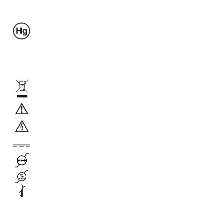
Symbol explanations
Disposal. Do not use household or municipal waste collection
services for disposal of electrical and electronic equipment.
EU countries require the use of separate recycling collection services.
Caution. Read the accompanying text carefully, for proper operation
and maintenance of the display system.
Dangerous Voltage. Important precautions about electric shock.
Read the accompanying text carefully, to prevent damage to
components of the display system and for your safety.
Direct Current.
Barometric Pressure. Transport and storage 12,000 meters
(39,400 feet), maximum in unpressurized container
Relative Humidity. Transport and storage 5% to 90%
(non-condensing).
Temperature. Transport and storage -10° to 60° C.
2
Page 3
Before You Begin
The 21-inch Planar GX3MP grayscale display provides resolutions of
1536 x 2048 pixels in portrait mode and 2048 x 1536 pixels in landscape mode.
Check that your system meets these requirements for installation of
the Planar GX3MP display system.
System Requirements Operating System
• Intel Pentium 4/Xeon, AMD Athlon 64/K7/XP,
or compatible
• PCI Express x16 lane slot
• 50 MB hard disk space
• 256 MB RAM
• CD-ROM drive
• Power supply, 350 watts or greater
Windows XP Service Pack 2 or
Windows 2000 Service Pack 4
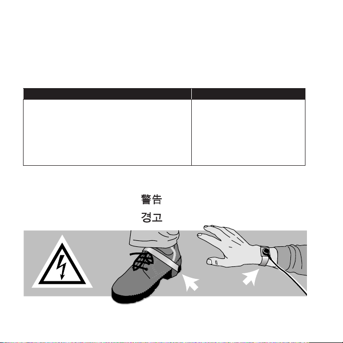
Safety Precaution
Warning
Avertissement
Avvertenza
Advertencia
Warnung
Wear an antistatic heel or
wrist strap when installing the
video card to avoid damage to
computer components.
3
Page 4
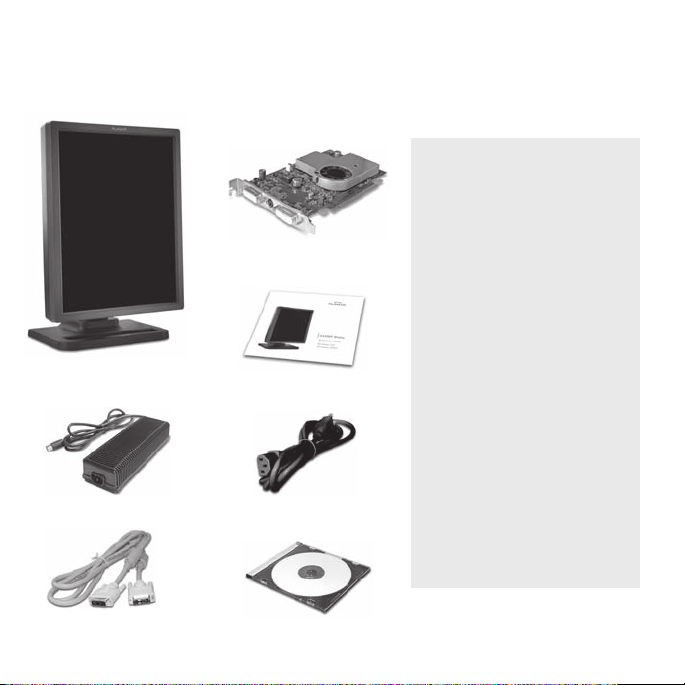
Unpacking the Display
Check the contents of your Planar GX3MP display package for all the items
shown here. Save the original packaging materials for storage and shipping.
Guidelines
• Use both hands to lift
or adjust the display.
• Avoid touching the
display screen.
• Do not set up the display
in areas with sudden
temperature changes and
strong light sources.
• Do not block the vents on
the back of the display.
• Do not remove the back
cover or disassemble
the display.
• In locations where 240V
outlets are used, connect
the display only to a
center-tapped, 240V,
single-phase supply.
Planar GX3MP
digital at panel
Power block
Graphics card
Reference guide
Power cord
DVI-to-DVI video cable
4
Display driver
Page 5
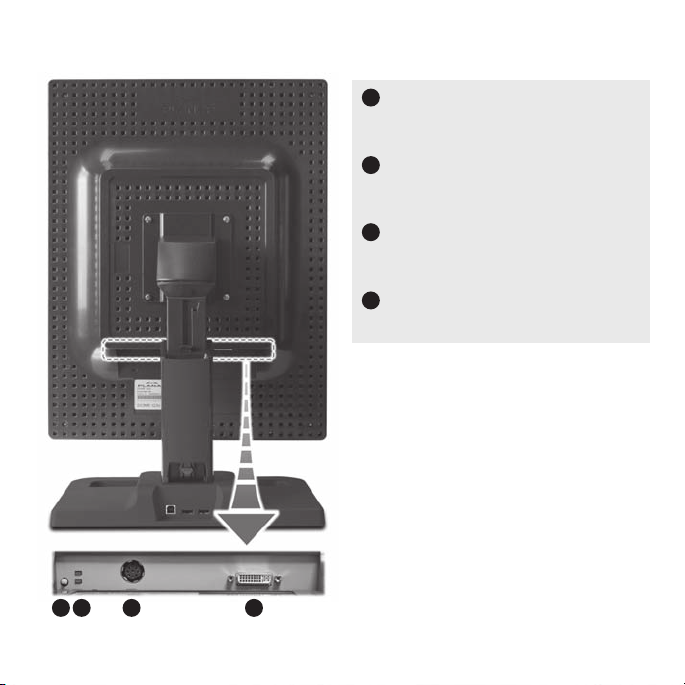
Display Components
1 2 3 4
Reset button.
1
Restores the display con guration
to its default setting.
LED status lights.
2
Provides information about the
status of the display.
3
DIN connector.
Drives power to the display via
an 8-pin connector.
DVI connector.
4
Drives the data to the display.
See page 12 for information on
adjusting the display position.
5
Page 6
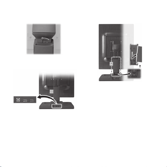
Desk Stand Features
Stand lock
Move the stand lock lever to the left to
unlock the column extension.
USB hub
Use the integrated, bus-powered USB hub
on the stand to attach USB devices to the
display You must connect the display to
a USB-compliant computer or to another
hub with a USB cable. Even if the display
is in power-saving mode, the USB devices
function when connected to the USB
ports of the stand.
Stand cable cover
Press the PUSH button at the
bottom of the stand and pull
the cable cover down and out
to remove it.
Thread the power cord and DVI
cable through the stand column.
Make sure the cord and cable run
through the notches.
To reattach the cable cover, align
the hooks with the slots on the
stand. Press the cover into place.
A click sound signals a secure
connection.
6
Page 7

Installing the Graphics Card
If you leave the computer turned on, you could get an electric shock
and cause damage to the system components.
Remove the graphics card slowly from its package and static-shielding
bag to prevent an electrostatic discharge.
Static electricity can damage the card. When touching the card or parts of
the motherboard, take these precautions:
• Wear an antistatic wrist strap.
• Discharge your body’s static electricity repeatedly by touching the power
supply or the metal surface of the computer chassis.
To install the controller
1 Turn o all peripherals. Disconnect all cables from the back of
your computer.
2 Remove the computer cover.
3 Remove the blank bracket from the PCI Express slot.
4 Insert the graphics card into the slot, align the connector pins,
and press the board down until it is rmly seated.
5 Secure the mounting bracket.
6 Reattach the computer cover and the peripherals.
When installing multiple graphics cards, install all cards before you
install the driver.
7
Page 8

Making the Connections
Use only the DVI cable and power cord supplied with your Planar GX3MP display.
To connect the display
1 Plug one end of the DVI cable
into the DVI connector port.
Tighten the thumbscrews to
secure the connection.
2 Plug the power cord into
the power input port.
3 Plug the other end of the
DVI cable into DVI port 1
(the bottom port) on the
installed graphics card.
4 Plug the other end of
the power cord into a
grounded outlet.
5 Power on your display
rst, then the computer.
Power cord DVI cable
8
Page 9

Use DVI port 1 (the bottom port) to connect a single display to the graphics card
or to install the primary display of a dual con guration.
DVI cable
DVI
port 1
AX3 graphics
card installed
9
Page 10

Installing the Display Driver
Before you install the driver, remove any previously installed display driver for
the graphics card from your system.
To install the driver
1 Start the system. Click Cancel on the Found New Hardware Wizard dialog.
Click No when the system prompts you to restart the computer.
2 Insert the driver installation CD and run Setup.exe .
3 Click Next.
4 Click Ye s to the license agreement. The installation starts.
5 Follow the onscreen instructions to complete the installation.
Planar recommends that you select the Express installation option.
6 When the Setup complete message appears, select Yes, I want to restart
my computer now and click Finish.
7 If the Digital Signature Not Found message appears, click Yes or Continue to
complete the driver installation.
To set the display mode manually
1 Right-click the desktop and select Properties > Settings.
2 Select the monitor that you want to change. Then click Advanced.
3 Click the Monitor tab. Make sure that the check box for Hide modes that this
monitor cannot display is empty (unchecked).
4 Click the Adapter tab, then click the List All Modes button.
5 Choose the mode and click OK. Then click Apply or OK.
10
Page 11

To con gure the display
1 Right-click the desktop and select Properties > Settings.
2 Select the native resolution of the display. Click OK.
To use a dual-display con guration
1 Right-click the desktop and select Properties > Settings.
2 Click monitor icon 2. Select Extend my Windows desktop onto this monitor.
3 Set the resolution and color quality for the second display. Click OK.
Display Brightness
Install the brightness control application located on the driver CD. Use only
this application to set display brightness. Do not adjust display brightness
via the control panel.
To install the brightness control
1 Load the driver CD, open the Brightness Control folder, and run Setup.exe.
2 Click Next at the Welcome dialog.
3 Check the install destination; set a di erent destination, if desired. Click Next.
4 Click Install to proceed. Click Finish upon completion.
To run the brightness control
1 Select Start > All Programs > Planar GX3MP > Brightness Control Slider.
2 Select the display icon. Click and drag the slider left or right (or use the
arrow buttons) to set brightness. Select the other icon to set brightness for
a second display.
3 Click OK.
11
Page 12

Display Positions
Use both hands when you make adjustments to the display position.
Tilt range
Height range
Adjust the tilt angle of the display so
that the screen faces slightly downward from your angle of view.
Orientation mode
Turn the display 90 degrees counterclockwise change the orientation.
12
Unfasten the stand lock at the top
of the desk stand (slide it to the left)
then adjust the height.
Viewing angle
Swivel the display panel from side to
side to adjust the viewing angle.
Page 13

Cleaning the LCD Screen
Use a dry, clean, lint-free cotton cloth to remove surface dust from
the display screen. Do not use chemically treated dust cloths.
To remove grease or organic contaminants, follow this procedure:
1 Disconnect the power supply from the display.
2 Dampen a soft, clean cloth with a small amount of isopropyl alcohol.
3 Wipe the display screen gently with the dampened cloth.
4 Use a dry, clean, lint-free cotton cloth to wipe o the residue.
Do not spray or use
acetone, toluene, or
harsh solvents on the
display case or screen.
Chemical cleansers
may cause damage
to the display.
Do not touch the
LCD screen with your
ngers. Skin oils are
hard to remove from
the screen.
Do not saturate the
cleaning cloth. Liquid
that drips on the glass
may seep into the
display case.
13
Page 14

Specifi cation
Characteristic Item Speci cation
Screen size diagonal 541 mm (21.3 in.)
Pixel pitch 0.2115 mm, 120 ppi
Pixel arrangement Subpixel vertical stripe
Active area (mm) 433.2 (H) x 324.9 (V)
Color supported 256 shades of gray
Refresh rate 60 Hz
Contrast ratio 700:1 (typical)
Brightness 800 cd/m2 (typical)
Pixel rise/fall time 35 ms
Viewing angle 170° (± 85°) horizontal/vertical
Digital Video In DVI Rev. 1.0 digital dual-channel
connector
Display control - DDC2B+
brightness/contrast
Display identi cation EDID read using DDC2B+
USB hub Universal Serial Bus (USB) Rev. 1.1:
1 uplink B port; 2 downlink A ports
Display status Dual-stack tricolor LEDs on back panel
VGA to SXGA 640 x 480 to 1280 x 1024 pixels displayed
in both landscape and portrait rotations
Screen type AMLCD
(active-matrix liquid crystal display)
14
Page 15

Characteristic Item Speci cation
Display size 475 mm x 368 mm x 96 mm
(without stand) (18.7 in. x 14.5 in. x 4.0 in.)
Display weight 9.07 kg (<20 lb) estimated
(without stand)
Mounting options Desktop stand with integrated USB (standard);
100-mm VESA mounting (optional)
Power supply Ault MW122 (Use only the power adapter
supplied with the display unit.)
Power Supply
Characteristic Item Speci cation
Voltage selection Auto-ranging
Voltage 100 – 240V AC
Current 2.0 A
Frequency 50 to 60 Hz
Voltage 12 V DC ±5%
Current 10.0 A (120 W)
Size 228.6 mm x 76.2 mm x 50.8 mm
(9 in x 3 in x 2 in)
Weight 1.3 kg (2.75 lb)
15
Page 16

Connector Ports
The video signal connector is
a standard DVI connector.
The power input port display uses
a 8-pin DIN connector.
LED Status Lights
Details of DIN connector
VCC 8
VCC 7
VCC 6
VCC 5 3 GND
4 GND
LED A describes the
digital-link status
between the display
A
B
controller and the
interface.
LED B describes the
display-panel status.
It shows any faults
currently in the panel.
1 GND
2 GND
16
Page 17

Power-up sequence information from LED
LED A Action/Sequence LED B Action/Sequence
Dark Initial power-on Flashing yellow Initial power-on
Blink yellow Self test Solid yellow Power-on self test
Dark One (1) second after Flashing green Self test pass
power-on
LED A status information after initial power-on
LED Status Description
Solid green Functional link – normal operation
Flashing yellow Link working, unrecognized
sync information
Solid yellow Receiving DDC information
LED B status information after initial power-on
LED Status Description
Solid green Functional system – normal operation
Flashing green Fault
Solid yellow DDC power-on, 12V power not detected
Alternating green/yellow POST failure
17
Page 18

U.S. FCC Compliance Statement
This device complies with Part 15 of the FCC Rules.
Operation is subject to the following two conditions:
(1) This device may not cause harmful interference, and (2) this device must
accept any interference received, including interference that may cause
undesired operation.
NOTE: This equipment has been tested and found to comply with the limits for
a Class B digital device, pursuant to Part 15 of the FCC Rules. These limits are
designed to provide reasonable protection against harmful interference in
a residential installation. This equipment generates, uses, and can radiate
radio frequency energy and, if not installed and used in accordance with the
instruction, may cause harmful interference to radio communications. However,
there is no guarantee that interference will not occur in a particular installation.
If this equipment does cause harmful interference to radio or television
reception, which can be determined by turning the equipment o and on,
the user is encouraged to try to correct the interference by one or more of
the following measures:
• Reorient or relocate the receiving antenna.
• Increase the separation between the equipment and receiver.
• Connect the equipment into an outlet on a circuit di erent from that to which
the receiver is connected.
• Consult the dealer or an experienced radio/TV technical for help.
CAUTION: Changes or modi cations to this equipment not expressly approved
by the party responsible for compliance could void the user’s authority to
operate the equipment.
18
Page 19

Standard Warranty
Summary
• Standard 1-year “repair and return” warranty
• Typical repair turnaround time of 10 business days
Standard Warranty Return Procedure
As a Planar Standard Warranty customer, you must follow the procedure below
if you have a non-functioning display. The Planar customer service sta will
attempt to correct any minor issues that may be causing the problem. Once
Planar has determined that you have a non-functioning product, Planar will
arrange for return and repair of the non-functioning product.
1 Contact Planar via the web at http://www.planar.com/support.
In North America, call (866) PLANAR1 (866.752.6271).
Have the model number, serial number, and proof-of-purchase available.
2 Planar customer service sta will attempt to correct any minor issues that
may be causing the problem. If we are unable to correct the problem to
your satisfaction, we will issue a Return Material Authorization (RMA).
3 You must return the product, as speci ed, to Planar Systems. Planar will
validate the defect, repair the unit, and return the unit to you. The typical
turnaround time is 10 business days.
19
Page 20

America Sales
Planar Systems, Inc.
1195 NW Compton Drive
Beaverton, OR 97006-1992 USA
(503) 748-1100 phone
(503) 748-1493 fax
Customer Support
Visit www.planar.com
Call (866) PLANAR1
Copyright © 2006 Planar Systems, Inc. Planar is a registered trademark of Planar Systems, Inc.
Technical information in this document is subject to change without notice.
020-0509-00A
 Loading...