

Page 1
EL640.400-CE Series
640 x 400 Pixel
Electroluminescent Displays
Product Profile
The EL640.400-CE is a high performance
electroluminescent (EL) display designed to offer
performance and features unequalled by any other
monochrome flat panel display. The display features
Integral Contrast Enhancement (ICE™) which provides
dramatically improved contrast and overall viewability
in a wide variety of lighting environments. The CE series
displays also incorporate a dual scan drive scheme
providing either superior brightness or low power
consumption.
The EL640.400-CE is a 640 column by 400 row flat
panel display with a dot pitch of 0.305mm (83 dots per
inch). The pixel aspect ratio is 1:1. The display series
eases system integration by offering an 8-bit Flat Panel
Display (FPD) interface, a "Normal" EL interface, and a
VGA interface for compatibility with the IBM Feature
Connectors found on standard VGA cards.
The EL640.400-CE Series display requires +5 V and
+10 to +15 V (VL, VH) power and five basic input signals
to operate:
1. Video Data or pixel information (VID)
2. Video Clock, pixel clock, or dot clock (VCLK)
3. Horizontal Sync (HS)
4. Vertical Sync (VS)
5. Blanking (BLANK) in VGA Modes
EL Technology
Operations Manual
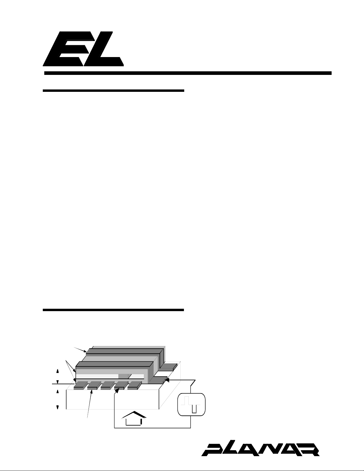
The EL glass panel is a solid-state device with a thinfilm electroluminescent layer sandwiched between
transparent dielectric layers and a matrix of row and
column electrodes. The row electrodes, in back, are
aluminum; the column electrodes, in front, are
transparent. The entire thin film device is deposited on a
single glass substrate. The glass panel is mounted to a
metal frame carrying the electronic circuit boards . The
result is a flat, compact, reliable and rugged display
device.
The display consists of an electroluminescent glass
panel and attached circuit boards with control electronics.
ALUMINUM ROW
ELECTRODE
DIELECTRIC
LAYERS
1 micron
LIGHT EMITTING LAYER
light emitting layer
The display has 640 column electrodes and
400 row electrodes arranged in an X-Y formation
with the intersecting areas forming pixels. Voltage
is applied to both the correct row electrode and
the correct column electrode to cause a lit pixel.
Operating voltages required are provided by an
integral DC/DC converter. The display utilizes a
frame buffer to capture video data and scan the
display at high (bright) refresh rates in Normal,
VGA, and buffered 8-bit FPD versions.
NOT FOR NEW DESIGNS
1 mm
TRANSPARENT
COLUMN ELECTRODE
GLASS SUBSTRATE
VIEW
V(t)
Page 2
EL640.400-CE Series
Electrical Characteristics
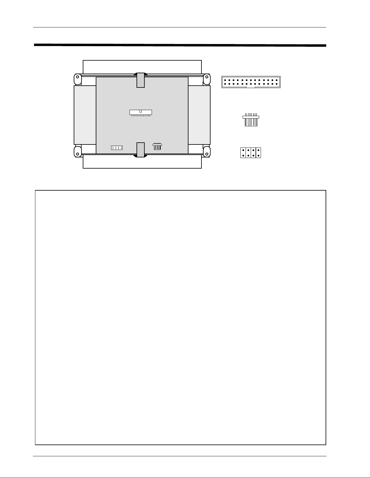
■ Connector Layout
To p
2
J1 Data/Power
Connector
2
26
1
25
J2 Luminance/
Contrast Control
1
PS1
1234
PS1
J1
J2
Fig. 1 The input connectors and jumpers on the EL640.400-CE Series display
■ Signal Inputs
Power/Video Input Connector (J1)
Symbol Pin Pin Symbol
VH (+12V) 1 2 VH +12V)
VL (+5V) 3 4 VL (+5V)
BLANK 5 6 GND
(TVID) VID
VS (S) 9 10 GND
HS 11 12 GND
VCLK 1 3 14 GND
(VID) VID
VID
VID
VID
VID
VID
Video signals and DC power are connected to the
display through a right angle, dual row header. The pin
assignments are shown in the tables above.
U1
U0
U2
L0
L1
L2
L3
7 8 8-BIT
15 16 GND
17 18 VID
19 20 GND
21 22 GND
23 24 GND
25 26 GND
U3
J1 Input Signal Descriptions
Symbol Functional Description
VCLK Video Clock. See timing diagrams for the definition of the active edge.
VID
U0-U3
VID
L0-L3
VID For the CE5 , CE6 this signal provides odd and even video pixel data in Single-Line mode, or even pixel data in 2-Bit Data Mode
TVID For the CE5 this signal provides odd column data in 2-Bit video mode.
HS Horizontal sync. See the appropriate display timing diagrams for active edge details.
VS Vertical sync. See the appropriate display timing diagrams.
(S)
VL (+5V) +5V Logic Supply voltage
VH (+12V) +12V supply for DC-DC converter and display analog circuits
GND Signal return for logic and power supplies
8- BIT This input is internally pulled to High state if not connected.
BLANK This input is internally pulled to High state if not connected.
For the CE4 display, these signals provide video pixel data to the upper half of the display. Pixel information is supplied from left
to right and from top to bottom (see page 7); the first bit of data on VIDU3 at the beginning of a frame is displayed at
the pixel in the upper left corner of the display. Bit number 160 of VIDU0 is at the upper right corner of the display. The data on
VIDU0-3 are displayed on the upper 200 rows of the display.
Same as VID
CE4 – This line must be High
CE5/CE6 – This line must be Low
CE4/CE5 – This signal must be High
CE6 – A low input level blanks the display. The trailing edge of blanking is used to position the display horizontally and sense the display mode.
(see above) but for the lower half of the display.
U0-U3
J2 Luminance/Contrast Control
LUM Input for external 50KΩ logarithmic pot to adjust the display luminance/contrast.
GND Signal ground return for LUM, L0, L1, and ENABLE.
L0 Digital refresh rate control LSB.
L1 Digital refresh rate control MSB.
ENABLE When the ENABLE line is pulled to a logic Low, the display stops scanning and emitting light. This gives a "sleep" mode for
minimum power, typically 1 Watt. This input is internally pulled to a high state if not connected.
Luminance/Contrast Control Connector (J2)
Pin Symbol
1 LUM
2GND
3L0
4L1
5 ENABLE
Page 3
EL640.400-CE Series3
■ CE Series Overview
The EL640.400-CE display can be ordered with
three interface options. T h e s e t h r e e d i s p l a y s a r e
mechanically and optically identical.
Display Video Interface
EL640.400-CE4 8-Bit Flat Panel Display (FPD)
Local frame buffer selected
by PS1 Jumper 4
EL640.400-CE5 EL Normal
EL640.400-CE6 VGA Modes
■ Connectors
Video/Power Input
J1 26-pin header T&B Ansley 609-2607 or
3M 2526-5002-UB, or equivalent
Mating
(customer supplied) T&B Ansley 609-2641CE or
3M 3399-6626, or equivalent
Luminance/Contrast Control
J2 5-pin header Hirose DF1-5P-2.5DS, or
equivalent
Mating
(customer supplied) Hirose DF1-5S-2.5R28 and
Hirose DF1-5A1.05, or equiv.
■ Luminance Control
The Luminance/Contrast control connector (J2)
provides analog control of display Luminance/
Contrast with a 50K ohm external potientiometer.
This analog dimming is available in all video modes.
Also, two bit digital dimming is available in all
modes except the 8-Bit non-buffered FPD mode
(see table).
■ 200 Rows Mode
Two hundred input data rows may be displayed
by automatically doubling every row of data. This
function is selected by installing Jumper PS1/2. This
is available only on the CE5 version of the display.
Contact Planar for more information on this mode.
■ Internal Frame Buffer
The CE display includes an internal frame
buffer. The brightness of the display is directly
proportional to the output frequency at the
frame buffer. The frame buffer frequency is
controlled by L0 and L1 on connector J2. When
the frame buffer is in use, loss of image will not
occur with loss of video input. The displayed
image is not automatically cleared.
Approximate
Refresh Rate L1 L0
160 H H
120 H L
75 L H
60 L L
(L1 and L0 are internally pulled high if not connected.)
The buffered, 8-Bit Flat Panel Display, VGA,
and Normal interfaces utilize the internal frame
buffer. The brightness of the display is
independent of the input frame rate. The f rame
buffer in the CE4 can be bypassed by removing
Jumper 4 on PS1 to allow input timing to control
the frame rate. This mode allows use of frame
rate gray scale algorithms. For optimum operation
in this mode, L1 and L0 should be high or left
disconnected.
■ Selectable Features
PS1 Jumper Description
Pin Name Function Applicable to
CE4CE5 CE6
1 SELFTEST Patterns Displayed xxx
2 200DBL 200 line mode. Each x
line of data is repeated
on the subsequent row
3 2-BIT Two-Bits-Parallel Mode x
4 Buffered FPD Refresh rate x
independent of input
frame rate. Remove
jumper when using
The PS1 jumper allows selection of several
modes. Factory default for CE5 and CE6 is no
jumpers installed. Factory default for CE4 is
jumpers 1 through 3 open and jumper 4 installed.
Caution
The EL640.400-CE displays include an internal frame buffer. The
displayed image is not automatically cleared in the absence of
input video signals. The ENABLE control input signal can be used to
blank the display in the event of system malfunction.
Page 4

EL640.400-CE Series
4
Input Specifications
Parameter Symbol Min. Max. Units
Video Input Signals:
Absolute Maximum Input Voltage V
Low-level Input Voltage V
High-level Input Voltage V
Low-level Input Current I
High-level Input Current I
All video signal inputs are CMOS compatible with 100Ω series resistors. A series resistor at the driven end of the video
cable will reduce overshoot and undershoot. Generally, the resistor value should be equivalent to the impedance of the
DC Input Requirements
Input Voltage (nom=12.0V) VH 10.0 15.0 Vdc
Input Voltage Absolute Max. VH
Input Current (VH=12.0) IH 0.250
Refresh Rate=60Hz 1.0 Adc
Refresh Rate=160Hz 2.1 Adc
Logic Voltage (nom=5.0V) VL 4.75 5.25 Vdc
Logic Voltage Absolute Max. VL
Logic Current IL 25 185 mAdc
Power Consumption Typical Max. Units
Refresh Rate=60Hz 6.5 12.5 Watts
Refresh Rate=160Hz 12.6 25 Watts
Imax
IL
IH
IL
IH
max
max
-0.3 5.5 V
-0.3 0.5 V
4.5 5.0 V
— -0.4 mA
— 10 µA
cable.
–– 15.0 Vdc
-0.5 6.0 Vdc
■ Video Interfaces
The CE series displays make it easy to interface to
different display controllers. The interfaces are: 8-bit
FPD (CE4), Normal (CE5), and VGA (CE6).
The EL640.400-CE4 with its 8-bit FPD interface is
designed for easy interfacing to flat panel controller
IC's. The falling edge of VCLK simultaneously latches
four data bits into the top half of the display and four
bits into the bottom half of the display. This low speed
clock can be an asset in reducing EMI. The 8-bit FPD
interface allows access to gray scale algorithms
generated in video controller chips which can result in
4 to 5 levels of gray scale at 60 Hz. More levels are
available at higher frame rates. For further information,
contact factory.
The EL640.400-C5 is backward compatible with
some earlier Planar displays. This interface is pin and
timing compatible with the MD640.400 and EL640.400CB series displays. There are only four necessary input
signals: serial video data (VID), video clock (VLCK),
horizontal synchronizing control (HS) and vertical
synchronizing signal (VS). The fifth signal, BLANK, is not
used and should be high or left disconnected.
Horizontal data position is determined in the Normal
mode by the relationship between the falling edge of HS
and the input data VID. The first 640 pixels after the
rising edge of HS are displayed.
Vertical position is determined by the relationship
between VS and HS. The data displayed on the first or
top row is determined by the location of the VS rising
edge.
The first row of a new frame is marked by the rising
edge of VS during the HS high time. Data clocked into
the display during this HS period will be displayed on the
first row. See timing diagram for detailed timing.
In the normal mode it is possible to feed the input
data in two line parallel mode to reduce the input data
and clock frequencies. The data for the odd columns,
as numbered from left to the right from the viewers side,
should be connected to the TVID input (J1/ pin 7) and the
data for the even columns to the VID input (J1/ pin 15).
The EL640.400-CE6 display is compatible with the
IBM VGA feature connector standard. The display can
directly use the signals available via the feature connector
on IBM compatible VGA cards. The display is compatible
with most VGA modes. The display assumes VGA
standard borders. In 720 column modes, every ninth
pixel is skipped. The ninth pixel is either a redundant
character pixel or an extra space pixel so no data is lost.
In VGA modes requiring 480 rows, the first 400 lines of
data will be displayed. The last 80 lines of data are
ignored.
Page 5

EL640.400-CE Series5
■ 8-Bit FPD Interface (CE4)
This diagram illustrates the pattern of displayed data while in the 8-Bit FPD video mode.
Key: [
Video Data Line: Row In Frame, Data Bit In Row
]
The data bits for 8 pixels per clock are sent to the display. For instance, 4 pixels
(U3:1,1-U0:1,1) are sent to row 1 at the same time as four pixels (L0:1,1-L3:1,1)
are sent to row 201. At the next clock, (U3:1,2-U0:1,2) are sent at the same time
as (L3:1,2-L0:1,2).
Num. Description Symbol Minimum Maximum Units
1 HS High time tHS
2 HS Low time tHS
3 HS setup to VCLK tHS
4 VID setup to VCLK tVID
5 VID hold from VCLK tVID
6 Video clock period tVCLK 150 -- nsec
VCLK rise, fall time tVCLK
7 VCLK low width tVCLK
8 VCLK high width tVCLK
9 VS (S) high setup to HS¯ tVS
10 VS(S) hold after HS¯ tVS
11 VCLK to HS allowance 0 -- nsec
H
L
SU
SU
HD
RF
L
H
HSU
HD
12 HS period tHS 30.6 + t
13 VS (S) period tVS 200 --
Frame rate tVS -- 160 Hz
Frame time tVS 6.25
14 HS rise to VCLK fall tHSrVf 890 -- nsec
15 HS rise to VSrise tHSrVSr -- 62 nsec
Notes:
t
HSL > tHS - tVS
1)
is less than number 1]
[in figure above number 12 - number 9], where tVS
HSU
2) In the Buffered mode of operation the first 160 valid video data nibbles (Upper and Lower) after thefalling
edge of HS are displayed. In the Non-Buffered mode of operation, the last 160 nibbles of video data
prior to the rising edge of HS are displayed.
3) No more than 255 pixel clocks per line.
20 -- nsec
160
1
--
t
VCLK
95 -- nsec
5 -- nsec
10 -- nsec
-- 30 nsec
20 -- nsec
20 nsec
50 nsec
40 -- nsec
-- usec
HS
< tHSH [in figure above number 9
HSU
t
HS
Page 6

EL640.400-CE Series
6
■ 640 x 400 EL Normal Mode Video Input Timing (CE5)
Line Timing
22
VCLK
133
VID
(TVID)
4 5
Pixel 1 Pixel 2 Pixel 640
6 7
6 7
HS
Frame Timing
8
HS
9
VS
Num. Description Symbol Minimum Maximum units
1 Video clock period - single line video tVCLK 34 -- nsec
- 2-bit video tVCLK 68 -- nsec
2 VCLK rise, fall time tRF 8 nsec
3 VCLK low width tWL 8 -- nsec
4 VID setup to VCLK tSVID 8 -- nsec
5 VID hold from VCLK tHVID 8 -- nsec
6 HS hold from VCLK rise tHHS 8 -- nsec
7 HS setup to VCLK rise tSHS 8 -- nsec
8 HS low time
9 VS hold from HS tHVS 9 -- tVCLK
1 0 V S s et u p t o H S t VH S 1 0 0 - - nsec
11 VS high/low width tVSW 1 - - tVCLK
12 HS period tHS 21.3 (See Notes 3,4) µsec
13 VS period Normal tVS 40 0 -- tHS
VCLK high width tWH 8 - - nsec
1
200 Line fVS 200 -- tHS
Frame rate -- 160 Hz
12
Line 1 Line 2
10
11
tH SL 4 - - tVCLK
11
13
Note: 1. VCLK must be running during HS low time.
2. The first 640 pixels after the rising edge of HS are displayed.
3. HS high time must be a multiple of 8 tVCLKS.
4. The display will properly operate with up to 1023 pixels in a horizontal high time interval.
Page 7

Timing Characteristics (CE6)
350, 400, and 480 Row VGA Modes (CE6)
EL640.400-CE Series7
Frame Timing
VS (350/480 ROW)
VS (400 ROW)
HS
BLANK
Last Row
T1
Video Data
Line Timing
350 Row Modes (IBM Modes: 2*,3*,F,7,10)
T 1 Vertical Border
T 2 Vertical Front Porch132 tHS
T 3 VS Pulse Width
T 4 Vertical Back Porch153 tHS
T 5 Vertical Border 6 tHS
1
1
HS (350 ROW)
HS (400/480 ROW)
BLANK
Video
unit
6 tHS
2 tHS
Last Pixel
T6 Horizontal Border
T 7 Horizontal Front Porch
T8 HS Pulse Width >64,<99 > 1 0 0 tVCLK
T 9 Horizontal Back Porch 40
T1 0 Horizontal Border 8 9 tVCLK
HS pulses / VS 449
VS frequency 7 0 H z
Sync Pulse Polarity Positive Negative
Sync Level at Rising Edge of BLANK Low High
Mode Determined
Row 1
T4
T2
t
T3
HS
T5
T7
T6
VCLK pulses / HS 800 900
HS period(typ.) 3 1. 8 3 1. 8 us
T8
1
1
HS VS
T9
T10
Pixel 1
640 720 unit
8 9 tVCLK
1 1 9 tVCLK
1
45
1
tVCLK
400 Row Modes (IBM Modes: 2,3,2+,3+,6,+,E,)
T 1 Vertical Border
T 2 Vertical Front Porch16 tHS
T 3 VS Pulse Width
1
1
7 tHS
2 tHS
T 4 Vertical Back Porch127 tHS
T 5 Vertical Border 7 tHS
HS pulses / VS 449
VS frequency 7 0 H z
unit
T6 Horizontal Border
T 7 Horizontal Front Porch
1
1
T8 HS Pulse Width >64,>99 > 1 0 0 tVCLK
T 9 Horizontal Back Porch 3 71/401401/45
T1 0 Horizontal Border 8 9 tVCLK
VCLK pulses / HS 800 900
HS period(typ.) 3 1. 8 3 1.8 us
Sync Pulse Polarity Negative Positive
HS VS
Sync Level at Rising Edge of BLANK High Low
480 Row Modes (IBM Modes: 11,12)
T 1 Vertical Border
T 2 Vertical Front Porch13 tHS
T 3 VS Pulse Width
T 4 Vertical Back Porch124 tHS
T 5 Vertical Border 8 tHS
HS pulses / VS 525
VS frequency 7 0 H z
1
1
8 tHS
2 tHS
unit
T6 Horizontal Border
1
T 7 Horizontal Front Porch
1
640 unit
8/11 tVCLK
T8 HS Pulse Width >64,< 9 9 tVCLK
T 9 Horizontal Back Porch 40 tVCLK
T1 0 Horizontal Border 8 tVCLK
VCLK pulses / HS 800
HS period(typ.) 3 1.8 us
HS VS
Sync Pulse Polarity Negative Negative
1
Ignored by display controller, values are for typical system timing. The first 320, 360, 640 or 720 pixels after T10 are displayed.
Sync Level at Rising Edge of BLANK High High
640 720 unit
8 9 tVCLK
8/11 9/13 tVCLK
8 tVCLK
1
tVCLK
Page 8

EL640.400-CE Series
8
Supported VGA Modes
(CE6) (CE6)
(CE6)
(CE6) (CE6)
VGA Type Text Char. Vsync Pixels Double Border size
mode format box freq. (Hz) (software) scan h v
2, 3 text 80 x 25 8 x 8 70 640 x 200 yes 8 7
2*, 3* text 80 x 25 8 x 14 70 640 x 350 no 8 6
2+, 3+ text 80 x 25 9 x 16 70 720 x 400 no 9 7
6 graphics 80 x 25 8 x 8 70 640 x 200 yes 8 7
7 text 80 x 25 9 x 14 70 720 x 350 no 9 6
7+ text 80 x 25 9 x 16 70 720 x 400 no 9 7
E graphics 80 x 25 8 x 8 70 640 x 200 yes 8 7
F graphics 80 x 25 8 x 14 70 640 x 350 no 8 6
10 graphics 80 x 25 8 x 14 70 640 x 350 no 8 6
11 graphics 80 x 30 8 x 16 60 640 x 480 no 8 8
12 graphics 80 x 30 8 x 16 60 640 x 480 no 8 8
NOTES
In VGA modes 2+, 3+, 7 and 7+ the character box width is narrowed to 8 pixels by omitting the data of every 9th pixel.
Necessary picture adjustments may be done by programming the registers of the VGA controller chip.
Double Scan is a VGA card feature. The display will show the first 400 lines of the 640 by 480 graphic modes. In 350 line modes
the image is top justified.
VGA Video Setup and Hold Timing
VS
HS
BLANK
V
CLK
D0-D3
t
SU
t
V
CLK
t
SU
Min.
Setup Time, t
Hold Time, t
SU
HOLD
4 nS
4 nS
■ EMI Performance (CE4, CE5, CE6)
The EL640.400-CE series displays are designed
for low EMI emissions, and low susceptibility to EMI
interference. In general, radiated EMI problems
are related more to the opening a display makes
in an enclosure than the emissions from the display.
The Planar 640.400-CE displays incorporate a metal
internal frame that mechanically supports the
t
Hold
t
Hold
display and also serves as an EMI shield. This
internal EMI shield can make system level EMI
certification significantly easier and faster.
The tapped mounting holes are an integral
part of the metal frame. The frame is isolated
from the signal/power supply grounds.
Caution
Properly mounted, this display can withstand high shock loads as well as
severe vibration in aggressive environments. However, the glass panel used in
this display will break when subjected to bending stresses, high impact or
excessive loads.
Page 9

Operational Specifications
EL640.400-CE Series9
■ Environmental
Temperature
Operating - 25...+65°C
Non-operating -40...+75°C
Operating Survival
(no permanent damage) -40...+70°C
Humidity
Operating 40°C at 95% RH (w/o cond.)
Test duration 120 h (per IEC 68-2-3)
Reliability (MTTF)
30,000 hours min.
Altitude
Operating 15 000 m (50 ,000ft.) above sea level
Vibration
Random vibration wide band IEC 68-2-36, Test Fdb
20...500Hz frequency range
ASD level -3 dB/oct (500 Hz, 0.02 g2/Hz)
Total r.m.s. acceleration 1.9 g
Duration of endurance 3 x 30 min
■ Optical
Display Color
Peak wavelength (typ.) 585 nm, yellow
Luminance
Pixel @ 60 Hz refresh 30.8 cd/m2 (9.0 fL) min.
@160 Hz refresh 82.2 cd/m2 (24.0 fL) min.
Areal @ 60 Hz refresh 18.6 cd/m2 (5.42 fL) min.
@160 Hz refresh 49.7 cd/m2 (14.5 fL) min.
Luminance Contrast Ratio
@160 Hz refresh 13:1 min, @ 1,500 lx
5:1 min, @ 5,000 lx
2.2:1 min, @ 15,000 lx
Illuminance Classification
1 … 10 lx dark
10 … 100 lx dim
100 … 1000 lx office
1 000 … 10 000 lx bright
10 000 … 100 000 lx sunlight
Note: The luminance specification is
comparable to standard EL displays with a 33%
transmissive contrast enhancing filter at the
ShockIEC 68-2-27, test Ea
Magnitude 100 g
Duration 6 ms (half sine wave)
Number of shocks 18 (3 on each of the
6 surfaces)
NOTE: Unit is not operating during shock tests. Unit is
mounted using all four mounting nuts.
Viewing Angle > 160
o
Safety
The display will not inhibit the end product from
obtaining any of the following certifications: UL1950,
UL 2601, IEC950, IEC 601-1.
Electromagnetic Compatibility
The displays are capable of meeting the
requirements of FCC Part 15, Subpart J, Class B; VDE
0871 Level B; EN55011, Level B; and EN55022, Level B
when housed in suitable enclosure.
Luminance Stability
Luminance variation (time) 20% max. in 10,000 h
Luminance variation (temp.) 10% typical
15% max.
-25..... +65o C range
Luminance deviation within the display <35%
Fill Factor
60.2% luminance area/total active area.
same refresh rate.
ICE
TM
Integral Contrast Enhancement (ICETM)
incorporates a new thin film layer in the EL
structure which significantly reduces light
reflections from the display's rear electrode.
The EL640.400-CE series is the ICETM version of
the display, and offers the following
performance advantages:
-inherently higher display contrast
-crisper display images
-a lower cost solution for the display
system user.
Page 10

EL640.400-CE Series
Mechanical Characteristics
10
■ Display External Dimensions
Fig. 2 (pg. 11) shows the mechanical dimensions of the
standard EL640.400-CE Series display unit. See Ordering
Information on page 12.
Height 172 mm (6.8 in.)
Width 225.0 mm (8.8 in.)
Depth 20.5 mm (0.8 in.)
Weight 550 g (19 oz.)
CAUTION: T h e f r e e a i r t emperature near the display should not exceed environmental
specifications (see page 10). In most applications, an air gap of approximately 5 mm is
recommended (see mechanical drawings). Some applications may require, however, a
larger air gap to cool the display unit in the system. Note that this may slightly increase the
total depth of the design.
Installation and Handling
■ Display Viewing Area Characteristics
Active area
Height 122 mm (4.80 in.)
Width 195 mm (7.68 in.)
Pixel pitch
Height 0.305 mm (0.012 in.)
Width 0.305 mm (0.012 in.)
Pixel size
Height 0.236 mm (0.0093 in.)
Width 0.236 mm (0.0093 in.)
■ Mounting
Mounting of the EL640.400-CE should utilize the M3
threaded inserts in the four corners of the mounting
frame.
■ Handling
The display is made of glass material and should be
handled with proper care. Do not drop the display or
allow hard objects to strike its surface.
Electrostatic Caution
The Planar display uses CMOS and power MOSFET devices. These components are electrostatic
sensitive. Unpack, assemble and examine this
assembly in a static-controlled area only. When
shipping use packing materials designed for
protection of electrostatic-sensitive components.
■ Cable Length
For trouble-free data transfer from data
transmitter to display input connector, a maximum
cable length of 600 mm (24 in.) is recommended. In
order to lower signal reflections and system noise,
the video lines in the connecting cable should be
source terminated with series resistors matching the
characteristic impedance of the cable.
■ Avoiding Burn-in
As with any other light emitting display, luminance
variations may be noticed if fixed patterns are
displayed on the screen for extended periods. It is
prudent to use a screen saver or image inversion to
avoid burn-in.
Warning
The product generates potentially dangerous
voltages capable of causing personal injury (high
voltage pulses up to 250 VAC). Do not touch the
display electronics during operation!
Page 11

EL640.400-CE Series11
Fig. 2. EL640.400-CE Series display front view, bottom view, and side view.
Page 12

EL640.400-CE Series
®
12
Description of Warranty
This description is not the full warranty, and should
not be construed as a substitute for the full warranty. A
copy of the full warranty is available upon request.
Planar warrants that the goods it sells will be free of
defects in materials and workmanship, and that these
goods will substantially conform to the specifications
furnished by Planar, and to any drawings or specifications
furnished to the Seller by the Buyer if approved by the
Seller. This warranty is effective only if Planar receives
notice of such defect or nonconformance during the
period of warranty, which begins the day of delivery.
The goods Planar sells are warranted for a period of
one year unless otherwise agreed to by Planar and the
Buyer. The Buyer must return the defective or nonconforming goods, upon request, to Planar not later
than 30 days after Planar’s receipt of notice of the
alleged defect or non-compliance. Buyer shall prepay
transportation charges, and Planar shall pay for return
of the goods to the Buyer. No goods are to be returned
to Planar without prior permission.
The warranty does not apply in cases of improper or
inadequate maintenance by the Buyer, unauthorized
modification of the goods, operation of the goods
outside their environmental specifications, neglect or
abuse of the goods, or modification or integration with
other goods not covered by a Planar warranty when such
modification or integration increases the likelihood of
damage of the goods.
Easy to Use
There are many options available which make
Planar flat panel displays easy to use, easy to
interface, and easy to package. Call Planar for
complete information.
Support and Service
Planar is a US company based in Beaverton,
Oregon and Espoo, Finland with a world-wide
sales distribution network. Full application
engineering support and service are available to
make the integration of Planar displays as simple
and quick as possible for our customers.
RMA Procedure: For a Returned Material
Authorization number, please contact Planar
International Ltd., or Planar Systems, Inc., with
the model number(s) and original purchase order
number(s). When returning goods for repair,
please include a brief description of the problem,
and mark the outside of the shipping container
with the RMA number.
Ordering Information
EL640.400-CE4 8-bit FPD and buffered 8-
bit FPD interface
EL640.400-CE5 Normal, EL interface
EL640.400- CE6 VGA, Feature connector
interface
Represented by:
Planar and "The Definition of Quality" are registered
trademarks of Planar Systems, Inc.. ICE™ is a trademark of
Planar Systems, Inc.
North & South American Sales:
Planar America, Inc.
1400 NW Compton Drive
Beaverton, OR USA 97006-1992
Tel: 503/690-6967
Fax: 503/690-1493
4-96
European & Far East Sales:
Planar International Ltd.
P.O. Box 46
FIN-02201 Espoo, Finland
Tel: +358-0-42001
Design and specifications subject to
change without notice.
The Definition of Quality
Government & Specialty Sales:
Planar Advance, Inc.
P.O. Box 4001
Beaverton, OR USA 97076-4001
Tel: 503/614-4111
Fax: 503/614-4101
Copyright 1996 © Planar America, Inc. All rights reserved.
Page 13

...............(part #) Revision History
Ver Date Page/Section Description of change
1. 8/94 "Advance Information"
Initial Version
2. 10/94 2/Signal inputs Revised
3/Connectors Added Hirose DF1-5A 1.33
3/Input specs. Input current changed to 0.250
4/Disp.Op.Modes Corrrected C&T controller 65530
5/Add'l features Deleted 'Low power mode' and
'Picture Position Fine Setting'
9/Humidity 'Non Operating' and 'Condensation'
statements removed
9/Reliability Changed to 30,000 hrs.
9/Random vibration Removed frequency range
9/Color 585nm, yellow
9/Luminance
Contrast Ratio Adjusted
EL640.400-CE Series13
3. 5/95 3/PSI Jumper Desc. Expanded to include CE4, CE5, CE6
4/Supported Video
Modes Include -04, -05, -06
8/Input Timing Replaced "standard" with "normal" in title to make
reference consistent throughout the document
8/ Added "cautionary statement" in event of malfunction
9/ICE Added paragraph on ICE
TM
11/Fig.2 Clarified drawing
12/Ordering Info. Deleted CE1, inserted CE4, CE5, CE6
4 9/95 3/PSI Jumper desc. Revised for CE4, CE5, CE6
4/Video interfacesRevised last sentence of para. 4.
5/FPD interface Added note 3 at end of table
6/Normal interface Added notes 3 and 4 at end of table
7/350 row modes Deleted "320"
7/400 row modes Deleted "320" and "360"
7/480 row modes Deleted IBM Mode 12
8/VGA modes Deleted the following modes 0, 1 ; 0*, 1*; 0+, 1+; 4,5;
D and 13. Corrected notes
5 4/96 1/Deleted "Advance Information"
3/Luminance/ Corrected Hirose model numbers
Contrast Control
3/Internal Frame Added last sentence to 3rd paragraph
Buffer
5/Timing Diagram Corrected timing in both diagram and table
for CE4. Added lines 14 and 15 to table.
12/Added "Planar Advance"
Page 14

EL640.400-CE Series
14
 Loading...