

Page 1
EL4836LP and EL4836LP-ICE
EL
276 x 128 Pixel Electroluminescent Display
Product Profile
The EL4836LP and the EL4836LP-ICE displays are low
power, rugged, high-resolution electroluminescent (TFEL)
flat panel displays. They replace the LCD or bulky CRT in
instrument product designs. Their compact dimensions
save space that can allow addition of features or reductions
in overall size. They are designed to function in extreme
environments, and the crisp displays are viewable under
most lighting conditions at wide viewing angles. Their ease
of installation reduces system integration costs.
The EL4836LP and the EL4836LP-ICE are 276 column
by 128 row displays with a resolution of 48 dots per inch.
The pixel aspect ratio is 1:1. The LCD-type interface is
TTL-compatible and is designed for hardware compatibility
with the Hitachi HD61830B or equivalent LCD controller.
These displays may be driven at frame rates up to 120 Hz for
applications requiring extra brightness.
The displays require DC power and four basic signals to
operate:
1. Video Data or pixel information (VID)
2. Video Clock, pixel clock, or dot clock (VCLK)
3. Horizontal Sync (HS)
4. Vertical Sync (VS)
EL Technology
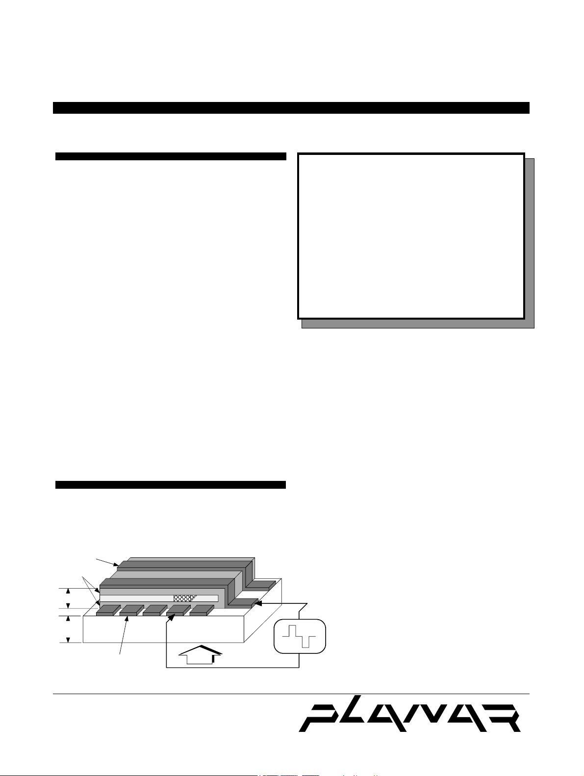
A display consists of an electroluminescent glass panel
and a mounted circuit board with control electronics.
ALUMINIUM ROW
ELECTRODE
DIELECTRIC
LAYERS
1 micron
1 mm
LIGHT EMITTING LAYER
TRANSPARENT
COLUMN ELECTRODE
GLASS SUBSTRATE
VIEW
Operations Manual
The EL glass panel is a solid-state device with a thin film
luminescent layer sandwiched between transparent dielectric
layers and a matrix of row and column electrodes. The row
electrodes, in back, are aluminum; the column electrodes, in
front, are transparent. The entire thin film device is deposited
on a single glass substrate. A circuit board is connected to
the back of the glass substrate. Components are mounted on
this circuit board within the same area as the electroluminescent viewing area on the glass panel. The circuit
board is connected to the glass with metal-on-elastomer
interconnect technology. The result is a flat, compact,
reliable and rugged display device.
The EL4836LP-ICE display includes a light absorbing
Integral Contrast Enhancement (ICETM)
construction of the display glass. ICETM background
significantly improves the luminance contrast of
the display in bright ambients, and makes the
display easier to read by increasing the crispness of
the pixels.
The 276 column electrodes and 128 row
electrodes are arranged in an X-Y formation with
the intersecting areas performing as pixels. Voltage
V(t)
is applied to both the correct row electrode and the
correct column electrode to cause a lit pixel.
Operating voltages required are provided by a DC/
DC converter.
The Definition of Quality ®
®
Page 2
2EL4836LP, EL4836LP-ICE
Electrical Characteristics
Display
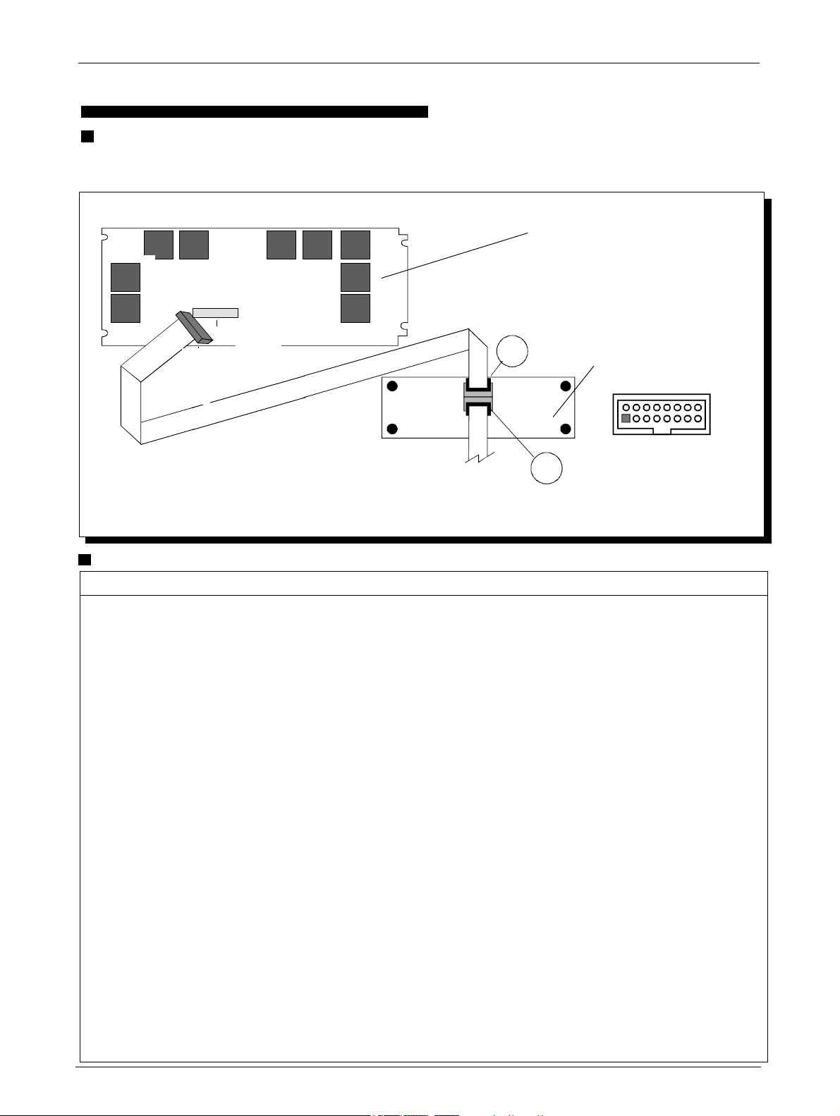
The EL4836LP and EL4836LP-ICE products consist of a display, a DC/DC converter, and interconnecting cable as
shown below.
Back of Display
J1
J1
P3
P1
P1
1
2
J3
J0
DC/DC Converter
2
16
J1
19 20
P0
P0
1
J0
15
Input to the Display at P0
Pins Signal Symbol Description
1, 2 Voltage VH +12V. See also the descriptions of DC power requirements on page 4.
3, 4 Voltage VL +5V optional input, see page 4.
5 not connected
6 not connected
7, 8, 10
12, 14, 16 Ground GND Signal return.
9 Vertical Sync VS A new frame is initiated by the high state of VS. To properly sync the EL display, VS must be high at
11 Horizontal Sync HS HS marks the last pixel of a horizontal scan line. HS period must be an even multiple of 4 tVCLK. The
13 Video Clock VCLK VCLK provides the necessary signal to latch in the information present on VID. The VID and HSsignals
15 Video Data VID VID contains the serial video data to be displayed. A logic high corresponds to a lit pixel.
the end of line 1. This signal passes directly from the user to the display via the DC/DC converter. It is
not buffered or terminated within the DC/DC converter.
last 276 pixels prior to the falling edge of HS will be visible on the display. This signal passes directly
from the user to the display via the DC/DC converter. It is not buffered or terminated within the DC/DC
converter.
are referenced to VCLK, which must run continually. Video data latch occurs on the falling edge of
VCLK. This signal passes directly from the user to the display via the DC/DC converter. It is not buffered
or terminated within the DC/DC converter.
Pixel information on VID is supplied from left to right and from top to bottom; the first bit
of data on VID at the beginning of a frame is displayed as the pixel at the upper left corner of the display.
Bit number 276 is at the upper right corner. Bit number 277 is directly beneath pixel number 1 and so
on. This signal passes directly from the user to the display via the DC/DC converter. It is not buffered
or terminated within the DC/DC converter.
Page 3
3 EL4836LP, EL4836LP-ICE
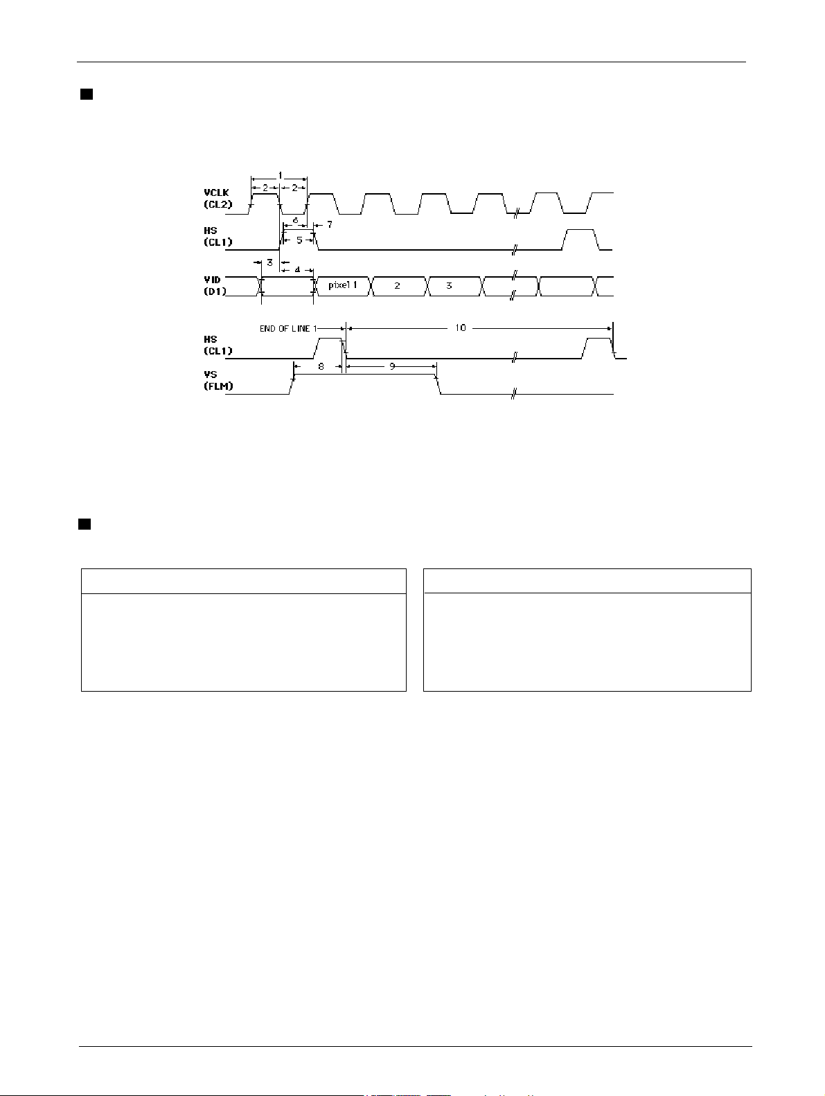
LCD Hardware-compatible Video Timing Input at PO
275
276
Video Parameters
Parameter (Symbol) Min. Max. Units
1 Video clock (CL2) period (tVCLK) 235 630 ns
2 VCLK lowtime (tWL) 1 00 — ns
VCLK high time (tWH) 100 — ns
3 VID setup to VCLK (tDS) 5 0 — ns
4 VID hold from VCLK (tDH) 5 0 — ns
5 HS (CL1) high time (tHS high) 100 tVCLK ns
Parameter (Symbol) Min. Max. Units
6 HS setup time (tHSS) 100 tWL ns
7 HS hold from VCLK (tHSH) 0 tWH ns
8 VS (FLM) setup to HS (tHSD) 400 — ns
9 VS hold from HS (tVSD) 1000 — ns
HS (CL1) period (tHS) 276 — tVCLK
VS period (tVS) 128 — tHS
Frame Rate (1/VS period) 120 Hz
Page 4
4EL4836LP, EL4836LP-ICE
Video Electrical Specifications
Symbol Parameter Min. Max. Units
VIL low-level input voltage - 0.3 0.8 V
maximum input voltage — 5.25 V
VIH high-level input voltage 2.4 5.0 V
IIL low-level input current — - 0.4 mA
IIH high-level input current — 10 µA
VOH output high voltage 2.0 V
@ IOH= 0.4 mA
VOL output low voltage 0.4 V
@ IOL = 2.1 mA
Note: All inputs are TTL-compatible CMOS with 24KΩ
pull-up resistors and 100Ω series resistors (to minimize
under- and over-shoot of input signals).
DC/DC Converter - PS512-1
The display and the separate DC/DC converter are calibrated together at the factory. Replacements to these
matched units must be adjusted according to specifications. Consult Planar for design specifications.
DC Power Consumption
Power is dependent on the actual text or graphics displayed. For a typical screen of text and graphics, power
is under 1.3 watts. Maximum power is 1.8 watts at 60 Hz frame rate and 3.0 watts at 120 Hz.
DC Power Input Specifications
Description Min. Nom. Max. Units
Input voltage (VH) 10.8 12.0 13.2 VDC
Input voltage
absolute max. (VH) — — 15.0 VDC
Input current (IH)
VH=Min, 240 Hz frame rate — — 0.4 A
Optional 5V (VL) 4.75 5.0 5.25 VD C
Absolute max. (VL) — — 7.5 V DC
Input current (IL) — — 0.04 A
DC/DC Converter Calibration - PS512-1
The DC/DC converter cannot be tested separately.
It requires an active low enable signal from the display
to activate the high voltage section. The display provides this signal after detecting the presence of video
signals at its input.
The DC/DC converter has been properly calibrated
at the factory to the EL display by means of a voltage
output adjustment. The converter should not need
adjustment in the field. If the DC/DC converter and
display become separated the following procedure
can be used to reset the the proper voltage:
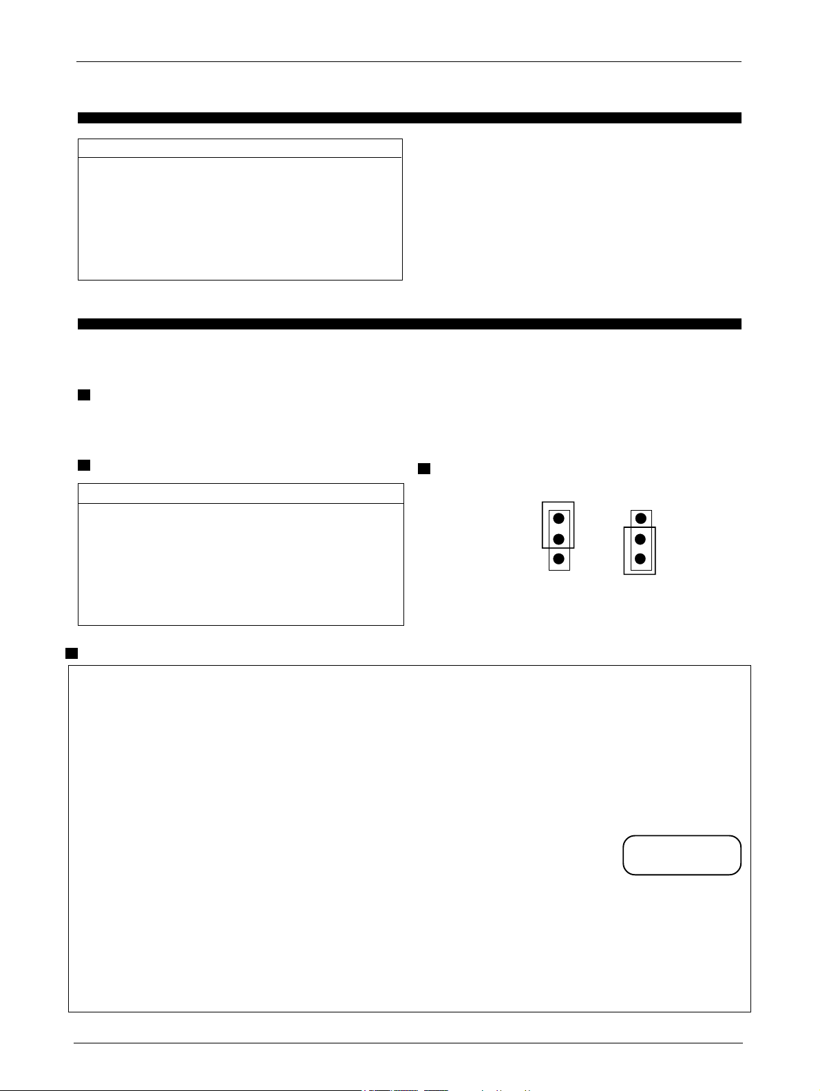
JP1 Function
INT
J1
1
2
3
EXT = +5V (VL) supplied by customer from an
external source.
INT = +5V (VL) generated from VH within the
DC/DC converter. Shipped set for INT from factory.
4. Apply a full on video pattern to the display (full
white field). At the factory, calibration is done with all
pixels on.
5. Set the DVM to measure a 250VDC voltage.
6. Connect the positive lead of the DVM to HV2 test
point. Connect the ground lead of the DVM to GND test
point on the DC/DC converter. See drawing on p. 7.
7. Apply power to the DC/DC converter.
8. Note the voltage statement
on the display. A sample is shown
at right:
EXT
JP1JP1
J1
1
2
3
PS SN: __________
V(ALL ON):+______
1. Ensure power to the DC/DC converter is off.
2. Turn trimpot on the DC/DC converter fully
counterclockwise (ccw).
3. Connect the DC/DC converter to the display using the
flat cable.
9. Adjust the R20 trimpot on the DC/DC converter
clockwise (cw) until the voltage reading of the DVM is equal
to the V (ALL ON) voltage ±1V, as specified on the display.
Do NOT exceed 235V. Do NOT adjust R19.
10. Calibration is complete.
Page 5

Operational Specifications
5 EL4836LP, EL4836LP-ICE
Environmental
Temperature
Operating 0°C to +55°C
Operating Survival -20°C to +70°C
Non-Operating -40°C to +75°C
Humidity
95% relative humidity (non-condensing) as verified by
MIL-STD-202F method 106E.
Altitude
Operating 15,000 ft. (4,572 m) above sea level
Non-Operating 50,000 ft. (17,678 m) above sea level
Non-Op Pressure 6 Atm for 1 hour
Vibration (Operating)
5-25 Hz:
Sweetptime 10 min ea. axis, 1 min sweep rate
Amplitude 0.100 inches p-p displacement
Dwell at resonance 15 min each axis
25-55 Hz:
Sweetptime 5 min ea. axis, 1 min sweep rate
Amplitude 0.060 inches p-p displacement
Dwell at resonance 15 min each axis
If no resonance is found, dwell is performed at 55Hz, 0.0600
inches p-p displacement, for 15 minutes.
Optical
Display Color
Peak wavelength (typ) 585 nm, Yellow-Orange
Pixel Luminance
ON luminance Typ. Min.
EL4836LP
at 60 Hz 50 fL (171) 30fL (103 cd/m2)
at 120 Hz 100 fL (342) 60fL (206cd/m2)
EL4836LP-ICE
at 60 Hz
at 120 Hz
Luminance measured at center of display screen, full ON
pattern, 25°C ambient. Note: the Hitachi 61830B LCD
controller is limited in frame rate and will not drive the
display to its maximum brightness potential.
OFF luminance
EL4836LP 0.3 fL maximum (0.7 cd/m2)
EL4836LP-ICE
Luminance measured at center of display screen, 60 Hz
frame rate, full OFF pattern, 25°C ambient.
ON luminance uniformity, maximum difference ≤26%
Measured between any two of five points (corners and
center): Non-uniformity %= (1 - min luminance/max
luminance) x 100.
Vibration (Non-Operating)
55-500 Hz:
Sweetptime 120 min ea. axis, 3.2 min sweep rate
Amplitude 3 g peak acceleration
Dwell at resonance 30 min each axis
Dwell performed at all resonances of g(out) / g(in) ≥5.
Shock
Magnitude 50 g peak acceleration
Duration 4 ms (half sine wave)
Number of tests 3 on each of 6 surfaces
Mean Time to Failure
Greater than 30,000 hours
Electromagnetic Compatibility
The display is capable of being operated in a final product
that complies with FCC Docket, Part 15, Subpart J, class B.
The bezel is electrically isolated from the display circuit
nodes.
ICE
Integral Contrast Enhancemen (ICETM) incorporates a new
thin film layer in the EL structure which significantly
reduces light reflections from the display's rear electrode.
The EL4836LP-ICE is the ICETM version of the EL4836LP
display, and offers the following performance advantages:
TM
-inherently higher display contrast crisper display images
-a lower cost of solution for the display user
ON luminance variation (temp.) max. variation ±15%
from 25°C over 0°C to +55°C range.
ON luminance variation (time), max. difference ±10%
at 25°C within 10,000 hours.
Luminanace Contrast Ratio
8:1 min, @ 500 lux
3:1 min, @ 2000 lux
Fill Factor
30.6% luminance area/total active area.
Viewing Angle
Greater than 160° viewing cone.
Safety and Health
Safety
The display will not inhibit the end product from obtaining
any of the following certifications: UL114/478, CSA 154,
IEC 380.
Health
An inert, non-toxic, silicon-based oil is used in the
construction of the electroluminescent panel.
Page 6
6EL4836LP, EL4836LP-ICE
Installation and Handling
Unpacking
Electrostatic Caution
The Planar display and DC/DC converter assemblies use CMOS and power MOS-FET devices. These
components are electrostatic sensitive. Unpack, assemble and examine these assemblies in a staticcontrolled area only. When shipping either assembly,
use packing materials designed for protection of
electrostatic-sensitive components.
Unpack and check contents of shipping container
against invoice in a static-controlled area. Use antistatic bags for storage of displays and DC/DC converters awaiting assembly processes. Any discrepancies in materials received and invoiced should be
noted to Planar within 10 days.
Mounting and Connector Locations
This display has no mounting holes and is designed for
clamp mounting similar to an LCD. Do NOT clamp the
display by its circuit board. Mounting compression should
be made only on the metal bezel itself. Connector locations
are shown on Page 7.
Cleaning
Display Face Any non-abrasive mild
glass cleaner can be used.
Mechanical Characteristics
Display External Dimensions
Height 3.885 in. 98.68 mm
Width 6.964 in. 176.88 mm
Depth 0.575 in. 14.60 mm
Weight (max) 9.5 oz. 270 grams
Recommended air gap behind display places total
depth at 0.75 in (19.04 mm).
DC/DC Converter Characteristics
Height 2.00 in. 50.8 mm
Width 5.25 in. 133.4 mm
Depth 0.75 in. 19.1 mm
Weight 3 oz. 85 grams
Display Viewing Area Characteristics
Active area
Width 5.732 in 145.6 mm
Height 2.653 in 67.39 mm
Pixel pitch
Width 0.021 in 0.533 mm
Height 0.021 in 0.533 mm
Pixel size
Width 0.012 in 0.305 mm
Height 0.012 in 0.305 mm
Pixel matrix
Width 276 pixels
Height 128 pixels
Filter Do not clean a Planar-supplied
acrylic filter with alcohol.
Circuit Boards Only isopropyl alcohol should
be used on the ECB assemblies.
Avoiding Burn-in
As with any other display, it is prudent to use screensaver software to avoid burn-in of images that remain on the
screen for extended periods.
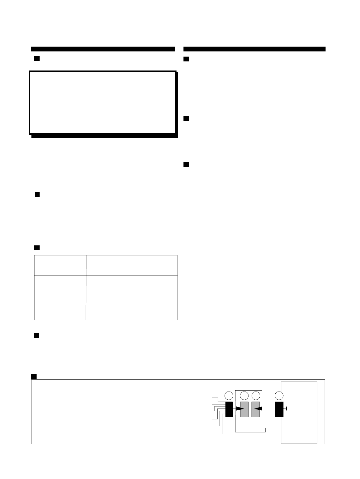
Interconnections
J0 Connector: T & B Ansley 609-1627 or equivalent
P0 Mating Connector: T & B Ansley 609-1630 or equivalent.
J3 Connector: T & B Ansley 609-2627 or equivalent.
P1 Connector: 3M 3399-7626 or equivalent
+5V opt.
+12V
VID
VCLK
HS
VS
P0 J3
DC/DC
Converter
J1J0 P3 P1
Display
Page 7

Display External Dimensions
7 EL4836LP, EL4836LP-ICE
DC/DC Converter - PS512-1
Page 8

8EL4836LP, EL4836LP-ICE
Description of Warranty
This description is not the full warranty, and should
not be construed as a substitute for the full warranty.
A copy of the full warranty is available upon request.
Planar warrants that the goods it sells will be free of
defects in materials and workmanship, and that these
goods will substantially conform to the specifications
furnished by Planar, and to any drawings or specifications furnished to the Seller by the Buyer if approved
by the Seller. This warranty is effective only if Planar
receives notice of such defect or nonconformance
during the period of warranty, which begins the day of
delivery.
The goods Planar sells are warranted for a period
of one year unless otherwise agreed to by Planar and
the Buyer. The Buyer must return the defective or nonconforming goods, upon request, to Planar not later
than 30 days after Planar’s receipt of notice of the
alleged defect or non-compliance. Buyer shall prepay
transportation charges, and Planar shall pay for return
of the goods to the Buyer. No goods are to be returned
to Planar without prior written permission.
Easy to Use
There are many options available which make
Planar flat panel displays easy to use, easy to interface,
and easy to package. Call Planar for complete
information.
Support and Service
Planar is a U.S. company based in Beaverton, Oregon and Espoo, Finland with a world-wide sales
distribution network. Full application engineering
support and service are available to make the integration of Planar displays as simple and quick as possible
for our customers.
RMA Procedure: For a Returned Material Authorization number, please contact Planar Systems, Inc., or
Planar International's Customer Service Department,
with the model number(s) and original purchase order
number(s). When returning goods for repair, please
include a brief description of the problem, and mark
the outside of the shipping container with the RMA
number.
The warranty does not apply in cases of improper
or inadequate maintenance by the Buyer, unauthorized modification of the goods, operation of the goods
outside their environmental specifications, neglect or
abuse of the goods, or modification or integration with
other goods not covered by a Planar warranty when
such modification or integration increases the likelihood of damage of the goods.
Represented by:
Registered Trademarks
Planar and The Definition of Quality are registered
trademarks of Planar Systems, Inc.
Ordering Information
EL4836LP EL display with separate DC/DC
converter & interconnecting
cable.
EL4836LP-ICE ICETM display with seperate DC/
DC converter & interconnecting
cable.
Design and specifications subject to change without
notice.
North and South American sales: European and Far East sales:
Planar America, Inc. Planar International Ltd.
1400 NW Compton Drive P.O. Box 46 (Olarinluoma 9)
Beaverton, Oregon 97006-1992 FIN-02201 Espoo, Finland
Phone: (503) 690-1100 Phone: 358 0 420 01
Fax: (503) 690-1244 Fax: 358 0 422 143
10-94 020-0121-00 Copyright 1994 © Planar Systems, Inc. All rights reserved.
The Definition of Quality ®
®
 Loading...