

Page 1
EL480.60.43
ICEBRITE
TM
EL DISPLAY
Operations Manual
The Definition of Quality
®
Page 2

Copyright © 1999 by Planar Systems, Inc.
Planar and The Definition of Quality are registered trademarks. ICE and ICEBrite are
trademarks of Planar Systems, Inc.
This document is subject to change without notice. Planar provides this information as reference
only and does not imply any recommendation or endorsement of other vendor’s products.
Revision Control
Date Description
May 1999 Document number OM305-00
Page 3

Contents
EL480.60.43 Display ...........................................................................................................2
Features ............................................................................................................................2
Installation and Handling.....................................................................................................3
Mounting EL Displays .....................................................................................................3
Cable Length ....................................................................................................................3
Cleaning............................................................................................................................4
Avoiding Burn-In .............................................................................................................4
Specifications.......................................................................................................................4
Power................................................................................................................................4
Connector .........................................................................................................................5
Interface Information........................................................................................................6
Video Input Signals.......................................................................................................6
Dimming...........................................................................................................................7
Self-Test Mode.................................................................................................................8
Optical..............................................................................................................................8
Generating Grayscales......................................................................................................8
Environmental..................................................................................................................9
Reliability.........................................................................................................................9
Safety and EMI Performance ...........................................................................................9
Mechanical Characteristics.............................................................................................10
Component Envelope.....................................................................................................10
Figures
Figure 1. Data/Power Connector......................................................................................5
Figure 2. Video Input Timing Diagram............................................................................6
Figure 3. Pixel Location versus Sequence of Data...........................................................7
Figure 5. Display Dimensions........................................................................................11
Tables
Table 1. DC Input Voltage Requirements........................................................................4
Table 2. Video Input Requirements..................................................................................5
Table 3. Connector Pinouts..............................................................................................5
Table 4. Video Input Descriptions....................................................................................7
Table 5. Optical Characteristics. ......................................................................................8
Table 6. Environmental Characteristics. ..........................................................................9
Page 4

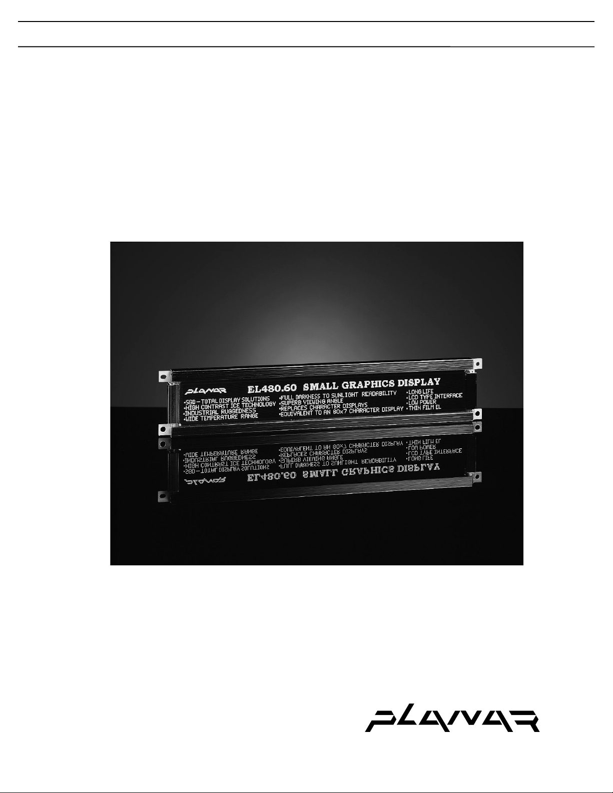
EL480.60.43 Display
The EL480.60.43 thin film electroluminescent (EL) small graphics
display is a low cost, high performance alternative to industry-standard
small graphics LCDs. The EL480.60.43 utilizes Planar’s proprietary
Integral Contrast Enhancement (ICE) technology to achieve
unparalleled image quality without the use of expensive filters. This
small graphics display excels in a wide range of ambient lighting
environments while effectively eliminating the blooming common to
other high-bright displays.
The display consists of an EL glass panel and control electronics
connected using elastomeric interconnects into a space-saving, rugged
package for easy mounting and includes a DC/DC converter. The
EL480.60.43 is easily interfaced using standard 4-bit LCD control
signals. Each of the pixels has an aspect ratio of 1:1 (V:H) and is
individually addressable to clearly display high information content
graphics and text.
Features
♦ Excellent visual performance:
High brightness and contrast
Wide viewing angle > 160°
No compensation needed
♦ Rapid display response < 1 ms
♦ Space-efficient mechanical package
♦ Low EMI emissions
♦ Extremely rugged and durable
♦ Reliable, long operating life with > 50,000 MTBF
♦ 4-bit STN LCD-type interface
EL480.60.43 Operations Manual (OM305-00)2
Page 5

Installation and Handling
Do not drop, bend or flex the display. Do not allow objects to strike the surface
of the display.
CAUTION: The display uses CMOS and power MOSFET devices. These
components are electrostatic-sensitive. Unpack, assemble, and examine
this assembly in a static-controlled area only. When shipping, use
packing materials designed for protection of electrostatic-sensitive
components.
CAUTION: To prevent injury in the event of glass breakage, the use of an
impact resistant shield or a protective overlay should be used on the
viewer side of the display.
Mounting EL Displays
Properly mounted, EL displays can withstand high shock loads as well as severe
vibration found in demanding applications. However the glass panel used in an
EL display will break if subjected to bending stresses, high impact, or excessive
loads.
Stresses are often introduced when a display is mounted into a product. Ideally,
the mounting tabs of the display should be the only point of contact with the
system. Use a spacer or boss for support; failure to do so will bend the display
and cause the glass to break. The instrument enclosure or frame should not flex
or distort in such a way that during use the bending loads might be transferred to
the display. Mounting surfaces should be flat to within ±0.6 mm (±.025"). Use
all the mounting holes provided. Failure to do so will impair the shock and
vibration resistance of the final installation.
The EL480.60.43 is a tab mounted display. Use appropriate length standoffs to
assure that screws through the mounting tabs do not introduce bending stresses
into the display. Do not deflect the ECB out of its normal plane. The
EL480.60.43 mounting tabs were designed for a 3 mm screw.
WARNING: These products generate voltages capable of causing
personal injury (high voltage up to 230 VAC ). Do not touch the display
electronics during operation.
Cable Length
A maximum cable length of 600 mm (24 in.) is recommended. Longer cables
may cause data transfer problems between the data transmitted and the display
input connector. Excessive cable lengths can pick up unwanted EMI. There are
third party products which allow this maximum cable length to be exceeded.
Contact Planar Application Engineering for more information.
EL480.60.43 Operations Manual (OM305-00) 3
Page 6

Cleaning
As with any glass or coated surface, care should be taken to minimize scratching.
Clean the display glass with mild, water-based detergents only. Apply the
cleaner sparingly to a soft cloth, then wipe the display. Disposable cleaning
cloths are recommended to minimize the risk of inadvertently scratching the
display with particles embedded in a re-used cloth. Particular care should be
taken when cleaning displays with anti-glare or anti-reflective films.
Avoiding Burn-In
As with other light emitting displays, displaying fixed patterns on the screen can
cause burn-in, where luminance variations can be noticed. Use a screen saver or
image inversion to avoid causing burn-in on the display.
Specifications
The EL panel is a matrix structure with column and row electrodes arranged in
an X-Y formation. Light is emitted when an AC voltage of sufficient amplitude
is applied at a row-column intersection. The display operation is based on the
symmetric, line-at-a-time data addressing scheme.
Power
The supply voltages are shown in Table 1. All internal high voltages are
generated from the display supply voltage (VH). The logic supply voltage (VL)
should be present whenever video input signals or VH is applied. The minimum
and maximum specifications in this manual should be met, without exception, to
ensure the long-term reliability of the display.
Performance characteristics are guaranteed when measured at 25 °C with rated
input voltage unless otherwise specified. Planar does not recommend operation
of the display outside these specifications.
Table 1. DC Input Voltage Requirements.
Parameter Symbol Min Typ Max Absolute
Max
Input voltage (nom=12.0 V) V
12 V Input Current I
Input voltage (nom=5.0 V) V
5 V Input Current I
Power consumption @ 60 Hz --- 0.7 W* 2.2 W --- 3.0 W
Power consumption @ 360 Hz --- 3.0 W* 6.2 W --- 11.0 W
* Display in stand-by mode
CAUTION: Absolute maximum ratings are those values beyond which
damage to the device may occur.
H
Hmax
L
Lmax
8.0 V --- 18.0 V 20.0 V
--- --- 0.65 A ---
4.75 V --- 5.25 V 6.0 V
--- --- 0.10 A ---
EL480.60.43 Operations Manual (OM305-00)4
Page 7

Connector
Table 2. Video Input Requirements.
Description Symbol Min Max Units Notes
Absolute Max. Input Voltage VImax -0.5 VL +.5 V V
Video logic high voltage VIH 70% 100% V
L
5.0 V
L=
All input thresholds
are CMOS
Video logic low voltage VIL 0 20% V
L
Video logic input current IIL -10 +10 µA
Input capacitance CIN – 15 pF
There is no overcurrent protection on either the VH or VL inputs to protect
against catastrophic faults. Planar recommends the use of a series fuse on the 12
volt supply(VH). A general guideline is to rate the fuse at 1.8 to 2 times the
display maximum current rating.
The standard display has a single connector, 20-pin, 2 mm pitch. The display
uses the Samtec EHT-110-01-S-D-SM locking connector or an equivalent
connector matching the pinouts in Table 3. The mating connector is available
through Samtec as an IDC cable assembly (Series TCSD-10-S-XX.X-). Consult
your Samtec representative (1-800-SAMTEC9) for cable and connector options.
(Viewed from electronics side of display)
Key
Pin 1
(Viewed from top of connector)
Figure 1. Data/Power Connector.
Table 3. Connector Pinouts.
Pin Signal Description Pin Signal Description
1 V
H
+12 V Power 2 V
H
+12 V Power
3 SLFTST Selftest 4 LUMA
5 V
L
+5 V Power 6 GND Ground
7 VS Vertical Sync 8 GND Ground
9 HS Horizontal Sync 10 GND Ground
11 VCLK Video Clock 12 GND Ground
13 VID
15 VID
17 VID
19 VID
0
1
2
3
Video Data 14 GND Ground
Video Data 16 GND Ground
Video Data 18 GND Ground
Video Data 20 GND Ground
Key
Pin 1
Pin 2
EL480.60.43 Operations Manual (OM305-00) 5
Page 8

Interface Information
3
First Line VID Data
1
9
7
11
Planar EL Small Graphics Displays (SGD) incorporate an interface that is
similar to many LCD interfaces. This interface is supported by a variety of offthe shelf chip sets which take care of all display control functionality, freeing the
system processor for other tasks. Designers select the chip set that best suits their
particular architecture and price point. This 4-bit LCD-type video interface
provides a low cost, flexible method for controlling display brightness and power
consumption.
Video Input Signals
The end of the top line of a frame is marked by VS, vertical sync signal as shown
in Figure 2. The end of each row of data is marked by HS.
The VS signal may be independently set to a CMOS low level at any time for
longer than one frame period. During the time of VS inactivity the display will
be blank. Halting VS results in a standby condition which minimizes power
consumption.
Horizontal Timing
HS
VCLK
VID0-3
Vertical Timing
VS
HS
Pixels: w x y z
10
Second Line VID Data
4
5
Pixels: a b c d
2
6
8
Figure 2. Video Input Timing Diagram.
Timing is compatible with LCD graphics controllers such as the SMOS 1351
display controller.
EL480.60.43 Operations Manual (OM305-00)6
Page 9

Table 4. Video Input Descriptions.
EL Panel
(Front)
VID0
Num Description Symbol Min. Typ. Max. Units
1 HS high time tHSh 100 nsec
2 HS low time tHSl 120 tVCLK
3 HS to VCLK rise tHSsu 95 nsec
4 VID setup to VCLK tVIDsu 50 nsec
5 VID hold from VCLK tVIDhd 50 nsec
6 Video clock period tVCLK 140 nsec
VCLK rise, fall time tVCLKrf 10 15 nsec
7 VCLK low width tVCLKl 30 nsec
8 VCLK high width tVCLKh 30 nsec
9 VS high setup to HS high tVShsu 140 nsec
10 VS hold after HS tVShd 140 nsec
11 VS low setup to HS high tVSlsu 140 nsec
12 HS period tHS 46 µsec
VS period tVS 60 tHS
Frame Rate 50 360 Hz
Dimming
a b c d e f g h i j k l m n o p
VID3
VID2
VID1
a
b
c
d
e
f
g
h
i
j
k
l
m
n
o
p
w x y z
Row 1
w
x
y
z
Figure 3. Pixel Location versus Sequence of Data.
The dimming control circuitry on the display allows the user to adjust the
luminance from 5% to 100% of the maximum brightness.
To control the display luminance, connect a 100 K(ohm) variable logarithmic
potentiometer between ground and the dimming pin. The full resistance of 100
K(ohm) will result in 100% of the maximum luminance. Reducing the resistance
will reduce the luminance, with resistance of 0 K(ohm) yielding roughly 5% of
the maximum luminance.
Alternatively an external voltage or current-mode D/A converter may be used to
dim the display by sinking a maximum of 250 uA for maximum dimming from
EL480.60.43 Operations Manual (OM305-00) 7
Page 10

pin 4 to ground. When left open, the luminance will remain at the maximum
off
level.
Self-Test Mode
The display incorporates a self-test mode composed of a 1 x 2 checkerboard and
full-on pattern displayed at 360 Hz. Upon power up, the 1 x 2 pattern is
displayed for several seconds, then the full-on pattern is displayed continuously.
The self-test mode is entered by leaving the SELFTEST pin pulled high. For
normal operation the SELFTEST pin must be pulled to a logic low. If the
SELFTEST pin is pulled high during normal operation, the display will enter the
self-test mode.
Optical
Table 5. Optical Characteristics.
Luminance
Lon (areal), min
Lon (areal), typ
L
(areal), max
15.4 cd/m²
92.5 cd/m²
21 cd/m²
125 cd/m²
0.17 cd/m²
@ 60 Hz, screen center
@ 360 Hz, screen center
@ 60 Hz, screen center
@ 360 Hz, screen center
3 points: all pixels off, 25 °C, 360 Hz
Non-uniformity
All pixels fully lit 26% Maximum difference two of three points, using the
Luminance Variation (Temperature)
Maximum
Luminance Variation (Time)
Maximum < 20%
Pattern Shadowing
Viewing Angle
Minimum
Contrast Ratio (Typical)
Generating Grayscales
formula:
LNU%=[1- (min_lum/max_lum)] x 100
± 25%
< 20% Across all refresh rates
>160°
32:1
158:1
11:1
Across operating temperature range
10,000 hours at 25 °C ambient
60 Hz frame rate @ 500 lux ambient
360 Hz frame rate @ 500 lux ambient
360 Hz frame rate @ 10,000 lux ambient
The EL480.60.43 is a monochrome display but will display dithered gray scale
when driven by a suitably equipped video controller.
EL480.60.43 Operations Manual (OM305-00)8
Page 11

Environmental
Table 6. Environmental Characteristics.
Temperature
Humidity
Non-condensing to 93% RH max @40 ºC,
Condensing to 95% RH max @25-55 °C,
Altitude
Tested per IEC 68-2-13
Operating/non-operating
Vibration
Random
Operating/non-operating
Shock
Operating/non-operating 100 g, 6 ms duration, half sine wave per IEC 68-2-27
* Refer to Table 7. Frame Rate vs. Temperature below
Operating Non-operating
-40 °C to +85 °C* -55 °C to +105 °C
per IEC 68-2-3
per IEC 68-2-30
0 to 58,000 ft (84kPa to 8kPa)
0.02g2/Hz, 5-500 Hz, 30 minutes on
each axis, per IEC 68-2-34
Table 7. Frame Rate vs. Temperature.
Display Ambient
Temperature
85 °C
65 °C 360 Hz
Reliability
The display MTBF is demonstrated to be greater than 50,000 hours at 360 Hz
with a 90% confidence level at 25 °C.
Safety and EMI Performance
The display is capable of operating in a final product that complies with FCC
Part 15 (Subpart J, Class B), EN55022 (Level B), and IEC801-2 when housed in
a suitable enclosure.
The display is a recognized component under UL1950 by Underwriters
Laboratories. The display will not inhibit the end product from complying with
EN60950, 1992 A1, A2, 1993 A3, or CSA 22.2 #950-95.
Maximum Frame Rate
240 Hz
EL480.60.43 Operations Manual (OM305-00) 9
Page 12

Mechanical Characteristics
Display External Dimensions
millimeters (inches) Width 236.0 (9.17) nominal
Height 45.2 (1.81) nominal
Depth 21.0 (1.25) nominal
Weight
Fill Factor
Display Active Area
millimeters (inches)
Pixel Size
millimeters (inches)
Pixel Pitch
millimeters (inches)
Component Envelope
The component envelope shown in Figure 4 illustrates the distance components
extend behind the display. Tall components do not necessarily fill this area.
Planar reserves the right to relocate components within the constraints of the
component envelope without prior customer notification. For this reason, Planar
advises users to design enclosure components to be outside the component
envelope.
An air gap of at least 5 mm is recommended to dissipate heat from display
components. Device designers will need to consider their specific system
requirements to determine the necessary spacing.
147 g (5.185 oz), nominal
49.8%
Width 203.88 (8.03) nominal
Height 25.38 (0.99) nominal
Width 0.30 (0.0118) nominal
Height 0.30 (0.0118) nominal
Horizontal .425 (0.0167) nominal
Vertical .425 (0.0167) nominal
EL480.60.43 Operations Manual (OM305-00)10
Page 13

Dimensions in are millimeters; inches in brackets.
Tolerances unless specified
.x ±0.50 [0.02]
.xx ±0.25 [0.01]
Figure 4. Display Dimensions.
Note: This is not a controlled version of the mechanical drawing. Prior to beginning your
design, please contact Planar Applications Engineering for the current detailed drawing.
EL480.60.43 Operations Manual (OM305-00) 11
Page 14

Page 15

Description of Warranty
This description is not the full warranty, and should not be construed as a substitute for the full
warranty. A copy of the full warranty is available upon request.
Planar warrants that the goods it sells will be free of defects in materials and workmanship, and that
these goods will substantially conform to the specifications furnished by Planar, and to any drawings or
specifications furnished to the Seller by the Buyer if approved by the Seller. This warranty is effective
only if Planar receives notice of such defect or non-conformance during the period of warranty, which
begins the day of delivery.
The goods Planar sells are warranted for a period of one year unless otherwise agreed to by Planar and
the Buyer. The Buyer must return the defective or non-conforming goods, upon request, to Planar not
later than 30 days after Planar’s receipt of notice of the alleged defect or non-compliance. Buyer shall
prepay transportation charges, and Planar shall pay for return of the goods to the Buyer. No goods are
to be returned to Planar without prior permission.
The warranty does not apply in cases of improper or inadequate maintenance by the Buyer,
unauthorized modification of the goods, operation of the goods outside their environmental
specifications, neglect or abuse of the goods, or modification or integration with other goods not
covered by a Planar warranty when such modification or integration increases the likelihood of damage
of the goods.
Ordering Information
Product Part Number Features
EL480.60.43 996-0265-01 Standard version
EL480.60.43 CC 996-0265-02 EL480.60.43 with conformal coating
Design and specifications are subject to change without notice.
Planar Systems continues to provide optional, and in many cases custom, features to address the
specific customer requirements. Consult Planar Sales for pricing, lead time and minimum quantity
requirements.
Support and Service
Planar is a U.S. company based in Beaverton, Oregon and Espoo, Finland, with a world-wide sales
distribution network. Full application engineering support and service are available to make the
integration of Planar displays as simple and quick as possible for our customers.
RMA Procedure: For a Returned Material Authorization number, please contact Planar Systems, Inc.
with the model number(s) and serial number(s). When returning goods for repair, please include a brief
description of the problem, and mark the outside of the shipping container with the RMA number.
Page 16

North & South America OEM Sales Europe & Asia-Pacific OEM Sales
Planar Systems, Inc.
1400 NW Compton Drive
Beaverton, OR 97006-1992
Tel. +1 (503) 690-6967
Fax +1 (503) 690-1493
sales@planar.com
app_eng@planar.com
Planar Systems, Inc.
P.O. Box 46; Olarinluoma 9
FIN-02201 Espoo, Finland
Tel. +358 9 42 0010
Fax +358 9 4200 200
intlsales@planar.com
tech_support@planar.com
Visit the Planar web site: http://www.planar.com
OM305-00
 Loading...