

Page 1
EL320.240-FA3
Multi-Color QVGA EL Display
OPERATIONS MANUAL
www.planar.com
Page 2
Revision Control
Date Description
February 2007 Initial release, 020-0591-00 Rev A
EL320.240-FA3 Operations Manual Page 2 of 25
Page 3

Table of Contents
EL320.240-FA3 Multi-Color QVGA Display………………………………...…………...…4
Features and Benefits…………………………………………………………………….…4
Installation and Set-up…………………………………………………………...………..5
Mounting Considerations…………………………...………...…..…………………………5
Cable Length…………………………………………………...……………………………5
Cleaning………………………………………………………...……………………………5
Avoiding Image Burn-in………………………………………..……………………………6
Power Supply and Video Sequencing………...…………...……...…………………………6
VH Overcurrent Protection……………...……………………...……………………………6
Internal Frame Buffer…………………………………...………………...………….………6
Color Bit Mapping……................………………………...………………...………….………6
Display Overlay Considerations……...............……………...……………...………….………7
Specifications and Operation………………………...……………………………..……..8
Environmental……………………………………………...……………………………...…8
Over-temp Condition………………………………………...…...…………………...…8
Optical……………………………………………...…………………………………...….…9
Displayed Colors……………………………………………...……………….…………9
Power…………………………………...…………………………………………………...10
Display Interface……………………..………………...……………………………..……..11
Video Mode Selection…………………………………...……………………………..11
Connector…………………………………...………………………………...………...12
Display Input Descriptions…………………………………...……………….………...13
Video Mode Timing ………………………………………...………………...……...…14
Dimming…………………………………...……………………………………………….19
Self Test Mode…………………………………...……………………………………….....20
Reliability………………………………………...…………………………………...…...…21
Safety and EMI Performance…………………………………...……………………...……21
Mechanical Characteristics…………………………………...……………………...……...21
Display Dimensions and Component Envelope …………………………………...…22
Warranty…………….…………………………………………………………….…...…23
Ordering Information…………………………………………………………..……...…23
RoHS……………………………………...……………………………………….…...….24
Support and Service…………………………………………………….………..……....24
EL320.240-FA3 Operations Manual Page 3 of 25
Page 4
EL320.240-FA3 Multi-Color QVGA Display
The EL320.240-FA3 thin film electroluminescent (EL) multi-color display is a
high-performance alternative to QVGA (320 x 240) LCDs and is the ideal
solution in demanding applications where superior visual performance,
extreme temperature range, and environmental ruggedness are critical.
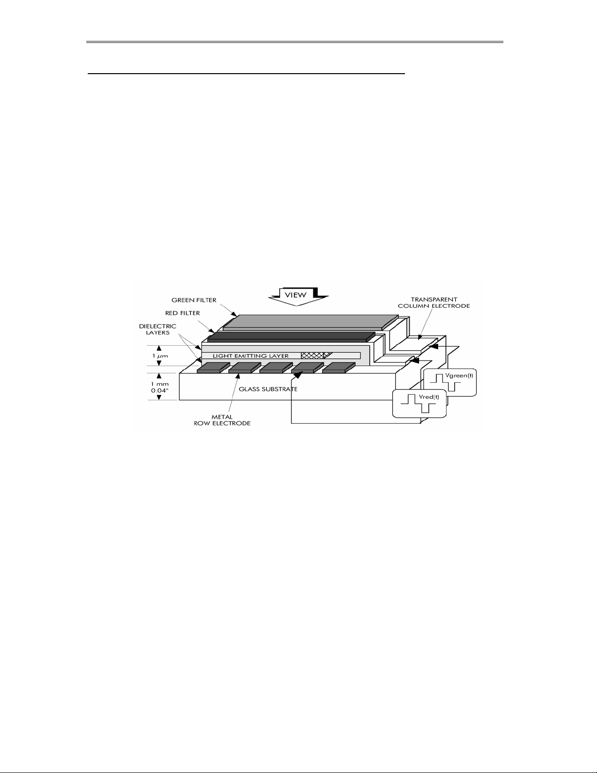
The EL320.240-FA3 utilizes Planar’s proprietary Integral Contrast Enhancement
technology combined with red and green filters patterned over Planar’s
industry-leading yellow phosphor to achieve unparalleled image quality in
hues of red, green and yellow. Three intensity levels in each of the red and
green sub-pixels generate sixteen distinct colors (nine chromatically different
colors, black, and two mid-levels of red, green, and yellow.)
The display consists of a solid state EL glass panel, depicted below, with
a124mm diagonal active area, and control electronics assembled into a
space-saving, rugged package for easy mounting.
Features and Benefits
• Excellent visual performance:
Unparalleled crisp, clear image
Excellent contrast
Unbeatable viewing angle of > 160° for all colors in all directions
No off-axis color or contrast shift
• Extremely wide operation temperature range: -50 to 85C
• Instant turn on at -50C: no heaters needed, no warm up time
• Long life phosphor: allows >11 years of continuous operation
• Wide dimming range via digital control and analog voltage input
• Rugged solid state construction
• Great reliability: MTBF > 50,000 hours demonstrated
• Low cost of ownership: no maintenance, no lamps to replace
• AMLCD-type panel interface, 3V and 5V logic compatible
• RoHS compliance
EL320.240-FA3 Operations Manual Page 4 of 25
Page 5

Installation and Set-up
Do not drop, bend, or flex the display. Do not allow objects to strike the
surface of the display.
CAUTION: The display uses CMOS and devices. These components are
electrostatic-sensitive. Unpack, assemble, and examine this assembly in a
static-controlled area only. When shipping, use packing materials designed
for protection of electrostatic-sensitive components.
Mounting EL Displays
Properly mounted, EL displays can withstand high shock loads as well as
severe vibration found in demanding applications. However the glass panel
used in an EL display will break if subjected to bending stresses, high impact,
or excessive loads.
Avoid bending the display. Stresses are often introduced when a display is
mounted into a product. Ideally, the mounting tabs of the display should be
the only point of contact with the system. Use a spacer or boss for support;
failure to do so will bend the display and cause the glass to break. The
instrument enclosure or frame should not flex or distort in such a way that
during use the bending loads might be transferred to the display. The
EL320.240-FA3 mounting tabs were designed for a 3 mm screw. Mounting
surfaces should be flat to within ±0.6 mm (±0.025"). Use all the mounting holes
provided. Failure to do so will impair the shock and vibration resistance of the
final installation.
WARNING: These products generate voltages capable of causing personal
injury (high voltage up to 140 Vac ). Do not touch the display electronics
during operation.
Cable Length
A cable length of 0.5 m (20 inches) or less is recommended. Longer cables may
cause visual artifacts such as pixel “jitter” due to data transfer problems
between the host and the display.
Cleaning
As with any glass surface, care should be taken to minimize scratching. Clean
the display glass with mild, water-based detergents only. Apply the cleaner
sparingly to a soft cloth, then wipe the display. Disposable cleaning cloths are
recommended to minimize the risk of inadvertently scratching the display
with particles embedded in a re-used cloth.
EL320.240-FA3 Operations Manual Page 5 of 25
Page 6

Avoiding Image Burn-In
As with other light emitting displays, displaying fixed patterns on the screen
may cause burn-in, where luminance variations can be noticed after hundreds
of hours of operation. To avoid image burn-in, use a screen saver or use
periodic image inversion if possible. Note that the rate of image burn-in will
slow over time such that most of the burned-in image effect occurs in the first
1000 hours of operation.
Power Supply and Video Sequencing
Any combination or sequencing in the application or removal of VH (12VDC
input power)and/or video signals will not result in abnormal display operation
or display failure
.
VH Overcurrent Protection
There is no overcurrent protection on VH, the 12V power input. To protect
against catastrophic faults, Planar recommends the use of a fuse or similar
protection on the VH input to the display.
Internal Frame Buffer
This display includes an internal frame buffer, which is required to transform
the incoming video data into the desired displayed data. The display frame
rate (the rate at which the phosphor is scanned) and thus the display
brightness are independent of the frame rate of the user-supplied input data.
Video data need not be continuously sent to the display since previously sent
data is stored indefinitely until new data is received.
CAUTION: Some third-party video controllers use frame dithering algorithms
to produce gray scale images. If such algorithms are used, the internal frame
buffer may cause objectionable visual artifacts.
Color Bit Mapping
The EL320.240-FA3 utilizes standard AMLCD-type video interface timing. Thus
it is possible that a video source will be chosen which provides 18 bits of data
per pixel (six bits each for red, green, and blue) as is common for AMLCD
displays. Because the EL320.240-FA3 requires just 4 bits (two each for red and
green), the 18 bits would need to be mapped into 4 bits.
One option is to use just the two most significant bits of red and green and
leave the rest open or terminated. This is the easiest approach and will work
well if the user is developing their own content and can refrain from using
patterns containing dim colors since these would likely be displayed as black.
EL320.240-FA3 Operations Manual Page 6 of 25
Page 7

Another option is to electrically “OR” the 3 red MSBs together and route the
result to R1, OR the 3 red LSBs together and route to R0, and do the same for
G1 and G0. Additionally the bits of blue could be OR’d together with either
the red or green bits depending on the characteristics of the images that need
to be displayed.
If upgrading from a monochrome EL320.240 display model and using the SGD
timing mode, some engineering will be required to map the monochrome
SGD data into the color data required by the EL320.240-FA3. SGD data is one
bit per pixel, and 4 pixels of data are latched per video clock edge. The
EL320.240-FA3 is 4 bits per pixel with one pixel of data latched per clock edge.
Display Overlay Considerations
Though not a requirement, often the end system will employ some type of
transparent cover over the front the display. The purpose and construction of
the cover varies depending on the application and economical constraints.
The cover may be used to improve contrast under certain lighting conditions
by reducing reflections, to provide additional impact protection, to provide a
more seamless enclosure appearance, or to protect against fluids. See
Application Note AN117-01 at planar.com for details. Some leading suppliers
of various display overlays are: EyeSaver International, Cyro Industries, and
Dontech Incorporated.
EL320.240-FA3 Operations Manual Page 7 of 25
Page 8

Specifications and Operation
Environmental
Environmental Characteristics
Temperature
Operating -50°C to +85°C
Storage -50°C to +105°C
Humidity
Non-condensing,
operating
Condensing,
non-operating
Altitude
Operating/non-operating 0 to 18 km (58k ft) per IEC 68-2-13
Vibration
Random
Operating/non-operating
93% RH max at +40°C, per IEC 68-2-3
95% RH max at +55°C, per IEC 68-2-30
0.05 g2/Hz, ASD level, 5-500 Hz
per IEC 68-2-36, test Fdb.
Shock
Operating/non-operating 100 g, 6 ms, half sine wave on each of six surfaces per
Over-temp Condition
The display contains a temperature sensor which measures the temperature of the circuit board at the lower left corner as viewed from the component side of the board.
If the board temperature exceeds approximately 100C, the display will
automatically operate at its lowest luminance setting (as if LUM0 was low and LUM1
was high) to reduce the board temperature. At no point will the display be shut
down. The content of the pattern will be unaffected.
After surpassing 100C, once the board temperature drops below approximately 92C
or the power is cycled, the display will resume normal operation as defined by the
LUM0 and LUM1 settings. Typically, the 100C limit may be reached if the 12V input
power exceeds 6W when the ambient temperature for the display electronics is
85C.
IEC 68-2-27, test Ea.
EL320.240-FA3 Operations Manual Page 8 of 25
Page 9

Optical
Optical Characteristics
Luminance
Guaranteed
Typical
Guaranteed
Typical
Black luminance
Luminance Non-uniformity
Typical 5% Maximum difference two of five points (center plus
Luminance Variation across Temperature
Maximum
Luminance Decrease over Time
Typical 6% 10,000 hours
Typical 15% 100,000 hours (> 11 years)
Viewing Angle
Minimum
>75 cd/m²
95 cd/m²
>41 cd/m²
53 cd/m²
<0.2 cd/m²
±15%
>160° in all directions; no change to contrast, color, or luminance
max frame rate (LUM0=LUM1=0), yellow, center
max frame rate (LUM0=LUM1=0), yellow, center
min frame rate (LUM0=0, LUM1=1), yellow, center
min frame rate (LUM0=0, LUM1=1), yellow, center
max frame rate, 5 points: center plus four corners
four corners), using the formula:
BNU%=[1- (min_lum/max_lum)] x 100%
Deviation from 25°C to the operating extremes
Contrast Ratio (typical)
1000:1
Displayed Colors
The display is capable of displaying 16 hues based on the red and green sub-pixels
and frame dithering (utilizing a three frame period with either a 33% or 66% duty
cycle) generated by the display.
Color
Level
R1 R0 G1 G0 Pixel Color
0 0 0 0 0 Black n/a Off Off
1 0 0 0 1 Dim Green .450,.546 Off 1/3
2 0 0 1 0 Medium Green .450,.546 Off 2/3
3 0 0 1 1 Green .450,.546 Off On
4 0 1 0 0 Dim Red .606,.393 1/3 Off
5 0 1 0 1 Dim Yellow .497,.498 1/3 1/3
6 0 1 1 0 Greenish Yellow .481,.514 1/3 2/3
7 0 1 1 1 Reddish Green .471,.524 1/3 On
8 1 0 0 0 Medium Red .606,.393 2/3 Off
9 1 0 0 1 Reddish Yellow .524,.473 2/3 1/3
10 1 0 1 0 Medium Yellow .497,.498 2/3 2/3
11 1 0 1 1 Yellowish Green .486,.509 2/3 On
12 1 1 0 0 Red .606,.393 On Off
13 1 1 0 1 Greenish Red .535,.462 On 1/3
14 1 1 1 0 Yellowish Red .511,.485 On 2/3
15 1 1 1 1 Yellow .497,.498 On On
2.5:1
1.5:1
Description
@ 0 lux ambient (dark room), maximum frame rate
@ 20k lux ambient (daylight), maximum frame rate
@ 75k lux ambient (direct sun), maximum frame rate
Typical Chromaticity
(x, y coordinates)
FA1 Red
Intensity
FA1 Green
Intensity
EL320.240-FA3 Operations Manual Page 9 of 25
Page 10

Power
The supply voltage and power requirements are shown in the table below. The
power will vary greatly depending on the number of pixels lit and depending
on the chosen luminance level (see graph below.) Power levels will vary up to
+/-15 % from display to display due to brightness variation.
DC Input Voltage and Power Requirements
Parameter Minimum Typical Maximum Abs Max
Display supply voltage, VH 8 V 12 V 18V
Supply current at +12 V 0.45 A 0.95 A 1.09 A
Power consumption @ maximum
luminance (LUM0=LUM1=0)
Power consumption @ minimum
luminance (LUM0=0, LUM1 =1)
Quiescent power consumption
(SHUTDOWN = 1)
Note: 1) Maximum power: 90% of pixels lit (yellow) per row
2) Abs Max power: 90% of pixels lit (yellow) per row, worst case display sample
2) Typical power: pattern with 10% of pixels lit per row, typical display
3) All power numbers are for LUMA open (no analog dimming)
5.4 W 11.4 W 13.1 W
3.5W 6.9 W
0.5 W
EL320.240-FA 3 Power vs. Percent of Pi xel s O n, for A ll Three
Lumi n anc e Settings , Typical
12
10
8
6
4
Power Consumption, watts
2
0
0 20406080100
Pe rcenta ge of pixels turne d on (yell ow) per row
Max l um inance, 325 Hz
Med lum i nanc e, 240 Hz
Min l um inance, 180 Hz
EL320.240-FA3 Operations Manual Page 10 of 25
Page 11

Display Interface
The display supports five video interface modes: SGD timing as used on the
Planar EL320.240.36-HB (though with video data differences to denote colors)
and the four AMLCD timing modes used on Sharp and Kyocera QVGA color
displays (though using only two bits of red and green data). Four bits of data
per pixel are provided. The data is clocked to the display with a video clock,
VCLK. Frame and line synchronization is provided by the VS, HS and (if needed)
DE signals.
Video mode detection is performed automatically. The display evaluates the
timing of the incoming video approximately every 25 msec and will shift “on
the fly” between video modes as required.
The internal display controller utilizes a frame buffer to provide the display
with the appropriate modulation on a line by line and frame by frame basis to
implement the color generation, including frame dithering algorithms. Thus
the input frame rate and the display scan rate, in general, will not be the same
and will not be synchronous.
Video Mode Selection
Inputs LUM0 and LUM1 must be set to attain the desired video mode as shown
in the following table.
LUM0 and
LUM1 = 1?
No 0 Active AMLCD,Q
No 0 0 AMLCD,
No 1 Active AMLCD,
No 1 0 AMLCD,
No X 1 SGD SGD timing. Horizontal start of valid data is
Yes X X Self test Displays various patterns at the maximum
V/Q
Input
DE
Input
Mode
Name
VGA
QVGA,
Fixed
VGA
VGA,
Fixed
Mode Description
(refer to Video Mode Timing for details)
AMLCD timing. DE determines the
horizontal location of data.
AMLCD timing. Horizontal start of valid
data is a predetermined number of VCLKs
from HS.
AMLCD timing. Displays upper left
quadrant of a VGA (640x480) input signal
with DE determining the horizontal
location of data.
AMLCD timing. Displays upper left
quadrant of a VGA (640x480) input signal
with the horizontal start of valid data
predetermined.
the first VCLK after HS.
refresh rate regardless of video input data.
Useful for verifying display functionality.
Note:1) DE is considered active if more than eight logic transitions are detected
2) SGD mode is similar to that of the Planar EL320.240.36 and EL320.240-HB
displays but with required changes to the video data content to represent color
3) The AMLCD modes are compatible with those found on the following QVGA
displays though the video data content of 4 bits/pixel is a subset of the typical
18 bits/pixel: Sharp LQ057Q3DC12, Sharp LQ057Q3DC02, Kyocera
TCG057QV1AC
EL320.240-FA3 Operations Manual Page 11 of 25
Page 12

Connector
K
The display uses the Samtec EHT-110-01-S-D or equivalent 2mm locking
connector. The mating connector is in the Samtec TCSD family of cable strips.
The proper connector, user-specified cable length and connector
configuration is supplied as a single unit. Consult your Samtec representative
(1-800-SAMTEC9) for the cable/connector options. Compatibility with nonSamtec equivalents should be verified before use.
Pin 19
(Viewed from
back of display)
Pin 1
J1
ey
Pin 1
Pin 2
(Viewed from top of connector)
Figure: Data/Power Connector
J1 Connector Pin Assignment
Signal Pin Pin Signal
VH 1 2 VH
V/Q 3 4 DE
LUMA 5 6 LUM0
VS 7 8 LUM1
HS 9 10 GND
VCLK 11 12 GND
R0 13 14 GND
R1 15 16 GND
G0 17 18 GND
G1 19 20 SHUTDOWN
EL320.240-FA3 Operations Manual Page 12 of 25
Page 13

Display Input Descriptions
y
y
p
y
Signal Description
VH Power supply voltage for display functions. 12 VDC nominal.
V/Q Format selection: in AMLCD timing modes, selects between VGA mode (high) and
QVGA mode. In VGA mode the upper left quadrant of data will be displayed.
Internall
DE Data Enable: in AMLCD non-fixed timing modes, the rising edge identifies the data
for the first pixel of each row and must stay high until the data for the last pixel of
each row is clocked. DE is also used to determine the video timing mode.
Internally pulled high to 3.3V.
LUMA Analog Luminance Control: used to reduce the display luminance by reducing the
voltage applied to the display phosphor. If left open, defaults to the luminance set
b
LUM0, LUM1 Digital Luminance Controls: used to reduce the luminance of the display by
reducing the frequency at which the display is scanned.
VS Vertical Sync: identifies the start of each frame (entire screen) of data. Internally
ulled low.
HS Horizontal Sync: identifies the start of each horizontal row of data.
VCLK Video Clock: the falling edge latches the video data (R0, R1, G0, and G1)
R0 Video data: Least significant bit for red sub-pixel
R1 Video data: Most significant bit for red sub-pixel
G0 Video data: Least significant bit for green sub-pixel
G1 Video data: Most significant bit for green sub-pixel
SHUTDOWN Display Shutdown: when high, will disable the display, thus rendering the display
black and minimizing power. All display data will be stored but no new data
accepted when SHUTDOWN is high. Internall
GND Signal return for power and logic
pulled low.
LUM0 and LUM1.
pulled low.
Display Input Signal Requirements
Description Min Max Units Notes
Input Voltage Range -0.3 5.5 V
Video logic high voltage 2.0 5.0 V All input thresholds are TTL
Video logic low voltage 0 0.8 V
LUMA input voltage 0 5.5 V
LUMA input current –250 0 uA
Note: 1. All inputs (except LUMA input) are 5V tolerant, with 270 ohm series resistors.
2. Input capacitance for all inputs except LUMA is 8 pF typical.
3. DE, LUM0, and LUM1 have > 20kohm pull-up resistors to 3.3V.
4. VS, SHUTDOWN, and V/Q have > 20kohm pull-down resistors to ground
EL320.240-FA3 Operations Manual Page 13 of 25
Page 14

EL320.240-FA3 Operations Manual Page 14 of 25
Page 15

Video Mode Timing—SGD Video Mode
0
K
a
l
g
Item Description Min. Max. Units
1 HS high time 30 nsec
2 Last VCLK fall to HS fall 20 nsec
3 HS to VCLK rising edge 10 nsec
4 R/G data setup to VCLK 10 nsec
5 R/G data hold from VCLK 10 nsec
6 VCLK period 100 nsec
7 VCLK low width 30 nsec
8 VCLK high width 30 nsec
9 VS high setup to HS low 140 nsec
10 VS hold after HS 140 nsec
11 VS low setup to HS high 140 nsec
12 HS period 34 usec
VS period 240 HS periods
VS frequency 120 Hz
Notes: 1) The first HS falling edge occurring when VS is high indicates the first row
2) The video data for a given row is clocked in prior to the falling edge of HS
3) The first 320 VCLK falling edges after the fall of HS clock in the valid data
4) If video inputs are halted, the previously clocked in data will be displayed
5) Video frame dithering/gray scale may cause artifacts due to the frame buffer
6) All timing measurements are made at 1.6V
Horizontal Tim ing
HS
VCL
R/G dat
Vertical Tim in
VS
HS
2
3
4 5
7
6
8
Da ta f o r F irst P ix e l
10
9
1
11
1
First Line of
Data
Pixe
EL320.240-FA3 Operations Manual Page 15 of 25
Second Line of Pixel Data
Page 16

Video Mode Timing—AMLCD Video Mode, QVGA
K
a
g
4
Item Description Min. Max. Units
1 HS low time 2 200 VCLK periods
2 HS to VCLK phase difference 10 VCLK period - 10 nsec
3 HS to DE phase difference 2 HS period - 340 VCLK periods
4 DE set up time 5 VCLK period - 10 nsec
5 VCLK frequency 7 MHz
6 R/G data set up to VCLK 5 nsec
7 R/G data hold from VCLK 10 nsec
8 VS low width 2 34 HS periods
9 VS to HS phase difference 0 HS period – HS low
10 Vertical start position After 7 HS rising edges
DE high time 2 HS period - 10 VCLK periods
HS period 50 usec
VS period 251 280 HS periods
H orizontal Tim ing
HS
VCL
R/G dat
time
1
2
horizontal invalid data period
nsec
5
6 7
DE
V ertical T im in
VS
HS
R/G data
3
da ta for first pix el
8
9
Line 1
Line 2
Line N
10
vertical invalid data period
data fo r first lin e
EL320.240-FA3 Operations Manual Page 16 of 25
Page 17

Video Mode Timing—AMLCD Video Mode, QVGA, Fixed
a
g
Item Description Min. Max. Units
1 HS low time 2 200 VCLK periods
2 HS to VCLK phase difference 10 VCLK period - 10 nsec
5 VCLK frequency 7 MHz
6 R/G data set up to VCLK 5 nsec
7 R/G data hold from VCLK 10 nsec
8 VS low width 2 34 HS periods
9 VS to HS phase difference 0 HS period – HS low
time
10 Vertical start position After 7 HS rising edges
HS period 50 usec
VS period 251 280 HS periods
Horizontal T iming
HS
VCLK
R/G dat
1
first v a lid c loc k =
2
clock edge C 1
clock edge C 52
horizontal invalid data period
nsec
5
6 7
Vertical Tim in
VS
HS
R/G data
da ta fo r firs t p ix el
8
9
Line 1
Line 2
Line N
10
ve rtic a l in va lid d ata p e rio d
da ta fo r firs t lin e
EL320.240-FA3 Operations Manual Page 17 of 25
Page 18

Video Mode Timing—AMLCD Video Mode, VGA
K
g
Item Description Min. Max. Units
1 HS low time 2 200 VCLK periods
2 HS to VCLK phase difference 10 VCLK period - 10 nsec
3 HS to DE phase difference 44 HS period - 664 VCLK periods
4 DE set up time 5 VCLK period - 10 nsec
5 VCLK frequency 28.33 MHz
6 R/G data set up to VCLK 5 nsec
7 R/G data hold from VCLK 10 nsec
8 VS low width 2 34 HS periods
9 VS to HS phase difference 0 HS period – HS low time nsec
10 Vertical start position After 34 HS rising edges
DE high time 2 HS period - 10 VCLK periods
HS period 30 usec
VS period 515 560 HS periods
Horizontal Tim ing
HS
VCL
R/G data
1
2
horizontal invalid data period
5
6 7
DE
Vertical Timin
VS
HS
R/G data
3
8
9
Line 1
vertical invalid data period
EL320.240-FA3 Operations Manual Page 18 of 25
Line 2
10
4
Line N
da ta fo r firs t pix e l
da ta fo r fir st lin e
Page 19

Video Mode Timing—AMLCD Video Mode, VGA, Fixed
a
g
Item Description Min. Max. Units
1 HS low time 2 200 VCLK periods
2 HS to VCLK phase
difference
5 VCLK frequency 28.33 MHz
6 R/G data set up to VCLK 5 nsec
7 R/G data hold from VCLK 10 nsec
8 VS low width 2 34 HS periods
9 VS to HS phase difference 0 HS period – HS low time nsec
10 Vertical start position After 34 HS rising edges
HS period 30 usec
VS period 515 560 HS periods
10 VCLK period - 10 nsec
H orizontal T im in g
HS
VCLK
R/G dat
Vertical Timin
VS
1
2
clock edge C1
horizontal invalid data period
8
9
first v a lid c loc k =
clock edge C 104
5
6 7
da ta fo r f irst p ix e l
HS
Line 1
Line 2
Line N
10
R/G data
vertical invalid data period
da ta fo r first lin e
EL320.240-FA3 Operations Manual Page 19 of 25
Page 20

Dimming
Dimming is used to reduce the display luminance to better match ambient
conditions or to reduce power consumption. There are two methods for
dimming the EL320.240-FA3 display.
The preferred method is digital dimming, where the internal display frame rate
is controlled using the LUM0 and LUM1 inputs. The internal frame rate is the
frequency at which the drive voltage is applied to the display phosphor and
thus impacts luminance and power consumption. Note that the internal
display frame rate is unrelated to the frame rate defined by the VS input.
(For normal operation, LUM0 and LUM1 must not be open or both high. When
LUM0 and LUM1 are high or open, the display enters self test mode where predetermined patterns are displayed. )
Using the combination of the two inputs LUM0 and LUM1, the following
display luminance settings are obtained:
Digital Luminance Control Characteristics
LUM0 logic level 0 1 0
LUM1 logic level 0 0 1
Approximate Frame Rate, Hz 325 240 180
Approximate Relative
Luminance
100% 74% 55%
If the dimming obtained from digital dimming is insufficient, analog
luminance control (the LUMA input) may be used to adjust the luminance
further downward. Connection of a 50 kohm variable resistor between LUMA
and GND will give a brightness range of approximately <5% to 100% of the full
luminance value (see dimming curve below). Alternatively, an external voltage
or D/A converter may be used to sink current from LUMA to GND.
Analog Luminance Control Characteristics
Max luminance, LUMA open 100% (no dimming)
Max luminance, 50kohm from
LUMA to GND
Min luminance, 0 ohm from
LUMA to GND
LUMA open circuit voltage 4 V, nominal
LUMA maximum sink current 250 uA
100%
0.2% typical,
5% maximum
When using LUMA for dimming, visual artifacts such as brightness nonuniformity and image burn-in may become more noticeable especially at low
dimming levels. To minimize the visual artifacts, analog dimming should be
employed with LUM0 and LUM1 set for the minimum frame rate. See the
following graph for the typical analog dimming response. Note that the actual
response will vary depending on individual display characteristics.
EL320.240-FA3 Operations Manual Page 20 of 25
Page 21

EL320. 24 0- FA3 Anal og Dimming Res ponse, Typical
120
100
80
60
40
20
Percentage of full lum i nance
0
01234
Self Test Mode
The display contains a self test mode composed of patterns displayed at the
maximum frame rate for approximately four seconds each. Self test mode can
be useful for verifying operation of the display.
The self test patterns are as follows: yellow diagonal lines with a one sub pixel
wide perimeter box, all pixels red, all pixels green, and all pixels yellow. Upon
power up when in self-test mode, the pattern sequences are repeated three
times and then the pattern remains in the all pixels yellow state. The self test
mode is entered by leaving LUM0 and LUM1 disconnected or logically high.
LUMA voltage, volts
EL320.240-FA3 Operations Manual Page 21 of 25
Page 22

Reliability
The display MTBF is to be greater than 50,000 hours at maximum luminance
and maximum input power with a 90% confidence level at 25°C.
Safety and EMI Performance
The display will not inhibit the end product from obtaining these certifications:
IEC 60101-1; UL60950; CSA 22.2 #950; FCC Part 15, Subpart J, Class B; EN55022
Class B.
Mechanical Characteristics
Mechanical Characteristics
Display External Dimensions
millimeters (inches)
Weight (typical)
Display Active Area
millimeters (inches)
Pixel Size
millimeters (inches)
Pixel Pitch
millimeters (inches)
width 150.3 (5.92)
height 104.8 (4.13)
depth 20.56 max (0.81)
198 g
width 99.15 (4.05)
height 74.36 (2.93)
diagonal 123.94 (4.88)
width 0.265 (0.010)
height 0.265 (0.010)
width 0.31 (0.012)
height 0.31 (0.012)
EL320.240-FA3 Operations Manual Page 22 of 25
Page 23

Display Dimensions and Component Envelope
The Figure below shows the display dimensions. For additional details the
Mechanical Outline drawing is available at www.planar.com.
Note the 20.56 mm component envelope. This is the depth required by the
display to ensure no interference with display board components, which are
up to 12.19 mm in height. While tall components are the minority, Planar
reserves the right to relocate components
component envelope without prior customer notification. For this reason,
Planar advises users to design enclosure components to be outside the
component envelope.
Device designers will need to consider their specific system requirements to
determine the spacing necessary to maintain the specified ambient temperature
for the display electronics.
Air flow and the thermal properties of surrounding components will impact the
required depth of the air gap. In addition, electrical spacing must be considered
to accommodate the high voltage (up to 200 VDC) present on the display
electronics.
Figure: Display Dimensions (millimeters, ±0.25 mm)
within
the constraints of the
EL320.240-FA3 Operations Manual Page 23 of 25
Page 24

Warranty
Seller warrants that the Goods will conform to published specifications and be free from defects in
material for 12 months from delivery.
Warranty repairs shall be warranted for the remainder of the original warranty period. Buyer shall
report defect claims in writing to Seller immediately upon discovery, and in any event, within the
warranty period. Buyer must return Goods to Seller within 30 days of Seller’s receipt of a warranty
claim notice and only after receiving a Returned Material Authorization number from the Seller.
Seller shall, at its sole option, repair or replace the Goods.
If Goods were repaired, altered or modified by persons other than Seller, this warranty is void.
Conditions resulting from normal wear and tear and Buyer's failure to properly store, install, operate,
handle or maintain the Goods are not within this warranty. Repair or replacement of Goods is
Seller’s sole obligation and Buyer's exclusive remedy for all claims of defects. If that remedy is
adjudicated insufficient, Seller shall refund Buyer's paid price for the Goods and have no other
liability to Buyer.
All warranty repairs must be performed at Seller’s authorized service center using parts approved by
Seller. Buyer shall pay costs of sending Goods to Seller on a warranty claim and Seller shall pay costs
of returning Goods to Buyer. The turnaround time on repairs will usually be 30 working days or less.
Seller accepts no added liability for additional days for repair or replacement.
If Seller offers technical support relating to the Goods, such support shall neither modify the
warranty nor create an obligation of Seller. Buyer is not relying on Seller’s skill or judgment to select
Goods for Buyer’s purposes. Seller’s software, if included with Goods, is sold as is, and this warranty
is inapplicable to such software.
SELLER DISCLAIMS ALL OTHER WARRANTIES, EXPRESS OR IMPLIED, INCLUDING BUT NOT LIMITED
TO, IMPLIED WARRANTIES OF MERCHANTABILITY AND FITNESS FOR A PARTICULAR PURPOSE.
Ordering Information
Product Part Number Description
EL320.240-FA3
EL320.240-FA3 CC
Design and specifications are subject to change without notice.
Planar Systems continues to provide optional, and in many cases custom, features to address the
specific customer requirements. Consult Planar Sales for pricing, lead time and minimum quantity
requirements.
997-3377-00LF Standard FA3 display.
997-3377-01LF Same as standard FA3 but with the electronics conformal
coated (acrylic material: HumiSeal p/n 1B73) to minimize
the effects of moisture and conductive debris
EL320.240-FA3 Operations Manual Page 24 of 25
Page 25

European Union 2002/95/EC Directive on the
Restriction of Hazardous Substances (RoHS)
In February 2003, the European Union issued Directive 2002/95/EC on the Restriction of
Hazardous Substances, commonly known as RoHS, in certain electrical and electronic
equipment. It restricts the use of six hazardous substances, including lead (Pb).
The Directive states that all new products within its scope, placed on the European market
after July 1, 2006 must be compliant with its requirements.
Planar Systems Inc. is fully in support of and compliant with EU Directive 2002/95/EC for
applicable products within its scope.
Planar part number will be modified with an “LF” suffix designation to indicate RoHS
compliance, as shown on the part number label affixed to the display and on the box
containing the display.
Support and Service
Planar is a U.S. company based in Beaverton, Oregon and Espoo, Finland, with a world-wide sales
distribution network. Application engineering support and service are available to make the
integration of Planar displays as simple and quick as possible for our customers.
RMA Procedure: For a
with the model number(s) and serial number(s). Contact may be made via our website,
(www.planar.com
Returned Material Authorization
), by faxing a request to 503-748-1493, or by phoning 503-748-1100.
Planar Systems, Inc. Customer Service
24x7 Online Technical Support: http://www.planar.com/support
World-Wide Support
Tel: 1-866-752-6271
Hours: M-F, 5am - 5pm Pacific Time
© 2007 Planar Systems, Inc. Planar is a registered trademark of Planar Systems, Inc.
Technical information in this document is subject to change without notice.
number, please contact Planar Systems, Inc.
EL320.240-FA3 Operations Manual Page 25 of 25
 Loading...