

Page 1

Md5/DFP
Installation Guide
DOME
®
imaging systems , inc.
™
Display Controller
Page 2

Copyright © DOME
®
imaging systems, inc., 2001. All rights reserved.
This document contains proprietary information of DOME imaging
systems, inc. It is DOME’s exclusive property. It may not be reproduced
or transmitted, in whole or in part, without a written agreement from
DOME. No patent or other license is granted to this information.
The software, if any, described in this document is furnished under
a license agreement. The software may not be used or copied except
as provided in the license agreement.
DOME imaging systems, inc. provides this publication as is without
warranty of any kind, either express or implied, including but not limited
to the implied warranties of merchantability or fitness for a particular
purpose. DOME may revise this document from time to time without
notice. Some states or jurisdictions do not allow disclaimer of express or
implied warranties in certain transactions; therefore, this statement may
not apply to you.
Information in this document about products not manufactured by DOME
is provided without warranty or representation of any kind, and DOME will
not be liable for any damages resulting from the use of such information.
DOME imaging systems, inc.
400 Fifth Avenue
Waltham, MA 02451-8738
(781) 895-1155 phone
(781) 895-1133 fax
Internet address for product information:
info@dome.com
Internet address for sales information: sales@dome.com
Internet address for technical support: support@dome.com
World Wide Web site: www.dome.com
Part No. 40-MD5DFP-07
Product No. 55-MD5FP2
November 2001
DOME is a registered trademark and Calibration TQA, C3, C5, DIMPL,
DimplX, and Md5/DFP are trademarks of DOME imaging systems, inc.
Microsoft, ActiveX, DirectDraw, MS-DOS, Windows, and Windows NT are
either registered trademarks or trademarks of Microsoft Corporation in the
United States and/or other countries. Number Nine and T2R-IV are trademarks of Number Nine Visual Technology. Sun, OpenWindows, Solaris, and
Ultra are trademarks or registered trademarks of Sun Microsystems, Inc. in
the United States and other countries. SPARC is a registered trademark of
SPARC International, Inc. Products bearing SPARC trademarks are based
upon an architecture developed by Sun Microsystems, Inc. UNIX is a
registered trademark of The Open Group in the United States and other
countries. VGA is a trademark of International Business Machines
Corporation. X Window System is a trademark of The Open Group.
Page 3

iii
FCC Compliance Statement
This equipment generates, uses, and can radiate radio frequency energy and,
if not installed and used in accordance with the instruction manual, may
cause interference to radio communications. It has been tested and found to
comply with the limits of a Class A computing device pursuant to Subpart J
of Part 15 of FCC rules, which are designed to provide reasonable protection
against interference when operated in a commercial environment. Operation
of this equipment in a residential area is likely to cause interference, in which
case the user will be required at his or her own expense to take whatever
measures may be required to correct the interference.
If the equipment does cause interference to radio or television reception,
which can be determined by turning the equipment on and off, one or more
of the following measures may reduce or eliminate the problem.
• Move the equipment and the receiver to different branches of your
AC electrical system.
• Move the equipment away from the receiver with which it is interfering.
• Reposition the equipment or receiver. Reposition the receiver’s antenna.
• Be sure that the equipment is plugged into a grounded outlet and that the
grounding has not been defeated with a cheater plug.
If none of the measures resolves your interference problems, write to the
U.S. Government Printing Office, Washington, DC 20402, for the booklet
Interference to Home Electronic Entertainment Equipment Handbook , Stock
Number 004-000-000498-1.
This equipment is a Class A digital apparatus that complies with the
Radio Interference Regulations CRC C.1374.
In addition, this equipment has been tested and found to comply with
the limits for a Class B digital device, pursuant to Part 15 of the FCC rules.
These limits are designed to provide reasonable protection against harmful
interference in residential installations.
Page 4

iv
EU Declaration of Conformity
The Md5/DFP display controller (model 55-MD5FP2) meets the essential
health and safety requirements, is in conformity with and the CE marking
has been applied according to the relevant EU Directives listed below,
using the relevant section of the following EU standards and other
normative documents;
EU EMC Directive 89/336/EEC
EU Electromagnetic Compatibility Directive
EN 60601-1-2 1993 Medical
Electrical Equipment
EN 55011 Class B Limits and methods of measurements
IEC 801-2 Electrostatic discharge requirements for
IEC 801-3 Radiated electromagnetic field
IEC 801-4 Electrically fast transients for industrial
IEC 801-5 Surge requirements
Name and Title of Authorized Signatory: Date:
Part 1. General requirements for safety
Section 1.2. Collateral standard electromagnetic compatibility requirements
for radio interference characteristics of
industrial, scientific, and medical
equipment
industrial process measurement and
control equipment
requirements for industrial process
measurement and control equipment
process measurement and control
equipment
Marlin Cobb
Vice President of Product Development
DOME imaging systems, inc.
Page 5

Contents
v
About This Guide ix
Purpose ix
Audience ix
Conventions x
What’s in this guide xi
Related documentation xi
Chapter 1: Planning the Board Installation 1
About the Md5/DFP Board 2
Installation Requirements 4
Cross-platform requirements 4
Platform-specific requirements 4
Installation order 5
Chapter 2: Installing the Board and Driver in a PC 7
Preparing for Board Installation 8
Unpacking the board 8
Enabling or disabling VGA mode 9
Supporting VGA display 10
Installing the Md5/DFP Board 12
Connecting a Digital Display 15
Installing the Windows 2000 Driver 16
Configuring Display Settings on Windows 2000 25
Determining screen assignments 25
Using the DOME tab to change display properties 25
Changing the resolution 27
Setting brightness 28
Setting palette options 29
Setting driver options 32
Getting information 32
Uninstalling a DOME Device on Windows 2000 33
Page 6

vi
| Contents
Troubleshooting for Windows 2000 37
Sister device 37
Single-headed display board 37
Unsigned driver load error 38
Impaired screen resolution 38
System crash and reboot cycle 39
Overwriting installation file 39
Additional Components for Windows 2000 40
Dynamic link library 40
DIMPL library 40
DimplX control 40
Calibration TQA 41
Installing the Windows NT 4.0 Driver 42
Configuring Display Settings on Windows NT 44
Using the DOME tab to change display properties 48
Using the DOME tab online help 49
Setting the screen configuration 49
Changing the resolution 49
Setting brightness 49
Setting palette options 50
Setting driver options 53
Getting information 54
Additional Configuration Options on Windows NT 55
DOME large fonts 55
Customizing item and font size 57
DOME DlgFix software 58
DOME DPMS Screen Saver 60
Additional Components for Windows NT 65
Dynamic link library 65
DIMPL library 65
DimplX control 65
Calibration TQA 66
Page 7

Chapter 3: Installing the Board and Driver in a
Sun PCI Workstation 67
Preparing for Board Installation 68
Unpacking the board 68
Disabling VGA mode 69
Installing the Md5/DFP Board 71
Connecting a Digital Display 74
Installing the Solaris Driver 75
Configuring Display Settings 77
Using the default display mode 77
Overriding the default display mode 80
Using visual classes 83
Contents | vii
Configuring the Windowing Environment 87
Running OpenWindows 87
Configuring the Common Desktop Environment 88
Using the DPMS Screen Saver 89
Changing the Console 92
Appendix: Board Resolutions 93
Board Resolutions for PCs 94
Board Resolutions for Sun PCI Workstations 95
Index 97
Page 8

Page 9

About This Guide
ix
The Md5/DFP Display Controller Installation Guide contains all
the procedures you need to unpack and install the DOME
Md5/DFP™ display controller (board) and driver.
Before you get started, read this section for an overview of
system requirements, expected users, conventions, guide
organization, and related documentation.
Purpose
This guide explains how to unpack the Md5/DFP board and
install it into these computers:
•PC
• Sun™ PCI workstation
This guide also describes how to install and configure the
DOME drivers for these operating systems:
• Microsoft
• Microsoft Windows NT
• Sun Solaris™ 2.5.1 or later
If you are using the Md5/DFP board to support the DOME C3™
or C5™ digital flat-panel display, make sure you have a copy of
the C3 or C5 Digital Display Installation and Maintenance Guide .
®
Windows
®
2000
®
4.0
®
Audience
This guide assumes you are experienced with installing and
configuring hardware and software, and familiar with your
computer and its operating system.
Page 10
| About This Guide
Conventions
The Md5/DFP documentation uses the conventions in
this table.
x
This convention... Indicates...
Monospaced type
Italic type
Bold type
File -> Open
<Key>
Computer code or directory; backslash (\)
indicates continuation of the previous line of
®
UNIX
code.
New or technical term, book title, or variable
such as x.
Menu selection:
Select the File menu, then Open .
Key name, such as <Enter>.
A note of important information regarding
a particular topic or procedure.
A caution that can prevent potential damage
to hardware or software.
A warning that can prevent injury to you,
such as electric shock.
A helpful tip or an alternative method of
performing a procedure.
Page 11

What’s in this guide
This table describes the organization of this guide.
This section… Provides…
About This Guide | xi
Chapter 1
Planning the
Board Installation
Chapter 2
Installing the Board and
Driver in a PC
Chapter 3
Installing the Board and
Driver in a Sun PCI
Workstation
Appendix
Board Resolutions
Related documentation
For more information about the board and driver,
related DOME products, or your operating system,
refer to these books:
• C3 Digital Display Installation and Maintenance Guide
• C5 Digital Display Installation and Maintenance Guide
• DIMPL Library Reference
• Microsoft Windows NT documentation
• Microsoft Windows 2000 documentation
• Sun Solaris documentation
An overview of the Md5/DFP board,
including features and installation
requirements
Instructions for installing and
configuring the Md5/DFP board and
the Windows 2000 or Windows NT 4.0
driver in a PC
Instructions for installing and configuring
the Md5/DFP board and the Solaris driver
in a Sun PCI workstation
Resolutions supported by the Md5/DFP
board in PCs and Sun PCI workstations
Page 12

Page 13

Planning the Board Installation
In This Chapter
• About the Md5/DFP Board 2
• Installation Requirements 4
Page 14

| Planning the Board Installation
About the Md5/DFP Board
The Md5/DFP™ display controller (board) supports highquality, flat-panel display in both grayscale and color. Each
board can drive up to two flat panels. The board supports
the resolution and palette combinations listed in this table.
2
Resolution
a
Palette Orientation Heads Bits per Pixel
1536 x 2048 Grayscale Portrait 1 or 2 8
1536 x 2048 Pseudocolor Landscape 1 or 2 8
2048 x 2560 Grayscale Portrait 1 or 2 8
a. Maximum resolution in pixels (width x height).
This table summarizes the features and benefits of the board.
This feature… Provides this benefit…
Short-length universal card Works in both 3.3V and 5V PCI slots.
Wide range of display
resolutions
Hardware copy accelerator On-board copy speeds up to
Software-programmable resolutions of
1536 x 2048 pixels in both landscape
and portrait modes, and 2048 x 2560
pixels in portrait mode. Support for
®
DOME
C3™ or C5™ digital flat-panel
display.
300 MB/sec.
Optimized zero wait-state
PCI local bus
On-board VGA™ support Can boot in MS-DOS™ and Microsoft
Rapid image transfer to the board from
system memory and other PCI cards.
®
Windows.
®
Support for VGA resolutions
of 640 x 480 pixels and 800 x 600 pixels.
(Cont.)
Page 15

About the Md5/DFP Board | 3
This feature… Provides this benefit…
128-bit hardware GUI
accelerator: Number Nine™
T2R-IV™ chip
Support for complex drawing and
copy functions for outstanding GUI
performance.
PanelLink digital interface Conveys pixel v alues to flat-panel display
with 8-bit precision grayscale.
Multi-boot ROM technology Full operating system support for
PCI-based computers, including
these systems:
• MS-DOS
• Microsoft Windows 2000
• Microsoft Windows NT
®
• Sun™ Solaris™
Compatibility with the DOME
Image-Processing Library
(DIMPL™) and its ActiveX™
interface, the DimplX™
Enables image handling and processing,
including 16-bit windowing/leveling,
fractional zooming, image rotation,
and image mirroring.
control
Page 16

| Planning the Board Installation
Installation Requirements
Before you install the Md5/DFP board, review these installation
requirements to check for all the items you need.
Cross-platform requirements
You can install the Md5/DFP board in a PC or a Sun PCI
workstation. Each platform requires a compatible flat panel
that supports your desired display resolution.
All flat panels on systems running Windows NT 4.0 must
have the same resolution. On systems running Windows 2000
or Solaris, multiple flat panels driven by an Md5/DFP board
must have the same resolution.
4
Platform-specific requirements
This table lists the platform-specific requirements for system
specifications, operating system, and DOME driver.
Requirements
System specs • PCI slot per board
Operating system • Windows 2000
DOME driver • Windows 2000 driver
PC Sun PCI Workstation
• 2 MB hard disk space
• 16 MB RAM
• CD-ROM drive
• Windows NT 4.0
for Md5/DFP board
• Windows NT 4.0 driver
for Md5/DFP board
• PCI slot per board
• 500 KB hard disk
space for driver and
DDX installation
• CD-ROM drive
Solaris 2.5.1 or later
Solaris driver for
Md5/DFP board
Page 17

Installation order
Follow these steps to install the Md5/DFP board and driver on
a PC or a Sun PCI workstation:
1. Set DIP switches on the board.
2. Install the board.
3. Connect the flat panel to the board.
4. Install the driver.
Use this table to locate installation instructions for your
operating system.
Installation Requirements | 5
To…
Set DIP
switches
Install
board
Connect
display
Install
driver
Windows 2000,
go to…
“Preparing for
Board Installation”
on page 8
“Installing the
Md5/DFP Board”
on page 12
Instructions for
your flat-panel
display
“Installing the
Windows 2000
Driver” on page 16
Windows NT 4.0,
go to…
“Preparing for
Board Installation”
on page 8
“Installing the
Md5/DFP Board”
on page 12
Instructions for
your flat-panel
display
“Installing the
Windows NT 4.0
Driver” on page 42
Solaris 2.5.1 or
later, go to…
“Preparing for
Board Installation”
on page 68
“Installing the
Md5/DFP Board”
on page 71
Instructions for
your flat-panel
display
“Installing the
Solaris Driver” on
page 75
Page 18

Page 19

Installing the Board and Driver in a PC
In This Chapter
• Preparing for Board Installation 8
• Installing the Md5/DFP Board 12
• Connecting a Digital Display 15
• Installing the Windows 2000 Driver 16
• Configuring Display Settings on Windows 2000 25
• Uninstalling a DOME Device on Windows 2000 33
• Troubleshooting for Windows 2000 37
• Additional Components for Windows 2000 40
• Installing the Windows NT 4.0 Driver 42
• Configuring Display Settings on Windows NT 44
• Additional Configuration Options on Windows NT 55
• Additional Components for Windows NT 65
Page 20

| Installing the Board and Driver in a PC
Preparing for Board Installation
Before you install the board, read this section carefully.
Also review the installation requirements for the PC before
you proceed with board installation. See pages 4–5.
Unpacking the board
Remove the Md5/DFP board slowly from its package and
static-shielding bag to protect it against electrostatic discharge.
Static electricity can damage the board. When touching the
board or parts of the motherboard, be sure to take these
precautions:
• Wear an antistatic wrist strap.
• Always keep one hand touching a bare metal surface to
provide grounding.
• If you can’t perform a step with just one hand, use both and
return one hand occasionally to the metal surface.
8
To prepare for board installation
1. Turn off the power to your computer.
Leave the computer plugged into a grounded power
outlet. This allows the power cord to serve as a ground
for the computer.
If you leave the computer turned on, you might suffer
electric shock or cause damage to both the computer
components and the Md5/DFP board.
2. Remove the cover from the computer according to
the manufacturer’s instructions.
3. Determine which board you want to use to support VGA
display: the Md5/DFP board (see page 10) or another VGA
board (see page 11).
Page 21

Enabling or disabling VGA mode
DIP switches on
the Md5/DFP
board
Preparing for Board Installation | 9
This illustration details the location of DIP switches S1 and S2 on
the Md5/DFP board. Note the on/off position for the switches.
You must use DIP switch S1 to enable or disable VGA support.
This table shows the setting options for this switch.
DIP Switch S1 On Off
1 VGA disabled VGA enabled
2 Flash enabled
3 FLASH page (0)
4 FLASH page (1)
a. Indicates factory setting.
a
a
a
Flash disabled
FLASH page (0)
FLASH page (1)
a
DIP switch S2 is reserved for software use. Default is all OFF.
Page 22

| Installing the Board and Driver in a PC
Supporting VGA display
You can use the Md5/DFP board or another board to support
VGA display.
To support VGA with the Md5/DFP board
To provide VGA display, the Md5/DFP board must support
a flat panel that is compatible with VGA resolutions.
1. Remove the existing VGA board from your computer.
2. Slide the switches on DIP switch S1 of the Md5/DFP board
into the positions shown in this table.
10
DIP Switch S1 Position
1 OFF
2ON
3ON
4ON
3. Install the Md5/DFP board into your PC (see page 12).
When you use the DOME board to support VGA display,
your system may lock into a reboot cycle during the initial
installation of the Windows 2000 driver. To bypass this
problem, press <F8> during the system boot. Then select
Enable VGA Mode on the Windows 2000 Advanced
Options menu, and press <Enter>.
Page 23

Preparing for Board Installation | 11
To support VGA with another VGA board
If you are using another board to support VGA display, you must
disable VGA mode on the Md5/DFP board.
Slide the DIP switches on switch S1 into the positions shown in
this table.
DIP Switch S1 Position
1ON
2 OFF
3ON
4ON
When you install the Md5/DFP board into a computer with
an existing VGA board, you can use only one of the boards
to support the Windows NT operating system. You can run
Windows NT on either board, but you cannot run Windows NT
on both boards simultaneously.
Page 24
| Installing the Board and Driver in a PC
Installing the Md5/DFP Board
Be sure to follow the safety precautions described on page 8
before you proceed with board installation.
Install all DOME boards before you install the driver.
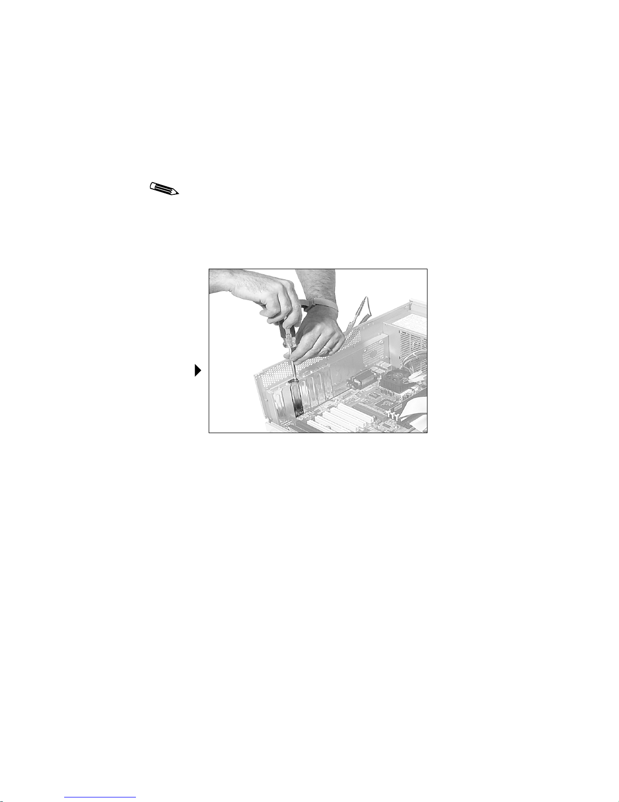
To install the board
1. Remove the blank bracket from the back of any
available PCI slot.
12
Removing a
blank bracket
Page 25
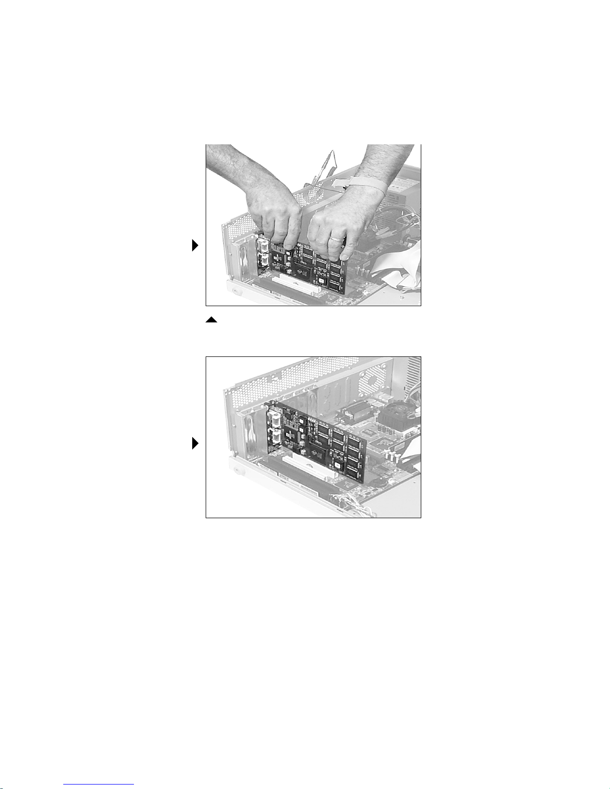
Installing an
Md5/DFP board
Installing the Md5/DFP Board | 13
2. Insert the Md5/DFP board firmly into the slot.
Installed
Md5/DFP board
Installing an Md5/DFP board
3. Make sure the board connector pins are aligned with the slot.
4. Secure the mounting bracket with the bracket screw.
5. Replace the cover.
Page 26

| Installing the Board and Driver in a PC
To install multiple boards
Remember these tips when installing multiple boards:
• The Windows 2000 driver supports as many Md5/DFP
boards as your system’s power supply and available PCI
slots can support.
• For proper installation on both Windows 2000 and
Windows NT systems, you must install all the boards
first and then the drivers.
• The Windows NT driver (version 4.4.0 or later) supports
up to 8 Md5/DFP boards (16 screens).
• You cannot mix DOME board types; additional boards
must be Md5/DFP boards (Windows NT only).
• Each board requires less than 3 amps of +5V.
• You must disable VGA mode on all but one Md5/DFP
board if multiple boards are in use. See “Enabling or
disabling VGA mode” on page 9.
14
Page 27

Connecting a Digital Display
After you install the Md5/DFP board in your computer,
connect your flat panel to the board. For more information,
refer to the installation guide for the digital display.
If you are connecting the Md5/DFP board to a DOME digital
flat-panel display, refer to the C3 or C5 Digital Display
Installation and Maintenance Guide.
Connecting a Digital Display | 15
Page 28
16 | Installing the Board and Driver in a PC
Installing the Windows 2000 Driver
This procedure assumes the Windows 2000 operating
system is already installed on your computer. If it is not,
refer to the Microsoft Windows 2000 documentation.
Install all DOME boards before you install the driver.
See “Preparing for Board Installation” on page 8 for
instructions. Then restart your system and install the
driver for each board separately.
To install the driver
1. Turn on the computer, and highlight Microsoft Windows
2000 Professional. Press <F8> during the system boot and
select Enable VGA Mode on the Windows 2000 Advanced
Options menu. Then press <Enter>.
2. Log on with administrator privileges.
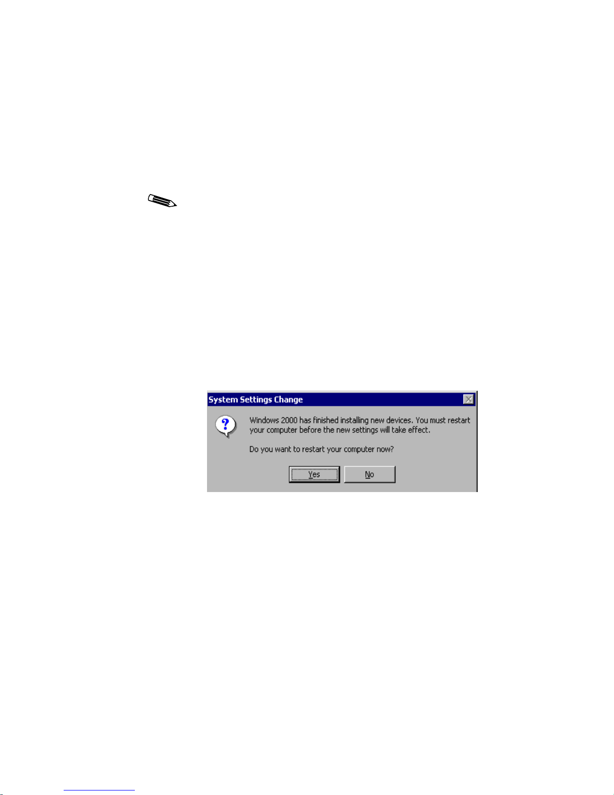
The System Settings Change dialog box appears, indicating
that Windows 2000 recognizes the new hardware device.
3. Click Yes to restart your computer.
Page 29
Installing the Windows 2000 Driver | 17
4. Highlight Microsoft Windows 2000 Professional.
Press <F8> during the system boot and select Enable
VGA Mode on the Windows 2000 Advanced Options
menu. Then press <Enter>.
5. Log on with administrator privileges.
6. Insert the WINFP CD, and browse to find the
Win2k\MD5dfp
directory.
7. Double-click Setup.exe.
The Setup.exe file is an InstallShield Wizard that guides
you through the installation process.
The initial display driver installation dialog box appears.
Page 30
18 | Installing the Board and Driver in a PC
8. Proceed through the installation (license agreement and
readme files).
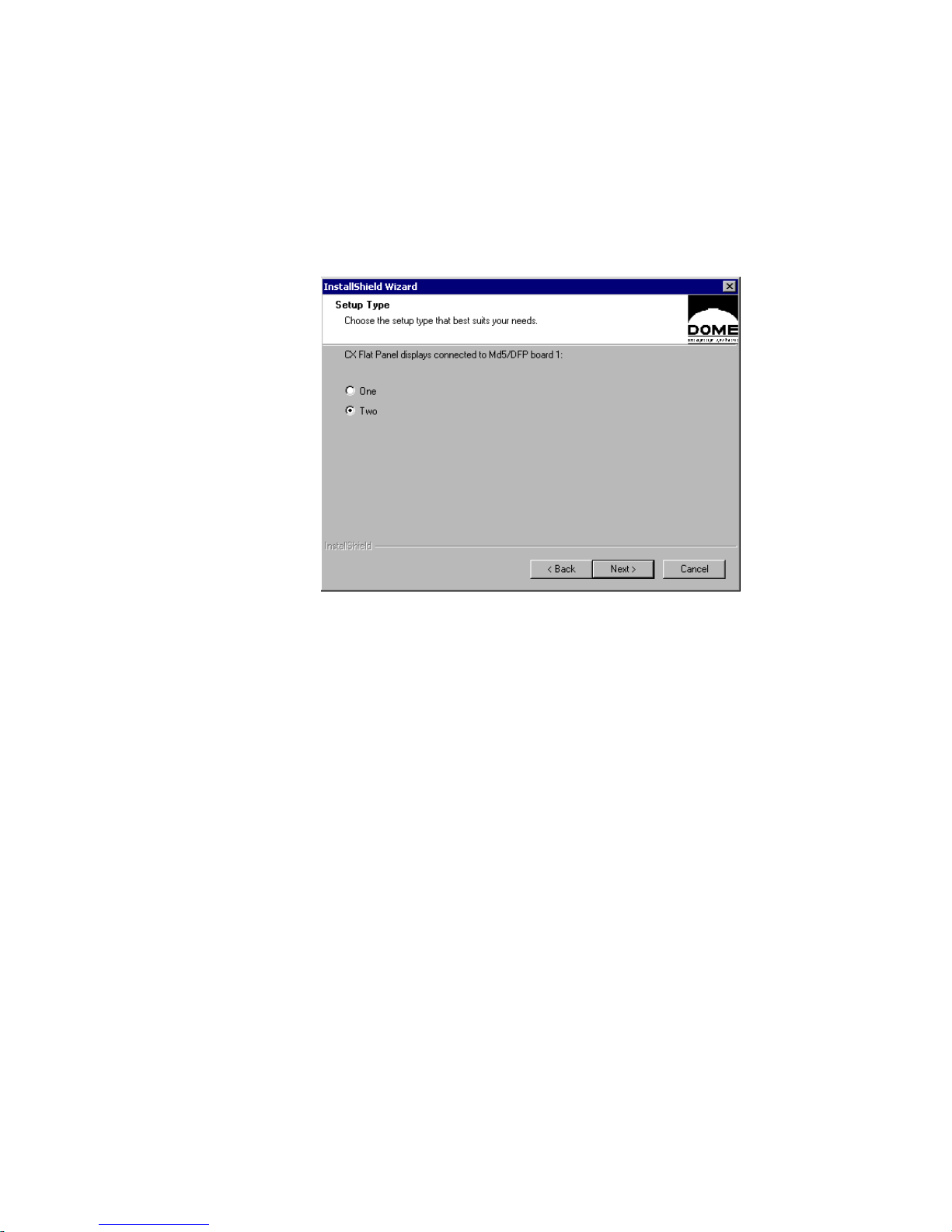
The Setup Type dialog box appears.
9. Select One or Two displays as connected to your Md5/DFP
board, and click Next.
The Setup Type dialog box appears for each Md5/DFP board
you install.
10. Click Yes on the Digital Signature Not Found dialog box to
continue the installation.
This dialog box appears for each CX display you install.
The End of Driver Installation dialog box then appears
upon completion.
11. Select Yes, I want to restart my computer now, and
click Finish.
The Md5/DFP driver loads upon system restart.
Page 31

Installing the Windows 2000 Driver | 19
To modify an existing configuration
1. Insert the WINFP CD, and browse to find the
Win2k\MD5dfp
2. Double-click Setup.exe.
The Welcome dialog box appears.
directory.
3. Select Modify, and click Next.
Page 32

20 | Installing the Board and Driver in a PC
The Setup Type dialog box appears.
4. Choose Update Md5/DFP Driver for Board x to modify
the installed driver, where x is 1 for the first board, 2 for the
second board, and so on. Or select Add a Display for Board x
to add a second display to an existing board installed as a
single head. Click Next.
The Setup Type dialog box appears for each Md5/DFP board
you install.
The Digital Signature Not Found dialog box appears.
5. Click Yes to continue the installation.
The Digital Signature Not Found dialog box appears for
each CX display installed.
The End of Driver Installation dialog box appears
upon completion.
6. Select Yes, I want to restart my computer now, and
click Finish.
7. Click Finish on the Maintenance Complete dialog box.
The Md5/DFP driver loads upon system restart.
Page 33

Installing the Windows 2000 Driver | 21
To install the driver for an additional board
1. Turn off the power to your computer.
If you leave the computer turned on, you might suffer
electric shock or cause damage to both the computer
components and the Md5/DFP board.
2. Install the board, and follow the precautions and installation
steps on pages 8–13.
Make sure VGA is disabled on all Md5/DFP boards you
install subsequently.
3. Check that all flat-panel displays are connected and
powered on.
4. Turn on your computer and boot into VGA mode.
5. Log on with administrator privileges.
The Windows 2000 operating system recognizes the new
hardware device and prompts you to confirm the installation
of the DOME Md5/DFP board.
6. Click Yes.
7. Insert the WINFP CD, browse to find the
Win2k\MD5dfp\fp.5.0.x.yyy directory
(where x.yyy is a number that completes
the driver version, as in fp.5.0.1.009).
8. Continue the installation, then do either of the following:
• Install the second display on the board. (See page 22.)
Enable your display and set the resolution. (See page 24.)
• Restart your computer in normal mode if you have
installed a single-headed board. Enable your display and
set the resolution. (See page 24.)
Page 34

22 | Installing the Board and Driver in a PC
To modify the configuration of a dual-headed board
1. Browse to the Win2k\MD5dfp\fp.5.0.x.yyy directory,
and double-click Setup.exe.
This dialog box appears.
2. Choose Modify, and click Next.
The Setup Type dialog box appears for each Md5/DFP
board in the system.
Page 35

Installing the Windows 2000 Driver | 23
3. Select one of these options, then click Next.
• Update Md5/DFP Driver for Board x to modify the
installed driver, where x is 1 for the first board, 2 for
the second board, and so on. The Setup Type dialog box
appears for each Md5/DFP board you install.
• Add a Display for Board x to add a second display to
an existing board installed as a single head. The Digital
Signature Not Found dialog box appears.
4. Click Yes.
The Digital Signature Not Found dialog box appears for
each CX display installed.
The End of Driver Installation dialog box appears
upon completion.
5. Select Yes, I want to restart my computer now, and
click Finish.
6. Click Finish to close the InstallShield Wizard.
The Md5/DFP driver loads upon system restart in
normal mode.
Page 36

24 | Installing the Board and Driver in a PC
To enable a display and set the display resolution
1. Boot your computer in normal mode.
2. Log on with administrator privileges.
3. Right-click the desktop, and select Properties -> Settings.
4. Click the Display list and select Default Monitor and
DOME Md5/DFP.
5. Select Advanced -> Adapter -> List All Modes.
6. Highlight the desired resolution, and click OK.
7. Select Apply -> OK from the Default Monitor and
DOME Md5/DFP Properties dialog box.
8. Select Extend my Windows desktop onto this monitor, and
click Apply.
This message appears:
Windows will now apply your new desktop settings.
The original desktop will be restored if the
settings are not applied correctly.
9. Click OK to accept the new settings, or Cancel to revert to
the original settings.
If you have installed two or more CX displays, enable them as
described in steps 3–9.
Not all boards support two displays. Boards with part number
55-MD5FP2-xx drive two displays. To determine the part
number of your Md5/DFP board, check the sticker with the
CE mark on the video connector.
Page 37

Configuring Display Settings on Windows 2000 | 25
Configuring Display Settings on Windows 2000
After you install the board and driver and set the default display
(see table below), you can change the resolution or any other
configuration option.
Use this tab... To set the default display for...
DOME tab Displays attached to the
Windows 2000 desktop
Properties ->
Settings tab
Displays not attached to the
Windows 2000 desktop
The Windows 2000 operating system renumbers and reassigns
screens as you add them to the configuration. Set resolutions
or preferences only after all boards and screens are installed.
Restart your system to make sure the screen assignments
are stable.
Determining screen assignments
Click Identify in the Settings tab to match screens to boards.
Using the DOME tab to change display properties
You can change the display properties, such as resolution,
palette options, and brightness, using the DOME tab after
the display is attached to the Windows 2000 desktop.
Page 38

26 | Installing the Board and Driver in a PC
To use the DOME tab
1. Log on with administrator privileges.
2. Right-click the desktop, and select Properties -> Settings.
The Settings tab appears.
3. Select Default Monitor and DOME Md5/DFP Properties
from the Display list.
Make sure the box for Extend my Windows desktop onto
this monitor is checked.
4. Select Advanced -> DOME to select a resolution.
The DOME tab appears.
Page 39

Configuring Display Settings on Windows 2000 | 27
Changing the resolution
The Resolution field of the DOME tab lets you choose the
desired resolution in either portrait or landscape mode.
To change the resolution
1. Select a resolution, and click Apply.
When you use the DOME tab to set the resolution for one
display of a dual-headed DOME board, the second display
assumes the same resolution.
The DOME Display Resolution dialog box appears.
2. Click OK within 15 seconds to accept the new settings, or
ignore the message to revert to the original settings.
The resolution changes on both installed screens, and
a message appears prompting you to accept or cancel
the new resolution.
Page 40

28 | Installing the Board and Driver in a PC
3. Click OK to set this resolution, or Cancel to return to the
DOME tab.
If you select OK, this message appears.
4. Click OK. You can now use the display.
Setting brightness
In the Brightness field of the DOME tab, slide the scroll box left
or right, or use the left and right arrows, to set brightness for each
flat panel. (The default brightness is 100%.) Click OK.
Page 41

Configuring Display Settings on Windows 2000 | 29
Setting palette options
DOME palette options must coordinate with the primary display.
All flat panels must be set to either palette devices or non-palette
devices, as shown in this table.
Palette Device Non-Palette Device
• Dynamic gray • Nonlinear static gray
Grayscale
palettes
• Pseudocolor
a. Color option available for flat-panel displays.
a
• Static gray
All DOME boards that support multiple displays also
support differing palette options on multiple screens
attached to the same board.
This illustration shows the assignment of values on the
grayscale palettes.
Page 42

30 | Installing the Board and Driver in a PC
Palette options with multiple displays
The SelectPalette and RealizePalette functions in the
Microsoft Developer’s Network, or MSDN, work across all
flat-panel displays if the primary panel is palettized. The
palettes of all palettized devices are synchronized. If, however,
the primary panel is not palettized, the SelectPalette and
RealizePalette
functions select the palette into the back-
ground, and palettized devices are not synchronized.
Desktop icons
The palette specifications of the primary display determine
how desktop icons are drawn. For example, the desktop icons
appear gray on a color screen if the primary display is set to
a gray palette.
This table defines the palette options that work on primary
and secondary displays (see the first and second columns).
The third column indicates whether the palette combination
of the primary and secondary displays works.
Primary Display Secondary Display Combination OK?
Commodity board at
16 bits per pixel (bpp)
Commodity board at
16 bpp
Commodity board at
16 bpp
Dynamic gray Commodity board at
Dynamic gray Dynamic gray Yes
Dynamic gray Static gray No
Dynamic gray No
Static gray Yes
Nonlinear gray Yes
Yes
16 bpp
(Cont.)
Page 43

Configuring Display Settings on Windows 2000 | 31
Primary Display Secondary Display Combination OK?
Dynamic gray Nonlinear static gray Yes
Dynamic gray Pseudocolor Yes
Static gray Commodity board at
Yes
16 bpp
Static gray Dynamic gray No
Static gray Static gray Yes
Static gray Nonlinear static gray Yes
Static gray Pseudocolor No
Nonlinear static gray Commodity board at
Yes
16 bpp
Nonlinear static gray Dynamic gray No
Nonlinear static gray Static gray Yes
Nonlinear static gray Nonlinear static gray Yes
Nonlinear static gray Pseudocolor No
Pseudocolor Commodity board at
Yes
16 bpp
Pseudocolor Dynamic gray Yes
Pseudocolor Static gray No
Pseudocolor Nonlinear static gray Yes
Pseudocolor Pseudocolor Yes
Page 44

32 | Installing the Board and Driver in a PC
Setting driver options
Beware that the Disable DirectDraw driver option has specific
conditions which may affect your display.
To disable DirectDraw
In the Driver Options field of the DOME tab, select
Disable DirectDraw. Then click Apply or OK.
Getting information
Information about the flat panel, board, and driver appears on
the lower half of the DOME tab.
Flat panel information includes panel type, serial number, and
on-board temperature (in degrees Celsius). The temperature
reading of a flat panel is given when you first open the panel
and if you later select it. The revision numbers of the microcontrollers are also included.
General information includes driver version, library version, and
board type.
Page 45

Uninstalling a DOME Device on Windows 2000 | 33
Uninstalling a DOME Device on Windows 2000
You can uninstall DOME devices by using the Uninstall DOME
Device feature on the DOME tab and the Microsoft control panel.
• Uninstall single-headed DOME devices using the Microsoft
control panel.
• Uninstall dual-headed DOME devices by clicking Uninstall
DOME Device on the DOME tab and removing the device
through the Microsoft control panel.
The DOME control panel determines if you are uninstalling the
devices in the correct order.
Remember these tips when uninstalling DOME devices:
• You can uninstall both single- and dual-headed DOME
display boards.
• You must uninstall a dual-headed DOME device on a
display-by-display basis. Remove the sister device first
and the primary device second.
• The device that you are uninstalling must be attached to
the Windows 2000 desktop.
• You cannot uninstall the primary display.
Page 46

34 | Installing the Board and Driver in a PC
To uninstall a single-headed device
1. Select Start -> Settings -> Control Panel ->
Administrative Tools.
2. Click Computer Management.
The Systems Tools dialog box appears.
3. Click Device Manager.
4. Click Display Adapters.
A list of currently installed display devices appears.
5. Highlight the adapter you want to remove. Right-click and
choose Uninstall.
6. Click OK in the Confirm Device Removal dialog box.
The Systems Settings Change dialog box appears. To finish
removing the hardware, you must restart the computer.
Page 47

Uninstalling a DOME Device on Windows 2000 | 35
7. Click Yes to restart the computer.
The device is now removed from Windows 2000.
8. Turn off the computer after it restarts and remove the
Md5/DFP board.
For more information on removing devices through the
Microsoft control panel, see your Microsoft documentation.
To uninstall a dual-headed device
1. Right-click on the desktop, and select Properties ->
Advanced for the sister device.
2. Select DOME -> Uninstall DOME Device.
3. Restart the computer.
Once you restart the computer, the sister device no longer
appears in Windows Display Properties.
4. Select Start -> Settings -> Control Panel ->
Administrative Tools.
5. Click Computer Management.
The Systems Tools dialog box appears.
6. Click Device Manager.
Page 48

36 | Installing the Board and Driver in a PC
7. Click Display Adapters.
A list of currently installed display devices appears.
8. Highlight the adapter shown with the Display Warning icon.
Right-click and choose Uninstall.
9. Click OK on the Confirm Device Removal dialog box.
The device is now removed from Windows 2000.
10. Restart the computer.
To finish uninstalling the primary device of the dual-headed
DOME display board, see “To uninstall a single-headed
device” on page 34.
Page 49

Troubleshooting for Windows 2000 | 37
Troubleshooting for Windows 2000
If you have display problems with the Md5/DFP board and
driver, try these troubleshooting tips. If you need further
assistance, contact DOME Support at (781) 895-1155 or via
support@dome.com.
Sister device
Use the DOME tab to begin uninstalling the sister device. If you
click Uninstall DOME Device to uninstall the primary display,
this dialog box appears.
Single-headed display board
Use Administrative Tools in the Windows control panel to
uninstall a single-headed DOME display board. If you try to
uninstall a single-headed board by clicking Uninstall DOME
Device on the DOME tab, this dialog box appears.
This message also appears if you try to uninstall the primary
display of a dual-headed device through the DOME tab after
you have uninstalled its sister device.
Page 50

38 | Installing the Board and Driver in a PC
Unsigned driver load error
If an unsigned driver cannot be loaded message appears
on the screen, set the HKCU\Software\Policies\ Microsoft\
Windows NT\Driver Signing
DOME drivers.
To install the driver
1. Select Start -> Settings -> Control Panel -> System.
The System Properties dialog box appears.
2. Select Hardware -> Driver Signing… in the
Device Manager section.
3. Select either Ignore or Warn to allow installation of the
DOME driver and other unsigned drivers.
• If you select Ignore, the installation program ignores the
lack of a valid Catalog file with a digital signature.
• If you select Warn, the installation displays the message
Digital Signature Not Found
continue or cancel.
key to allow installation of
and prompts you to
Impaired screen resolution
If one screen of a dual-headed board looks strange after you
change the resolution of another screen, make sure the sister
displays have the same resolution settings by taking one of
these actions:
• Boot into VGA mode and change settings on one screen to
match the other.
• Use the DOME tab to change the resolution. It automatically
changes the sister display resolution to match.
Page 51

Troubleshooting for Windows 2000 | 39
System crash and reboot cycle
If you are using the DOME board to support VGA display, your
system may crash and lock into a reboot cycle during the initial
installation of the Windows 2000 driver.
Press <F8> during the system boot to break the cycle. Then
select Enable VGA Mode on the Windows 2000 Advanced
Options menu, and press <Enter>.
Overwriting installation file
The Confirm File Replace dialog box appears if the installation
CD contains a file older than the one currently on your system.
Click No to the question Overwrite the newer file?
or click No to All.
Page 52

40 | Installing the Board and Driver in a PC
Additional Components for Windows 2000
These additional DOME software components run on
Windows 2000 systems using the Md5/DFP board.
Dynamic link library
The mdpcint.dll dynamic link library, or DLL, is a group
of functions that can link to DOME applications, such as the
DOME Image-Processing Library and Calibration TQA.™
The DLL installs automatically when you load the
Windows 2000 driver.
DIMPL library
The DOME Image-Processing Library, or the DIMPL library,
provides a collection of functions for image manipulation.
The DIMPL library uses the DirectDraw™ facilities in the
Windows 2000 operating system and works cooperatively
with the DOME driver.
DimplX control
The DimplX control is the ActiveX interface to the DIMPL
library. It provides an easy-to-use interface to the powerful
DIMPL functions. It also uses the DirectDraw facilities in
the Windows 2000 operating system.
Page 53

Calibration TQA
DOME Calibration TQA 2.0.3 or later works on a Windows 2000
system that meets the requirements of either full or partial
Windows NT 4.0-compatible mode.
The Windows 2000 system must meet these requirements:
• All DOME screens must use the same palette options.
• All DOME screens must be in nonnegative space on the
Windows desktop.
Refer to the PCI or PCX Products Developer’s Guide for more
information about the Windows NT 4.0-compatible modes.
You can run Calibration TQA 2.0.3 or later on a system that
includes both DOME boards and other brands of boards.
Do not change any Windows display settings while the
Calibration TQA application is running. Calibration TQA
and other mdpcint.dll-reliant applications may behave
unpredictably if changes are made while the application
is active.
Additional Components for Windows 2000 | 41
Page 54

42 | Installing the Board and Driver in a PC
Installing the Windows NT 4.0 Driver
This procedure assumes the Windows NT 4.0 operating system
is already installed on your system. If it is not, refer to the
Microsoft Windows NT 4.0 documentation.
Install the Md5/DFP board and connect it to the flat panel before
you install this driver. Failure to do so may cause problems with
the installation.
To install the driver
1. Turn on the power to your computer, and select
Windows NT Workstation Version 4.00 [VGA].
2. Log on with administrator privileges.
You need administrator privileges to change the
display settings.
3. Right-click the desktop, and select Properties -> Settings.
The Settings tab appears.
4. Click Display Type….
The Display Type dialog box appears.
5. Click Change… in the Adapter Type section of the
dialog box.
The Change Display dialog box appears.
6. Click Have Disk….
The Install From Disk dialog box appears, containing
this field:
Copy manufacturer’s files from:
A:\
Page 55

Installing the Windows NT 4.0 Driver | 43
7. Insert the WINFP CD and browse to the
winnt4\fp.4.4.x.yyy directory (where
x.yyy is a number that completes the driver
version, as in fp.4.4.2.012).
8. Click OK to select the oemsetup.inf file.
The Change Display dialog box appears with this choice:
DOME imaging systems Md5/DFP
9. Select DOME imaging systems Md5/DFP, then click OK.
The Third-Party Drivers dialog box appears, prompting you:
Do you wish to proceed?
10. Click Yes.
A progress bar appears, and the Installing Driver dialog box
appears with this message:
The drivers were successfully installed.
11. Click OK.
12. Click Close on the Display Type dialog box and on the
Display Properties dialog box.
The System Settings Change dialog box appears,
prompting you:
Do you want to restart your computer now?
13. Click Yes.
14. When the system restarts, select Windows NT Workstation
Version 4.00 [VGA].
15. Configure your display settings. (See page 44.)
Page 56

44 | Installing the Board and Driver in a PC
Configuring Display Settings on Windows NT
After you install the board and driver, set the board to support
the flat panel through the Settings tab of the Display Properties
dialog box. You can then use the DOME tab to change display
properties.
To set the display resolution
1. Log on with administrator privileges.
The Invalid Display Setting dialog box appears.
2. Click OK.
The Settings tab in the Display Properties dialog
box appears.
Page 57

Sample Detected
Adapter dialog box
Configuring Display Settings on Windows NT | 45
3. Click List All Modes….
The Detected Adapter dialog box appears.
The dialog box on your screen displays the values that
exist in your binary .cfg file, which may be different
from the values displayed in this illustration.
4. Select the resolution that matches the flat panel you are
using for display.
5. Click OK.
Your flat panel(s) must be connected to test these
resolutions.
6. Click Test.
The Testing Mode dialog box appears, explaining that
the new mode is being tested.
Page 58

46 | Installing the Board and Driver in a PC
7. Click OK.
A test bitmap appears.
The Testing Mode dialog box appears, prompting you:
Did you see the test bitmap properly?
8. Click Yes if the test bitmap displayed correctly, or No if
it didn’t.
If No, the Testing Mode dialog box appears, prompting you
to try different settings for your display. Click OK. Repeat
steps 3–8 to perform the test with a different resolution.
9. Select Large Fonts in the Font Size field (optional).
Selecting Large Fonts on the Settings tab does not
make a significant difference in font size at very high
resolutions. The DOME driver installs extra-large fonts
in your C:\dome\tools directory. To add those fonts
to your display properties, follow the instructions for
“DOME large fonts” on page 55.
10. Click OK.
The display resolution is now set properly for the
Md5/DFP board.
This message appears:
Do you want to restart your computer now?
Page 59

Configuring Display Settings on Windows NT | 47
11. Click No.
You can now change your display properties using the
DOME tab.
12. Right-click the desktop, and select Properties -> DOME.
A dialog box prompts you to choose a configuration file
(because the system is currently in VGA mode).
13. Click Open to use the default configuration file (fp5pcy.cfg)
on your system.
The DOME tab for VGA mode appears.
Not all flat-panel display properties and information
appear in VGA mode. After you restart your computer,
enter the DOME tab to access all flat-panel configuration
options and information.
14. Click OK or Apply to activate all the new settings.
This message appears:
Do you want to restart your computer now?
15. Click Yes.
The system prompts you to select an operating system.
16. Select Windows NT Workstation 4.00.
Page 60

48 | Installing the Board and Driver in a PC
Using the DOME tab to change display properties
Use the DOME tab to change display properties and to get
information about the flat panel. See pages 49–54 for more
information on specific configuration options and features.
To use the DOME tab
1. Right-click the desktop, and select Properties -> DOME.
The DOME tab appears.
2. Select your desired settings.
3. Click Apply or OK after you set the options.
You can make several changes to your configuration at
one time. After you have selected all the new settings,
restart your computer to activate them.
Page 61

Configuring Display Settings on Windows NT | 49
Using the DOME tab online help
The Windows NT driver (version 4.4.0 or later) provides online,
context-sensitive help for the DOME tab. You can access the help
in either of these two ways:
• Click the question mark (?) button on the title bar, then click
on the DOME tab field with which you need assistance.
• Move the cursor to the DOME tab field with which
you need assistance, and press <F1>.
Setting the screen configuration
In the Configuration field of the DOME tab, highlight the screen
number and orientation. Click Apply or OK.
Each Md5/DFP board supports one or two digital flat panels.
Keep these points in mind:
• Version 4.4.0 or later of the driver supports up to 8 boards
(16 screens).
• The screens are assigned to the boards in the order in which
the boards are found on the bus. For example, if the first board
is a dual-headed board, it controls panels 1 (one) and 2.
Changing the resolution
In the Resolution field of the DOME tab, highlight the desired
resolution then click Apply or OK.
Setting brightness
In the Brightness field of the DOME tab, select the flat panel from
the drop-down box. Flat Panel 1 (one) is the left or top flat panel.
Slide the scroll box or use the left and right arrows to set
brightness for each flat panel. (The default brightness is 100%.)
Click OK.
Page 62

50 | Installing the Board and Driver in a PC
Setting palette options
In the Palette Options field of the DOME tab, use the pull-down
menu to select a palette. Then click Apply or OK.
Under Windows NT 4.0, the Md5/DFP board supports the
palettes in this table.
Palette Bits per Pixel
Color 8
Dynamic gray 8
Nonlinear static gray 8
Static gray 8
This illustration shows the assignment of values on the
grayscale palettes.
Grayscale
palettes
Page 63

Configuring Display Settings on Windows NT | 51
Color palette
The color palette displays 8 bits of color (3 bits of red, 3 bits of
green, and 2 bits of blue).
You can change the pixel depth for color display through
the Settings tab in the Display Properties dialog box. Click
Palette Options and select Color Palette.
Dynamic gray palette
The dynamic gray palette reserves the first and last 10 entries in
the palette for the Windows NT operating system, but you can
manipulate the middle 236 entries. Your application can create a
256-entry gray ramp in any 8-bit driver by calling the Windows
API function SetSystemPaletteUse(), but doing so causes all
icons to be redrawn in black and white.
The dynamic gray palette accommodates gray-mapped Windows
colors for the first and last 10 palette entries.
Nonlinear static gray palette
The nonlinear static gray palette sets the first and last 10 palette
entries to gray-mapped Windows colors. The middle 236 entries
are ramped in ascending order, excluding the first and last
10 palette entries. Windows applications that use the first and
last 10 palette entries as Windows colors display correctly on
the screen.
Page 64

52 | Installing the Board and Driver in a PC
Although the nonlinear static gray palette provides correct
colors for applications using the Windows palette, colors
display incorrectly if the application assumes that a static
palette is always ramped.
To run DOME calibration software with the nonlinear static
gray palette, use Calibration TQA 2.0.3 or later.
Applications cannot set the nonlinear static gray palette.
They must read the palette from the operating system and
use it when drawing directly to the framebuffer. Application
colors display incorrectly if the application assumes all 8-bit
framebuffers have palettes that can be set.
Static gray palette
The static gray palette provides 256 shades of gray in a static
palette. This palette does not reserve the first and last 10 palette
entries for icons and other standard Windows graphics, which
frees the entire grayscale ramp for applications.
The static gray palette does not provide gray-mapped Windows
colors for the first and last 10 palette entries. Because the framebuffer assumes the Windows palette is in use, applications that
draw directly to the framebuffer display incorrectly. For example, icons and button bitmaps may display in black and white.
To run DOME calibration software with the static gray palette,
use Calibration TQA 2.0.3 or later.
Applications cannot set the static gray palette. They must
read the palette from the operating system and use it when
drawing directly to the framebuffer. Application colors display
incorrectly if the application assumes all 8-bit framebuffers have
palettes that can be set.
Page 65

Setting driver options
The Disable DirectDraw driver option has specific conditions
that may affect your display. Be sure to read the next sections
before you choose this option.
To disable DirectDraw
In the Driver Options field of the DOME tab, select
Disable DirectDraw. Then click Apply or OK.
DirectDraw and multiheaded support
DirectDraw is an API that allows direct manipulation of the
video display. DirectDraw applications expect the screen to
be represented as a single element. If you are using multiple
Md5/DFP screens, then more than one screen represents the
Windows NT desktop.
With multiple displays representing the Windows NT desktop,
DirectDraw applications cannot access the entire desktop and
may not work properly.
Configuring Display Settings on Windows NT | 53
DirectDraw limited screen size
Under the Windows NT 4.0 operating system, Build 1381,
DirectDraw supports screen sizes only up to 2048 x 2048 pixels.
DirectDraw applications may not function properly with bigger
screen sizes.
Microsoft is aware of this problem and plans to correct it in a
future release of W indows NT. Although DOME has made efforts
to provide whatever support possible within this limitation,
DOME cannot ensure DirectDraw compatibility with either
multiple screens or a screen size greater than 2048 x 2048 pixels.
Page 66

54 | Installing the Board and Driver in a PC
Getting information
In the Flat Panel Information field, select Panel 1 (one) or Panel 2.
Flat Panel 1 (one) is the left or top flat panel.
This information includes panel type, serial number, and
on-board temperature (in degrees Celsius). The temperature
reading of a flat panel is given when you first open the panel
and if you later select it. Revision numbers of the microcontrollers are also included.
DOME product information includes driver version, library
version, number of boards, and maximum number of screens.
Page 67

Additional Configuration Options on Windows NT | 55
Additional Configuration Options on Windows NT
You can configure the DOME Windows NT driver to modify
screen appearance, relocate dialog boxes across screens, and
activate a screen saver.
DOME large fonts
The DOME driver supplements the standard Windows fonts
with DOME large fonts to compensate for high-resolution
display. When the DOME Windows NT driver is installed,
it places the large fonts in the C:\dome\tools directory.
If you want to use the DOME large fonts, you must install
them to your display properties.
To install DOME large fonts
1. Double-click My Computer -> C: -> DOME -> Tools.
A list of files appears.
2. Double-click the desired font from the list of files:
• DOMEl.reg (DOME large)
• DOMExl.reg (DOME extra large)
• DOMExxl.reg (DOME extra extra large)
3. Close all applications and windows.
4. Restart your computer.
DOME large fonts are now available for use in
Display Properties.
5. Right-click the desktop, and select Properties ->
Appearance.
The Appearance tab appears.
6. Click the Scheme pull-down arrow, and select
the desired font.
7. Click OK.
Page 68

56 | Installing the Board and Driver in a PC
To uninstall DOME large fonts
1. Double-click My Computer -> C: -> DOME -> Tools.
A list of files appears.
2. Double-click WinStand.reg.
3. Click OK.
4. Close all applications and windows.
5. Restart your computer.
6. Right-click the desktop, and select Properties ->
Appearance.
The Appearance tab appears.
7. Click the Scheme pull-down arrow, and select
Windows Standard.
8. Click OK.
To increase cursor size
1. Select Start -> Settings -> Control Panel -> Mouse ->
Pointers.
The Pointers tab appears.
2. Click the Scheme pull-down arrow, and select
Windows Standard (extra large).
3. Click OK.
4. Close the Control Panel dialog box.
Installing DOME large fonts does not automatically increase the
cursor size. To return to the standard cursor size, follow steps
1–2 of this procedure, and select Windows Standard from the
Scheme pull-down menu.
Page 69

Additional Configuration Options on Windows NT | 57
Customizing item and font size
You can customize the sizes of icons, menus, and title bars and
the appearance of fonts. To do so, choose the Appearance tab
from the Display Properties dialog box and adjust the Item Size
and Font Size fields.
This table provides recommended item and font sizes for
high-resolution displays.
This
selection…
Active
Title Bar
Icon Icons on
Menu All menus,
Sets font and size
of this item…
Active window
title bar
the desktop
b
both system- and
Its default
settings are…
Item size: 18
Font size: 8
Item size: 32
Font size: 8
Item size: 18
Font size: 8
Its recommended
settings are…
a
Item size:
--
Font size: 10 or 12
Item size: 48
Font size: 10
Item size:
a
--
Font size: 10 or 12
application-level
Message
Box
Tool Tip All tool tip text, both
All message
box text
system- and
Item size: n/a
Font size: 8
Item size: 18
Font size: 8
Item size: n/a
Font size: 10 or 12
Item size:
a
--
Font size: 10 or 12
application-level
a. The item size adjusts automatically if the font size changes.
b. If the Item or Font size is too large, the icon and text may be cropped.
If this occurs, adjust Icon spacing by right-clicking on the desktop and
choosing Line Up Icons or Arrange Icons. You can also change icon
spacing by choosing Icon Spacing (Horizontal) and Icon Spacing
(Vertical), and adjusting the Size setting to a larger number. (The
default spacing is 43.)
Page 70

58 | Installing the Board and Driver in a PC
DOME DlgFix software
The DOME DlgFix software automatically relocates all dialog
boxes to the upper-left screen, preventing dialog boxes from
splitting across screens.
Dialog box
splits across
screens when
DlgFix is not
running
Dialog box
appears in
upper-left
screen when
DlgFix is
running
The DOME DlgFix software installs automatically when
you load the Windows NT 4.0 driver.
Page 71

Additional Configuration Options on Windows NT | 59
Limitations of DlgFix
Because of limitations in the Windows NT operating system,
DlgFix
the startup programs; logon dialog boxes are still split
between screens.
cannot modify dialog box locations until you run
To run DlgFix
Type C:\dome\tools\DlgFix at the DOS prompt.
The DOME DlgFix icon appears on your taskbar to indicate
that DlgFix is running.
To add DlgFix to the startup menu
Type C:\dome\tools\DlgSetup at the DOS prompt.
After you type this command, DlgFix automatically
starts each time you boot your computer.
To uninstall DlgFix
Type C:\dome\tools\DlgUnins at the DOS prompt.
Your system may experience a slight degradation in
performance while running DlgFix. If you find system
performance unacceptable, uninstall the software as
directed above.
Page 72

60 | Installing the Board and Driver in a PC
DOME DPMS Screen Saver
Display Power Management Signaling (DPMS) provides
a standard way to manage the power used by your display.
DPMS shuts off the backlight in the flat panel when the
display is not in use. This reduces the power consumption
of the backlight and extends the life of the display.
The DOME DPMS Screen Saver for Windows NT offers a
powerful and flexible way to increase the life of your display
and decrease its power consumption.
How the screen saver works
Like other Windows screen savers, the DOME DPMS Screen
Saver is invoked after the system has received no user input for
a specified number of minutes. Unlike other screen savers, however, the DOME DPMS Screen Saver does not display anything
on the flat panel itself. Rather, it launches another screen saver
that you select to protect the display. Then, after a predetermined
number of minutes, it uses DPMS to shut off the video power to
the display.
There are two delay periods before DPMS is invoked:
• First, the standard screen-saver delay from the last user input
until the screen saver launches.
• Second, from the time the screen saver launches to the moment
DPMS shuts off the video power to the flat panel. After this
delay, DPMS places the flat panel in power-off mode.
The DOME DPMS Screen Saver allows you to select the other
screen saver to use before it invokes power-off mode. It also
allows you to specify up to four periods during the day with
different settings if or when power-off mode is invoked during
each period.
Page 73

Additional Configuration Options on Windows NT | 61
To select the DOME DPMS Screen Saver
1. Right-click the desktop, and select Properties ->
Screen Saver.
The Screen Saver tab appears.
2. Select DOME DPMS Screen Saver from the list of
screen savers.
3. Set the Wait: field with the time (in minutes) that must
elapse before the first screen saver appears.
Page 74

62 | Installing the Board and Driver in a PC
To set up the DOME DPMS Screen Saver
1. Click Settings… on the Screen Saver tab.
This dialog box appears.
2. Select a screen saver from the list.
The screen saver you select appears on your flat panel
before DPMS power-off mode is invoked. You can select
any of the other installed Windows screen savers to
protect the flat panel during that time. The Settings and
Preview buttons enable you to adjust the screen-saver
settings and see a sample of each screen saver.
You can create as many as four distinct periods throughout
the day, with different DPMS settings for each period.
Continue this procedure to set each time period.
Page 75

Additional Configuration Options on Windows NT | 63
3. Set the start time in the Starting at: field.
Use a 24-hour time format, such as 16:30 to indicate 4:30 P.M.
This determines if or when power-off mode is invoked for up
to four different periods of the day.
Leave the start time for a period blank if you don’t want
to use it.
4. Input the number of minutes of additional inactivity
(after the first screen saver displays) that must elapse
before the flat panel enters power-off mode in the
Invoke DPMS after: field.
5. If desired, select Wake at start of period to force the flat
panel to wake up if it is in power-off mode at the start of
the period.
6. If desired, select Never sleep during this period to prevent
a switch to power-off mode during the period.
7. Click OK to keep your settings, or Cancel to discard them.
The Display Properties dialog box appears.
8. Click OK.
Page 76

64 | Installing the Board and Driver in a PC
Remember these tips when you set the screen saver:
• The two delay periods are cumulative. If it takes 15 minutes
of user inactivity for the DOME DPMS Screen Saver to start,
and there is a 30-minute delay until power-off mode is
invoked for the current time period, power-off mode starts
only after a total of 45 minutes of user inactivity.
• After being in power-off mode for a long time, the flat-panel
display can take as many as 30 minutes to reach optimal
performance conditions when the video power is turned on
again. To ensure that the flat-panel display is performing
optimally when you need it, use the DOME DPMS Screen
Saver to force the flat panel to wake up before expected
periods of heavy use.
Page 77

Additional Components for Windows NT | 65
Additional Components for Windows NT
These additional DOME software components run on
Windows NT systems using the Md5/DFP board.
Dynamic link library
The mdpcint.dll dynamic link library (DLL) is a group
of functions that can link to DOME applications, such as the
DOME Image-Processing Library and Calibration TQA.
The DLL installs automatically when you load the
Windows NT driver.
DIMPL library
The DOME Image-Processing Library, or the DIMPL library,
provides a group of functions for image manipulation. The
library uses the DirectDraw facilities in the Windows NT
4.0 operating systems and works cooperatively with the
DOME driver.
DimplX control
The DimplX control is the ActiveX interface to the DIMPL
library. It provides an easy-to-use interface to the powerful
DIMPL functions. It also uses the DirectDraw facilities in
the Windows NT 4.0 operating system.
Page 78

66 | Installing the Board and Driver in a PC
Calibration TQA
To run the DOME calibration software on a Windows NT system,
use Calibration TQA 2.0.3 or later.
You can run Calibration TQA 2.0.3 or later on a system that
includes both DOME boards and other brands of boards.
Do not change any Windows display settings while the
Calibration TQA application is running. Calibration TQA
and other mdpcint.dll-reliant applications may behave
unpredictably if you make changes while the application
is active.
Page 79

Installing the Board and Driver in a
Sun PCI Workstation
In This Chapter
• Preparing for Board Installation 68
• Installing the Md5/DFP Board 71
• Connecting a Digital Display 74
• Installing the Solaris Driver 75
• Configuring Display Settings 77
• Configuring the Windowing Environment 87
• Using the DPMS Screen Saver 89
• Changing the Console 92
Page 80

68 | Installing the Board and Driver in a Sun PCI Workstation
Preparing for Board Installation
Be sure to review the installation requirements for the Sun PCI
workstation before you proceed with board installation. See
pages 4–5.
Before you install the board, read this section carefully. The
information here helps you unpack and install the Md5/DFP
board properly, and use the DIP switches correctly to disable
VGA mode.
Install the board first, then connect the display before you install
the driver. If you install the board and driver incorrectly, you
may not be able to restart your computer.
Unpacking the board
Remove the Md5/DFP board slowly from its package and
static-shielding bag to protect it against electrostatic discharge.
Static electricity can damage the board. When touching the
board or parts of the motherboard, be sure to take these
precautions:
• Wear an antistatic wrist strap.
• Always keep one hand touching a bare metal surface to
provide grounding.
• If you can’t perform a step with just one hand, use both and
return one hand occasionally to the metal surface.
Page 81

To prepare for installation
1. Turn off the power to your computer.
Leave the computer plugged into a grounded power
outlet. This allows the power cord to serve as a ground
for the computer.
If you leave the computer turned on, you might suffer
electric shock or cause damage to both the computer
components and the Md5/DFP board.
2. Remove the cover from the computer according to the
manufacturer’s instructions.
3. Set DIP switch S1 to disable VGA mode.
Disabling VGA mode
The Md5/DFP board cannot operate as a VGA board in a
Sun PCI workstation. You must disable VGA on the board.
This illustration details the location of DIP switches S1 and S2
on the board. Note the on/off position for the switches.
Preparing for Board Installation | 69
DIP switches on
the Md5/DFP
board
Page 82

70 | Installing the Board and Driver in a Sun PCI Workstation
DIP switch S1 setting
Use DIP switch S1 to disable VGA mode. Slide switches 1–4 into
the positions shown in this table.
DIP Switch S1 Position
1ON
2ON
3 OFF
4 OFF
DIP switch S2 setting
The factory setting of switches 1–4 on DIP switch S2 is all OFF.
The default display resolution is 1536 x 2048 with all switches in
the OFF position. If you change the setting for one or more of
the switches, DIP switch S2 overrides the default display mode
programmed on the board. See “Using the default display mode”
on page 77 for more information.
This table shows the factory and optional settings for the
display resolutions that can be set with DIP switch S2.
DIP Switch S2 Positions
Resolution
1536x2048
1536x2048 ON OFF OFF OFF
2048x1536 OFF ON OFF OFF
2048x2560 ON ON OFF OFF
a. Factory setting.
a
1234
OFF OFF OFF OFF
Page 83

Installing the Md5/DFP Board
Follow the safety precautions described on page 68 before you
install the board.
To install the board
1. Locate the slot you want to use for the board, then remove
the backplate from the slot.
Removing a
backplate
Installing the Md5/DFP Board | 71
The slots are usually labeled on the motherboard, but
you may need to consult your Sun documentation for
a slot ID chart.
Page 84

72 | Installing the Board and Driver in a Sun PCI Workstation
2. Position the board’s backplate into the opening at the back
of the computer.
Installing an
Md5/DFP board
3. Make sure the board’s connectors are aligned with the
connectors on the motherboard, then press down until
the board is firmly seated.
Installed
Md5/DFP board
4. Secure the board with the screw for the backplate.
5. Replace the cover.
6. Turn on the workstation, and boot with the -r option.
Page 85

Installing the Md5/DFP Board | 73
To install multiple boards
Repeat the procedure in “Installing the Md5/DFP Board” on
page 71 for each board.
Remember these tips when installing multiple boards:
• You can install as many Md5/DFP boards as your system’s
power supply and available PCI slots can support.
• Each board requires less than 5 amps of +5V. In addition,
you can install different boards in the same system.
Page 86

74 | Installing the Board and Driver in a Sun PCI Workstation
Connecting a Digital Display
After you install the Md5/DFP board in your system, connect
your flat panel to the board. For more information, refer to
the installation guide for the digital display.
If you are connecting the Md5/DFP board to the DOME C3 or
C5 flat panel, refer to the C3 or C5 Digital Display Installation and
Maintenance Guide.
Page 87

Installing the Solaris Driver
This procedure assumes that the Solaris 2.5.1 or later operating
system is already installed on your system. If it is not, refer to the
Sun documentation.
Installing the Md5/DFP driver for your Sun host requires about
500 KB of free space:
• 200 KB in /kernel/drv
• 100 KB in /usr/openwin/server/modules
• 200 KB in /usr/lib
The installation procedure for Solaris performs these tasks:
• Adds the device driver
• Adds the OpenWindows™ loadable DDX driver
• Modifies the OWconfig file
• Installs the DOMEmdlib shared object library
To install the driver
1. Log on as root.
Installing the Solaris Driver | 75
If a previous version of the driver software exists on
your system, you must remove it before you install
the new package. To do so, type pkgrm, and select the
DOMEmd5f and DOMEmdlib packages for removal.
If the DOMEmdlib package already installed on the
system is newer than that on the CD, do not remove it.
2. Insert the DOME Md5/DFP Solaris driver CD into the
CD-ROM drive.
3. Mount the CD device if the system does not automount it.
Then type:
cd /cdrom/dome
Page 88

76 | Installing the Board and Driver in a Sun PCI Workstation
4. To transfer the software packages to the system, type:
pkgadd -d md5fZZZ.pkg
where ZZZ = the revision of the software on the CD.
Check the name of the file on the CD to get the
software revision.
This message appears:
The following packages are available:
1 DOMEmd5f DOME Md5DFP Display Support
(sparc) 1.0.x
2 DOMEmdlib DOME MD library
(sparc) 1.2.x
Select package(s) you wish to process (or 'all'
to process all packages).
(default:all) [?,??,q]:
5. Press <Return> to install all packages.
Messages appear, followed by this prompt:
Do you want to continue with the installation of
the package [y,n,?]
6. Type y.
Messages describe the progress of the installation. When
the installation is complete, these messages appear:
Installation of <DOMEmdlib> was successful.
Installation of <DOMEmd5f> was successful.
You do not need to reboot your system unless you did not
boot it with the -r option after you installed the board.
See page 72.
Page 89

Configuring Display Settings
Before you configure your system for the Sun Common Desktop
Environment (CDE) or OpenWindows, you need to set the display mode for your board. DOME provides a default display
mode that you can use or override.
Read these sections before you configure CDE or OpenWindows:
• “Using the default display mode” on page 77
• “Overriding the default display mode” on page 80
• “Using visual classes” on page 83
Then read the appropriate section for your windowing
environment:
• “Configuring the Windowing Environment” on page 87
• “Using the DPMS Screen Saver” on page 89
• “Changing the Console” on page 92
Using the default display mode
DOME configures the Md5/DFP board with a default display
mode before shipment. When you use the Md5/DFP board as
the boot console, you must connect the board to a flat panel
capable of displaying this default mode. See “Changing the
Console” on page 92 for information about making the
Md5/DFP board the console.
Configuring Display Settings | 77
The default display mode programmed on the Md5/DFP board
is 1536 x 2048 pixels.
Page 90

78 | Installing the Board and Driver in a Sun PCI Workstation
If you are using a Sun display board as the boot console, you can
use it to check the default mode programmed on your Md5/DFP
board. You can also use the Sun console to change the default
display mode on the Md5/DFP board.
To check the default display mode
After you install the driver software and reboot your computer
(if necessary), use the video_mode program to check the default
display mode.
Change the directory to /opt/DOMEmd5dfp/util first, then type
this command:
video_mode -h
The command displays a help file that describes the usage
syntax for the video_mode program.
You can also use the video_mode command to find out whether
a default mode is programmed on your board. For example, type
this line of code to see if a default display mode is programmed
on the first board in your system:
video_mode -d /dev/md5dfp0.0
Page 91

Configuring Display Settings | 79
To program the default display mode
You can use a display controlled by another display board to
program the default display mode for your Md5/DFP board.
This table shows the default and optional display modes for the
Md5/DFP board. You can set a new default display mode by
selecting optional display mode T or Z.
Display Mode Resolution
a
U
T 2048x1536
Z 2048x2560
a. Default setting.
1536x2048
All DIP switches on switch S2 must be set to OFF for the default
display mode to take effect. If they are not, switch S2 overrides
the default display mode programmed on the board. (See
“DIP switch S2 setting” on page 70.) DOME strongly
recommends that you use the default display mode.
Use the video_mode command to program an optional display
mode as the new default display mode. For example, if you want
to program mode T on the first head of the first board in the
system, type this command:
video_mode -d /dev/md5dfp0.0 -m T
After entering the video_mode command, you must reboot the
system for the new default display mode to take effect.
Page 92

80 | Installing the Board and Driver in a Sun PCI Workstation
Overriding the default display mode
To start CDE or OpenWindows using the default display mode,
skip this section.
When you edit or modify code, type it on one line.
A backslash (\) indicates continuation of the line.
Edit the OWconfig file to override the default display mode and
customize your configuration for OpenWindows or CDE. This
file is located in the /usr/openwin/server/etc directory on
the workstation.
To edit the OWconfig file
1. Check to see if the /etc/openwin/server/etc/OWconfig
file exists on your workstation. If it does not, you must log on
as
root and create the missing directories with mkdir.
2. Find and copy these 10 lines of the OWconfig file in
/usr/openwin/server/etc
#class = "XSCREENCONFIG" name="DOMEmd5dfp0Config"
# device="/dev/md5dfp0.0"
# res="1536x2048 Panel"
# monitor="domegray.vda"
# board="md5dfp-2hd.xqa";
#class = "XSCREENCONFIG" name="DOMEmd5dfp1Config"
# device="/dev/md5dfp0.1"
# res="1536x2048 Panel"
# monitor="domegray.vda"
# board="md5dfp-2hd.xqa";
directory.
Page 93

Configuring Display Settings | 81
3. Paste the copy into this file and edit it there:
/etc/openwin/server/etc/OWconfig
If the OWconfig file already exists, append the copy to
the end of the file.
When you install a new driver, it overwrites the OWconfig
file in this directory: /usr/openwin/server/etc. Copy
this section of the file to the /etc/openwin/server/etc
directory. This ensures that the changes you make will not
be overwritten when you update to newer versions of the
DOME driver. Make sure you edit these lines in the /etc
directory only. If you comment out these lines in both
directories, your system ignores them.
4. Delete the pound sign (#) at the beginning of each line to
comment out the lines.
5. Edit the lines to match each device you installed, and
save your changes.
To modify the OWconfig file
This section explains the first example from the preceding sample
code, line by line, and tells how to modify those lines to match
the devices you are installing.
class="XSCREENCONFIG" name="DOMEmd5dfp0Config"
The name provided here must be unique in the OWconfig file.
You can alter it as long as you select a name that is not being
used for any other XSCREENCONFIG section.
device="/dev/md5dfp0.0"
This line indicates the installation of an Md5/DFP board to
which the system assigned the instance of zero (0). The second
zero (0) indicates that you are using the first head. To modify this
line for the device you are installing, replace the first zero (0) with
the instance the system assigned to your board. For the second
head, replace the second zero (0) with a one (1).
Page 94

82 | Installing the Board and Driver in a Sun PCI Workstation
res="1536x2048 Panel"
This line indicates that your flat panel’s resolution (pre-adjusted
timing name) is "1536x2048 Panel".
When you modify this line, use the exact name for your
display from the “Pre-Adjusted Timing Name” column in the
Resolutions table on page 95. If you are supporting two flat
panels with one Md5/DFP board, both heads must support
the same resolution.
monitor="domegray.vda"
This line indicates that you are using a grayscale display and
that the pre-adjusted timing name is located in the display file
domegray.vda
.
Display files are located in the /opt/DOMEmd5dfp/monitors
directory. Do not modify these files unless DOME Support advises
you to do so.
To support a color display, use "domecolr.vda" in place of
"domegray.vda"
.
board="md5dfp-2hd.xqa"
This line indicates that you are using two heads (-2hd) of an
Md5/DFP board (md5dfp), and that the configuration of the
board is located in the board file md5dfp-2hd.xqa.
Board files are located in the /opt/DOMEmd5dfp/boards
directory. Do not modify these files.
See the second code sample on page 80 for configuration of
the second head.
Both heads of the same board must use the same
display resolution.
Page 95

Using visual classes
A visual class (or visual) is the X Window System™ terminology
to describe the characteristics of a display. X defines the visual
classes listed in this table.
Static Class Dynamic Class
• StaticGray • GrayScale
• StaticColor • PseudoColor
• TrueColor • DirectColor
Static classes do not support the use of a modifiable colormap,
but the corresponding dynamic classes do.
When connected to grayscale displays, the Md5/DFP board has
a default visual class of GrayScale.
PseudoColor is the most common visual type. Some
applications run only on displays with a PseudoColor
default visual class. When the Md5/DFP board is connected
to a grayscale display, you can configure it to emulate
PseudoColor
System with PseudoColor as the default visual class.
for applications by invoking the X Window
Configuring Display Settings | 83
Page 96

84 | Installing the Board and Driver in a Sun PCI Workstation
To emulate a PseudoColor visual class
Start the X server using PseudoColor as the default visual class
by adding defclass PseudoColor to the openwin command
and to the Xservers file.
For example, for a one-headed system using the Md5/DFP
board, type:
openwin -dev /dev/md5dfp0.0 defclass PseudoColor
For a two-headed system using the Md5/DFP board, type:
openwin -dev /dev/md5dfp0.0 defclass PseudoColor \
-dev /dev/md5dfp0.1 defclass PseudoColor
To check the default visual
Use the xdpyinfo command to check the default visual of a
screen. Look at the correct screen and find the visual with the
matching ID to verify that it is PseudoColor.
Look for the lines marked with a right arrow (➞) in this
sample output:
name of display: cole:0.0
version number: 11.0
vendor string: Sun Microsystems, Inc.
vendor release number: 3300
maximum request size: 262140 bytes
motion buffer size: 256
bitmap unit, bit order, padding: 32,
MSBFirst, 32
image byte order: MSBFirst
number of supported pixmap formats: 2
supported pixmap formats:
depth 1, bits_per_pixel 1, scanline_pad 32
depth 8, bits_per_pixel 8, scanline_pad 32
keycode range: minimum 8, maximum 132
focus: window 0x280000d, revert to PointerRoot
Page 97

Look
for
these
lines
Configuring Display Settings | 85
number of extensions: 12
SUN_ALLPLANES
SHAPE
MIT-SHM
Multi-Buffering
XInputExtension
XInputDeviceEvents
XTEST
MIT-SUNDRY-NONSTANDARD
SUN_DGA
Adobe-DPS-Extension
DPSExtension
X3D-PEX
default screen number: 0
number of screens: 1
screen #0:
dimensions: 1152x900 pixels
(325x254 millimeters)
resolution: 90x90 dots per inch
depths (2): 1, 8
root window id: 0x29
depth of root window: 8 planes
number of colormaps: minimum 1, maximum 1
default colormap: 0x21
default number of colormap cells: 256
preallocated pixels: black 1, white 0
options: backing-store YES, save-unders YES
current input event mask: 0xd0001d
KeyPressMask ButtonPressMask ButtonReleaseMask
EnterWindowMask SubstructureRedirectMask
PropertyChangeMask ColormapChangeMask
number of visuals: 6
➞
default visual id: 0x22
visual:
➞
visual id: 0x22
➞
class: PseudoColor
depth: 8 planes
size of colormap: 256 entries
red, green, blue masks: 0x0, 0x0, 0x0
significant bits in color specification: 8 bits
Page 98

86 | Installing the Board and Driver in a Sun PCI Workstation
visual:
visual id: 0x23
class: DirectColor
depth: 8 planes
size of colormap: 8 entries
red, green, blue masks: 0x7, 0x38, 0xc0
significant bits in color specification: 8 bits
visual:
visual id: 0x24
class: GrayScale
depth: 8 planes
size of colormap: 256 entries
red, green, blue masks: 0x0, 0x0, 0x0
significant bits in color specification: 8 bits
visual:
visual id: 0x25
class: StaticColor
depth: 8 planes
size of colormap: 256 entries
red, green, blue masks: 0x7, 0x38, 0xc0
significant bits in color specification: 8 bits
visual:
visual id: 0x26
class: TrueColor
depth: 8 planes
size of colormap: 8 entries
red, green, blue masks: 0x7, 0x38, 0xc0
significant bits in color specification: 8 bits
visual:
visual id: 0x27
class: StaticGray
depth: 8 planes
size of colormap: 256 entries
red, green, blue masks: 0x0, 0x0, 0x0
significant bits in color specification: 8 bits
number of mono multibuffer types: 6
visual id, max buffers, depth: 0x22, 0, 8
visual id, max buffers, depth: 0x23, 0, 8
visual id, max buffers, depth: 0x24, 0, 8
visual id, max buffers, depth: 0x25, 0, 8
visual id, max buffers, depth: 0x26, 0, 8
visual id, max buffers, depth: 0x27, 0, 8
number of stereo multibuffer types: 0
Page 99

Configuring the Windowing Environment | 87
Configuring the Windowing Environment
Once you have set the display mode, you can configure your
system to run either the OpenWindows or CDE windowing
environment.
If you are using two heads for each Md5/DFP board, both heads
must have the same resolution.
Running OpenWindows
For a one-headed system, type:
openwin -dev /dev/md5dfp0.0
For a two-headed system, type:
openwin -dev /dev/md5dfp0.0 -dev /dev/md5dfp0.1
Each screen has a name of this form:
/dev/md5dfpy.z
where
y = board instance
z = head number (0 for first head, 1 for second head)
Board instances are assigned by the system.
For more information on openwin, refer to your
Sun OpenWindows documentation.
Page 100

88 | Installing the Board and Driver in a Sun PCI Workstation
Configuring the Common Desktop Environment
If you select CDE as your windowing environment, use the
instructions below to configure it for your Md5/DFP board.
CDE defaults to using a single framebuffer associated
with /dev/fb, the boot console. To change the startup
configuration, copy the /usr/dt/config/Xservers file
to /etc/dt/config/Xservers, and edit it there.
This file contains mostly comments, but the last line is the
command line used to start the X server and bring up CDE.
This is the default line:
:0 Local local_uid@console root /usr/openwin/bin/Xsun \
:0 -nobanner
To use one or more DOME devices
Replace the second :0 with the -dev option flag and the
appropriate device parameter.
For example, to use both heads of an Md5/DFP board, change
the line to this:
:0 Local local_uid@console root /usr/openwin/bin/Xsun \
-dev /dev/md5dfp0.0 -dev /dev/md5dfp0.1 -nobanner
If you need to use a different default visual class, add the
appropriate defclass option for each -dev option.
See “Using visual classes” on page 83.
To use a DOME device with a Sun console
Change the line to this:
0 Local local_uid@console root /usr/openwin/bin/Xsun \
-dev /dev/fb -dev /dev/md5dfp0.0 -nobanner
 Loading...