

Page 1

Md4/PCV
Installation Guide
DOME
®
imaging systems , inc.
™
Display Controller
Page 2

Copyright © DOME® imaging systems, inc., 2001. All rights reserved.
This document contains proprietary information of DOME imaging systems,
inc. It is DOME’s exclusive property. It may not be reproduced or transmitted, in whole or in part, without a written agreement from DOME. No patent
or other license is granted to this information.
The software, if any, described in this document is furnished under a license
agreement. The software may not be used or copied except as provided in
the license agreement.
DOME imaging systems, inc. provides this publication as is without warranty of any kind, either express or implied, including but not limited to the
implied warranties of merchantability or fitness for a particular purpose.
DOME may revise this document from time to time without notice. Some
states or jurisdictions do not allow disclaimer of express or implied warranties in certain transactions; therefore, this statement may not apply to you.
Information in this document about products not manufactured by
DOME is provided without warranty or representation of any kind,
and DOME will not be liable for any damages resulting from the use
of such information.
DOME imaging systems, inc.
400 Fifth Avenue
Waltham, MA 02451-8738
(781) 895-1155 phone
(781) 895-1133 fax
Internet address for documentation:
Internet address for product information: info@dome.com
Internet address for sales information: sales@dome.com
Internet address for technical support: support@dome.com
World Wide Web site: www.dome.com
Part No. 40-MD4PCV-02
Product No. 55-MD4PCV2
November 2001
DOME and the DOME logo are registered trademarks, and DIMPL, DimplX,
DimFileX, Calibration TQA, Md4/PCV, Md4/PCX, and Md5/PCX are
trademarks of DOME imaging systems, inc. ActiveX, DirectDraw, Microsoft,
MS-DOS, Windows, Windows NT, and Windows 2000 are trademarks of
Microsoft Corporation. Number Nine and T2R are trademarks of Number
Nine Visual Technology. VGA is a trademark of International Business
Machines Corporation.
techpubs@dome.com
Page 3

iii
FCC Compliance Statement
This equipment generates, uses, and can radiate radio frequency energy and,
if not installed and used in accordance with the instruction manual, may
cause interference to radio communications. It has been tested and found to
comply with the limits of a Class A computing device pursuant to Subpart J
of Part 15 of FCC Rules, which are designed to provide reasonable protection
against interference when operated in a commercial environment. Operation
of this equipment in a residential area is likely to cause interference, in which
case the user will be required at his or her own expense to take whatever
measures may be required to correct the interference.
If the equipment does cause interference to radio or television reception,
which can be determined by turning the equipment on and off, one or more
of the following measures may reduce or eliminate the problem.
• Move the equipment and the receiver to different branches of your AC
electrical system.
• Move the equipment away from the receiver with which it is
interfering.
• Reposition the equipment or receiver. Reposition the receiver’s antenna.
• Be sure that the equipment is plugged into a grounded outlet and
that the grounding has not been defeated with a cheater plug.
If none of the measures resolves your interference problems, write to the
U.S. Government Printing Office, Washington, DC, 20402, for the booklet
Interference to Home Electronic Entertainment Equipment Handbook , Stock
Number 004-000-000498-1.
This equipment is a Class A digital apparatus that complies with the Radio
Interference Regulations CRC C.1374.
In addition, this equipment has been tested and found to comply with the
limits for a Class B digital device, pursuant to Part 15 of the FCC rules. These
limits are designed to provide reasonable protection against harmful interference in residential installations.
Page 4

iv
EU Declaration of Conformity
The Md4/PCV display controller (model 55-MD4PCV2) meets the essential
health and safety requirements, is in conformity with, and the CE marking
has been applied according to the relevant EU Directives listed below
using the relevant section of the following EU standards and other
normative documents:
EU EMC Directive
89/336/EEC
EU Electromagnetic
Compatibility Directive
EN 60601-1-2 1993 Medical
Electrical Equipment
EN 55011 Class B Limits and methods of measurements
IEC 801-2 Electrostatic discharge requirements
IEC 801-3 Radiated electromagnetic field r equirements
IEC 801-4 Electrically fast transients for industrial
IEC 801-5 Surge requirements
Part 1. General requirements for safety
Section 1.2. Collateral standard electromagnetic compatibility requirements
for radio interference characteristics of
industrial, scientific, and medical
equipment
for industrial process measurement
and control equipment
for industrial process measurement and
control equipment
process measurement and control
equipment
Name and Title of Authorized Signatory: Date:
Marlin E. Cobb
Vice President of Product Development
DOME imaging systems, inc.
Page 5

Contents
v
About This Guide vii
Purpose vii
Audience vii
Conventions viii
What’s in this guide ix
Related documentation ix
Chapter 1: Planning the Installation 1
About the Md4/PCV Board 2
Installation Requirements 3
System requirements 3
Board part number 4
Chapter 2: Installing the Board and Driver 5
Preparing for Board Installation 6
Unpacking the board 6
Using the Md4/PCV board to support VGA display 7
Supporting VGA with another board 8
Enabling or disabling VGA mode 8
Installing the Md4/PCV Board 11
Connecting the Monitors 15
Installing the PCV Windows NT 4.0 Driver 17
Configuring Display Settings on Windows NT 20
Using the DOME tab to change display properties 23
Setting the screen configuration 24
Changing the resolution and refresh rate 25
Setting palette options 26
Setting monitor preferences 28
Setting driver options 28
Page 6

l Contents
vi
Additional Configuration Options on Windows NT 30
DOME large fonts 30
Customizing item and font size 32
DOME DlgFix software 33
DOME DPMS Screen Saver 35
Additional Components for Windows NT 39
Dynamic-link library 39
DIMPL library 39
DimplX control 39
Calibration TQA 40
Installing the PCV Windows 2000 Driver 41
Configuring Display Settings on Windows 2000 50
Determining screen assignments 50
Using the DOME tab to change display properties 51
Setting palette options 54
Uninstalling DOME Devices on Windows 2000 62
Uninstalling a single-headed DOME device 62
Uninstalling a dual-headed DOME device 64
Additional Components for Windows 2000 66
Dynamic-link library 66
DIMPL library 66
DimplX control 66
Calibration TQA 67
Troubleshooting for Windows 2000 68
Uninstalling the sister device for a dual-headed board 68
Uninstalling a single-headed board 68
Unsigned driver load error 69
Impaired screen resolution 69
Appendix: Board Resolutions and Refresh Rates 71
Resolutions and Refresh Rates 72
Customizing Sync Parameters on Windows NT 73
Index 75
Page 7

About This Guide
vii
This guide contains important information about the DOME
Md4/PCV™ display controller (board) and driver. Read it
carefully before you start the installation.
Purpose
This guide explains how to unpack the Md4/PCV board and
install it in a PC. This also guide describes how to install and use
the DOME driver for these Microsoft
• Windows
• Windows NT
Audience
This guide assumes that users are experienced with installing
and configuring hardware and software, and are familiar with
the Windows operating system and the PC they are using.
®
2000
®
4.0
®
operating systems:
®
Page 8
l About This Guide
viii
Conventions
This guide uses the conventions in this table.
This convention... Indicates...
Italic type
New or technical term, book title, or variable
such as
Important information regarding a particular
topic or procedure.
Information that can prevent potential damage
to hardware or software.
Information that can prevent injury, such as
electric shock.
A tip or an alternative method of performing
a procedure.
x.
Page 9

What’s in this guide
This table summarizes the organization of the guide.
This section… Describes…
About This Guide | ix
Chapter 1
Planning the Installation
Chapter 2
Installing the Board
and Driver
Appendix
Board Resolutions and
Refresh Rates
Related documentation
For more information about related DOME products or
a Microsoft operating system, refer to these books:
• PCX Products Developer’s Guide
• DIMPL Library Reference
• DimplX ActiveX Control Reference
• DimFileX ActiveX Control Reference
• Windows NT documentation
• Windows 2000 documentation
Md4/PCV board features and installation
requirements
Installation and setup procedures for the
Md4/PCV board and Windows NT and
Windows 2000 drivers
Supported resolutions and refresh rates
for PCs
Page 10

Page 11

Planning the Installation
In This Chapter
• About the Md4/PCV Board 2
• Installation Requirements 3
Page 12

2
| Planning the Installation
About the Md4/PCV Board
The Md4/PCV™ board produces high-resolution display
of up to 1728 x 2304 pixels. Each Md4/PCV board can drive
two monitors.
This table summarizes the features of the Md4/PCV board.
This feature… Provides this benefit…
10-bit DAC Enables true gamma correction of the
display for grayscale fidelity
Flexible support for display
resolutions
Hardware copy accelerator Provides on-board copy speeds up to
Luminance calibration port Allows precise calibration and matching
On-board VGA support Allows booting in MS-DOS™
128-bit hardware GUI
accelerator: Number Nine™
T2R-IV™ chip
Multi-boot ROM technology Full operating system support for PCI-
Compatibility with the
DOME Image-Processing
Library (DIMPL™) and its
ActiveX™ interface, the
DimplX™ control
Provides software-programmable
resolutions up to 1728 x 2304 pixels in
both landscape and portrait modes
300 MB per second
of display monitors for accurate g ra yscale
imaging
Supports complex drawing and copy
functions for outstanding GUI
performance
based computers, including these
operating systems:
• MS-DOS™
®
2000
®
• Windows NT
• Windows
Enables image handling and processing,
including 16-bit windowing/leveling,
fractional zooming, image rotation,
and mirroring
Page 13

Installation Requirements
Before you install the Md4/PCV board in your PC, make sure
you have these necessary items:
• Md4/PCV board
• Compatible monitor that supports your desired
display resolution
Multiple monitors must have the same resolution.
System requirements
This table shows the installation requirements for the
Windows NT 4.0 and Windows 2000 operating systems.
Installation Requirements | 3
Operating System System Specs DOME Driver
Windows NT 4.0 • PCI slot for each board
• 2 MB hard disk space
• 16 MB RAM
• 8 MB RAM per screen
• CD-ROM drive
Windows 2000 • PCI slot for each board
• 2 MB hard disk space
• 16 MB RAM
• 8 MB RAM per screen
• CD-ROM drive
Md4/PCV driver for
Windows NT 4.0
Md4/PCV driver for
Windows 2000
Page 14

| Planning the Installation
Board part number
Check the sticker with the CE mark on the video connector.
The board part number has this form:
55-MD4PCV- xx
where xx is the revision number. For example, if the sticker
on your board reads 55-MD4PCV-50, you are using a
revision-50 board.
4
Page 15

Installing the Board and Driver
In This Chapter
• Preparing for Board Installation 6
• Installing the Md4/PCV Board 11
• Connecting the Monitors 15
• Installing the PCV Windows NT 4.0 Driver 17
• Configuring Display Settings on Windows NT 20
• Additional Configuration Options on Windows NT 30
• Additional Components for Windows NT 39
• Installing the PCV Windows 2000 Driver 41
• Configuring Display Settings on Windows 2000 50
• Uninstalling DOME Devices on Windows 2000 62
• Additional Components for Windows 2000 66
• Troubleshooting for Windows 2000 68
Page 16
| Installing the Board and Driver
Preparing for Board Installation
Before you install the board, read this section carefully. It helps
you do these tasks:
• Unpack the board
• Decide whether to use the DOME board or another board
to support VGA
• Use the DIP switches to enable or disable VGA mode
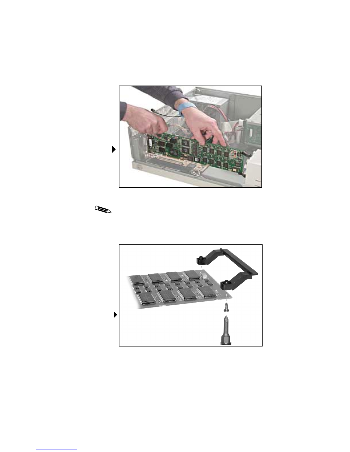
Unpacking the board
Remove the Md4/PCV board slowly from its package and
protective sleeve to guard against electrostatic discharge.
6
Static electricity can damage the board. When touching the
board or parts of the motherboard, take these precautions:
• Wear an antistatic wrist strap.
• Always keep one hand touching a bare metal surface
to provide grounding.
• If you can’t perform a step with one hand, use both and
return one hand occasionally to the metal surface.
To prepare for board installation
1. Turn off the power to your computer.
Leave the computer plugged into a grounded power
outlet. This allows the power cord to serve as a ground
for the computer.
If you leave the computer turned on, you might suffer
electric shock or cause damage to both the computer
components and the Md4/PCV board.
2. Remove the cover from the computer according to the
manufacturer’s instructions.
Page 17

Preparing for Board Installation | 7
3. Determine which board will support VGA display:
• The Md4/PCV board (See below.)
• Another VGA board (See page 8.)
To install multiple Md4/PCV boards, see page 14 for
instructions.
Using the Md4/PCV board to support VGA display
When you use the Md4/PCV board to support VGA display, you
set the board as the VGA console. This enables the Md4/PCV
board to support VGA display and run the DOME Windows
driver simultaneously.
To set the board as the VGA console
1. Remove the existing VGA board from your computer.
2. Enable VGA mode on the Md4/PCV board. (See page 8.)
3. Attach the VGA ribbon cable to the Md4/PCV board. (The
connector is keyed to ensure correct installation.)
4. Install the Md4/PCV board. (See page 11.)
Attaching a VGA ribbon cable
Page 18
| Installing the Board and Driver
Supporting VGA with another board
To support VGA with another board, you must disable VGA
mode on the Md4/PCV board. (See page 10
When you install the Md4/PCV board in a computer that has an
existing VGA board, only one of the boards can support the
Windows NT operating system. You can run Windows NT on
either board, but you cannot run Windows NT on both boards
simultaneously.
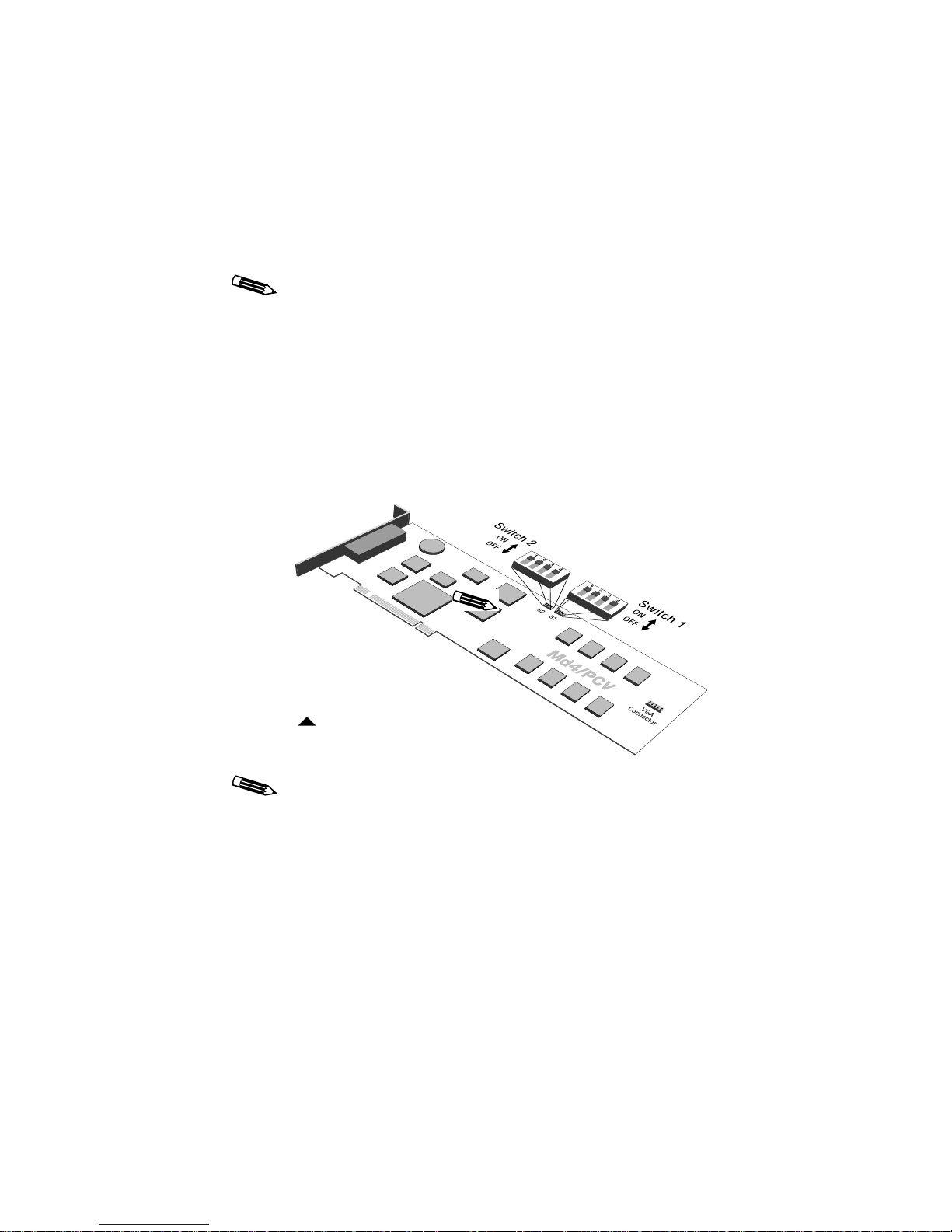
Enabling or disabling VGA mode
Set the DIP switches, located near the top center of the Md4/PCV
board, to enable or disable VGA mode.
8
.)
DIP switches on the Md4/PCV board
Disable VGA mode if you are using the Md4/PCV board
with an existing VGA board or with multiple Md4/PCV
boards. Enable VGA mode if you are using the VGA port
of the Md4/PCV board.
Page 19

Preparing for Board Installation | 9
This table shows the setting options for DIP switch S1. Change
these settings to enable or disable VGA mode, as described in the
following sections.
DIP Switch On Off
1 VGA disabled VGA enabled
2 EPROM enabled
3 Standard Md4/PCV
a
EPROM disabled
a
VGA boot messages appear on
a
high-resolution monitor
4 Select low BIOS
a. Indicates factory setting.
a
Select high BIOS
Use switch S2 to select monitor resolution when you enable
the option to display VGA boot messages on a high-resolution
monitor. For more information, see “To enable VGA boot
messages on a high-resolution monitor” on page 10.
To enable VGA mode
Slide the DIP switches on switch S1 into the positions shown in
this table.
DIP Switch Setting
1 OFF
2ON
3ON
4ON
Page 20

10 | Installing the Board and Driver
To disable VGA mode
Slide the DIP switches on switch S1 into the positions shown in
this table.
DIP Switch Setting
1ON
2 OFF
3ON
4ON
The default settings for switch S2, located to the left of switch S1,
are all OFF.
To enable VGA boot messages on a
high-resolution monitor
Set DIP switch 3 on switch S1 to OFF and DIP switches 2 and 4 to
ON. This table describes the settings.
DIP Switch Setting Note
1 OFF If OFF, the Md4/PCV board acts as the
VGA device, but the output is directed to
the high-resolution screen instead of the
VGA connector.
ON If ON, the Md4/PCV board copies text
from the V GA device to the high-resolution
monitor.
2 ON Must be ON.
3 OFF Lets you direct VGA boot messages to the
high-resolution monitor.
4 ON Must be ON.
Page 21
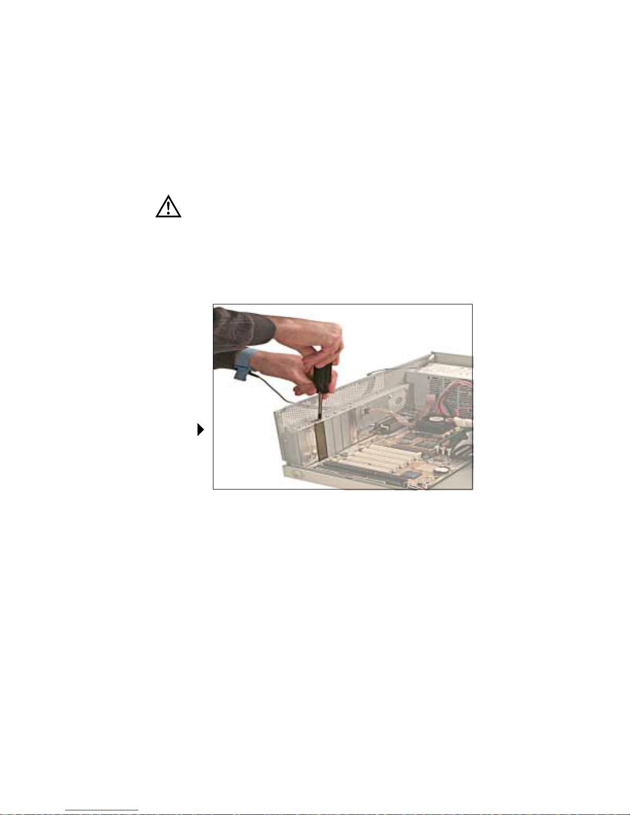
Installing the Md4/PCV Board
This section describes how to install the Md4/PCV board
in a PC.
Static electricity can damage the board. Wear an antistatic
wrist strap or touch one hand to a bare metal surface on the
power supply to discharge static electricity.
To install the board
1. Remove the blank bracket from the back of any
available PCI slot.
Installing the Md4/PCV Board | 11
Removing
a bracket
Page 22
12 | Installing the Board and Driver
2. Insert the Md4/PCV board firmly into the slot.
Installing an
Md4/PCV board
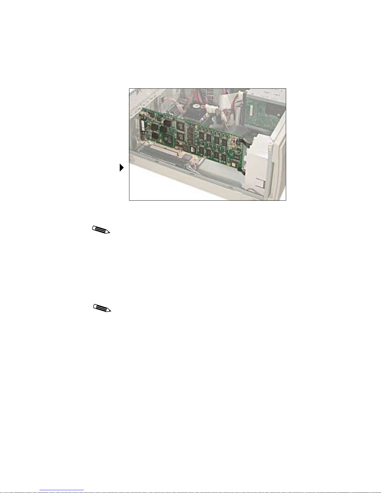
If a retainer on the board prevents it from fitting in the slot,
remove the two screws that attach the retainer to the board,
and remove the retainer.
Removing
the retainer
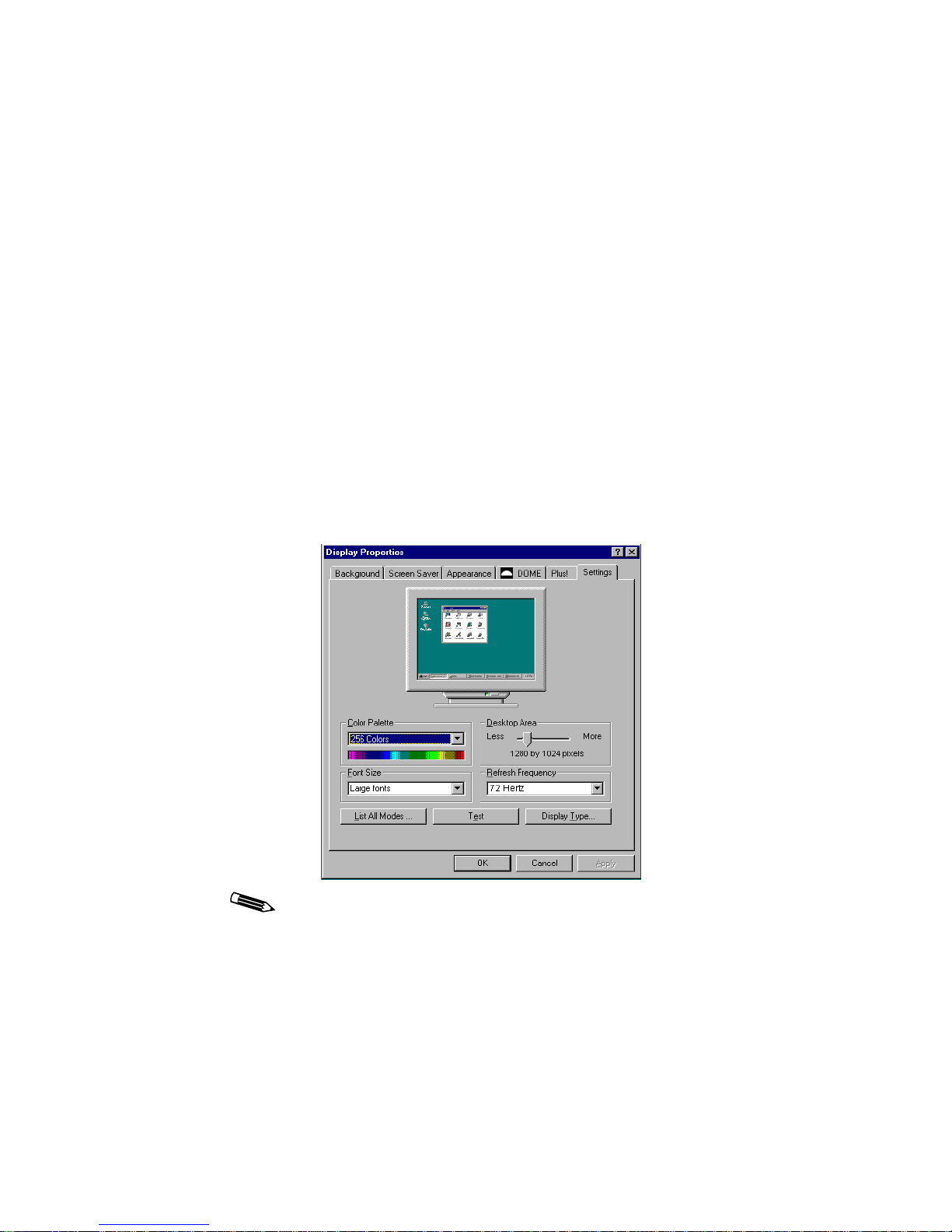
Page 23
Installed
Md4/PCV board
Installing the Md4/PCV Board | 13
3. Make sure the board connector pins are aligned with the slot.
4. Secure the mounting bracket with the bracket screw.
If you are not using the Md4/PCV board to support
VGA, go to step 8.
5. Remove a blank bracket from the back of the slot you choose
for the VGA output.
6. Insert the VGA bracket and secure the mounting bracket
with the bracket screw.
7. Attach the VGA monitor to the 15-pin connector.
Repeat steps 1–4 for each Md4/PCV board you want
to install.
8. Replace the system unit cover.
Page 24

14 | Installing the Board and Driver
To install multiple boards
Repeat the installation instructions that start on page 11 for
each board.
Remember these tips when installing multiple boards:
• The Windows NT driver version 4.4.0 supports up
to 8 Md4/PCV boards (16 screens).
• Each board requires less than 5 amps of +5V.
• You can install as many Md4/PCV boards as your
system’s power supply and available PCI slots can
support. (Windows 2000 only).
• You cannot mix DOME board types; additional boards must
be Md4/PCV boards (Windows NT only).
• You must disable VGA mode on all but one Md4/PCV board
if multiple boards are in use. (See page 10.)
Page 25

Connecting the Monitors
Once the Md4/PCV board is installed in your computer,
connect the monitors to the board with the cable provided.
For the Md4/PCV2 board, the cable has two branches, each
with three connectors.
Use this table to attach the cables to the appropriate output
signals on the two monitors.
Monitor Cable Label Output Signal
Monitor 1 VIDEO1 Monitor 1 video
Connecting the Monitors | 15
VSYNC1 Monitor 1 vertical sync
HSYNC1 Monitor 1 horizontal sync
Monitor 2 VIDEO2 Monitor 2 video
VSYNC2 Monitor 2 vertical sync
HSYNC2 Monitor 2 horizontal sync
If you are using only one monitor, use the settings for Monitor 1.
To connect the monitors to the board
1. Attach the D-shell connector to the Md4/PCV board.
2. Secure the connection with the screws on the connector.
3. Attach each of the output cables to the appropriate BNC
terminal on your monitor.
Refer to your monitor documentation for more information
about the connector assignments on your monitor.
4. Repeat step 2 for each monitor you want to connect to the
Md4/PCV board.
Page 26

16 | Installing the Board and Driver
To finish the installation
Install the DOME Windows driver after you install the
Md4/PCV board to finish the installation.
• To install the Windows NT driver, see page 17.
• To install the Windows 2000 driver, see page 40.
Page 27
Installing the PCV Windows NT 4.0 Driver | 17
Installing the PCV Windows NT 4.0 Driver
This procedure assumes that the Windows NT 4.0 operating
system is already installed on your system. If it is not, refer to the
Microsoft Windows NT 4.0 documentation.
To install the driver
1. Turn on the computer and select Windows NT
Workstation Version 4.00 [VGA mode].
2. Log on as administrator.
You need administrator privileges to change the
display settings.
3. Select Start -> Settings -> Control Panel ->
Display icon -> Settings tab.
The Settings tab appears.
This illustration shows the Settings tab only. The DOME tab
does not display until you install the driver.
Page 28

18 | Installing the Board and Driver
4. Click Display Type….
The Display Type dialog box appears.
5. Click Change… in the Adapter Type section of the
dialog box.
The Change Display dialog box appears.
6. Click Have Disk….
The Install From Disk dialog box appears, containing
this field:
Copy manufacturer’s files from:
A:\
7. Insert the WINDRIVER CD and browse to the
WinNT4\MdxPCX\mdxpcx.4.4.
(where
x.yyy
8. Find and select the oemsetup.inf file, and click Open….
9. The Change Display dialog box appears with these choices:
x.yyy
directory
denotes secondary version numbers).
DOME imaging systems Md4/PCV
DOME imaging systems Md4/PCX
DOME imaging systems Md5/PCX
10. Select DOME imaging systems Md4/PCV, and click OK.
The Third-party Drivers dialog box appears, prompting you:
Do you wish to proceed?
11. Click Yes.
A progress bar appears.
The drivers were successfully installed.
12. Click OK.
13. Click Close on the Display Type dialog box and on the
Display Properties dialog box.
Page 29

Installing the PCV Windows NT 4.0 Driver | 19
This message appears:
Do you want to restart your computer now?
14. Click Yes.
When the computer restarts, it prompts you to select an
operating system.
15. Select Windows NT Workstation Version 4.00 [VGA mode],
and then configure your display settings. (See page 20.)
Page 30

20 | Installing the Board and Driver
Configuring Display Settings on Windows NT
After you install the board and driver, set the display resolution
and refresh rate. You can then use the DOME tab to change
display properties.
To set the display resolution and refresh rate
1. Log on as administrator.
The Invalid display settings dialog box displays.
2. Click OK.
The Settings tab appears. (See page 17.)
3. Click List All Modes….
The Detected Adapter dialog box appears.
Sample Detected
Adapter dialog box
The dialog box on your screen displays the values that exist
in your binary .cfg file, which may be different from the
values displayed in this illustration. For more information
on editing these values, see “Customizing Sync Parameters
on Windows NT” on page 73.
4. Select the resolution and refresh rate, and click OK.
Page 31

Configuring Display Settings on Windows NT | 21
5. Click Test.
Your monitor(s) must be connected to test the resolution
and refresh rate.
The Testing Mode dialog box appears with this message:
The new mode will be tested. Your graphics adapter
is set to the new mode temporarily so that you can
determine whether it works properly. Click OK and
then wait 15 seconds.
6. Click OK.
A test bitmap appears.
The Testing Mode dialog box appears, prompting you:
Did you see the test bitmap properly?
7. Click Yes if the test bitmap displayed correctly or
No if it didn’t.
If No, the Testing Mode dialog box appears, prompting you
to try different settings for your display. Click OK. Repeat
steps 3–7 to perform the test with a different resolution.
8. Select Large Fonts in the Font Size field (optional).
Selecting Large Fonts on the Settings tab does not make a
significant difference in font size at very high resolutions.
The DOME driver installs extra-large font options in your
C:\dome\tools
directory. To add those fonts to your
display properties, follow the instructions for “DOME large
fonts” on page 30.
9. Click OK.
The display resolution is now set properly for the
Md4/PCV board.
This message appears:
Do you want to restart your computer now?
10. Click No.
Page 32

22 | Installing the Board and Driver
You can now change your display properties using
the DOME tab.
11. Select Start -> Settings -> Control Panel ->
Display icon -> DOME tab.
A dialog box prompts you to choose a configuration file
(because the system is currently in VGA mode).
12. Click Open to use the default configuration file (md4pcv.cfg)
on your system.
The DOME tab appears. (See page 23.)
You can make several changes to your display settings at
one time. For more information, see “Using the DOME tab
to change display properties” on page 23.
13. Click OK or Apply when you have selected all the new
settings and want to activate them.
This message appears:
Do you want to restart your computer now?
14. Click Yes.
The computer prompts you to select an operating system.
15. Select Windows NT Workstation 4.00, then change your
display settings. (See page 23.)
Page 33

Configuring Display Settings on Windows NT | 23
Using the DOME tab to change display properties
You can use the DOME tab to change display properties such as
resolution and refresh rate, screen configuration, palette options,
monitor preferences, and driver options. See the following
sections for more information on these display properties.
To use the DOME tab
1. Select Start -> Settings -> Control Panel ->
Display icon -> DOME tab.
The DOME tab appears.
2. Select the desired display properties, then click Apply -> OK.
Restart your computer to display the changes.
Page 34

24 | Installing the Board and Driver
To use the DOME tab online help
The Windows NT driver provides online context-sensitive help
for the DOME tab. You can access the help in either of two ways:
• Click the question mark (?) button on the title bar, then click
the area of the DOME tab with which you need assistance.
• Move the cursor to the area with which you need assistance,
then press <F1>.
Setting the screen configuration
In the Configuration field of the DOME tab, click the screen
number and orientation. Then click Apply or OK.
Remember these tips when installing multiple boards:
• The NT driver (version 4.4.0) supports up to eight boards
(16 screens) of the same type.
• You cannot mix DOME board types.
• Screen zero (0) is the upper-leftmost screen. The rest of the
screens are counted down and then across.
For example, with four screens in a 2 x 2 pattern, the screens
are numbered as follows:
Screen 0, upper left Screen 2, upper right
Screen 1, lower left Screen 3, lower right
• The screens are assigned to the boards in the order in which
the boards are found on the bus. For example, if the first board
is a dual-headed board, it controls screens zero (0) and one (1).
Page 35

Configuring Display Settings on Windows NT | 25
Changing the resolution and refresh rate
In the Resolution and Refresh Rate field of the DOME tab,
adjust the display resolution and refresh rate to suit the
particular needs of your application.
To change the resolution and refresh rate
1. Highlight the desired resolution and refresh rate.
2. Click Apply or OK.
This dialog box appears, indicating that the new settings are
about to be tested.
3. Click OK to start the test.
Another dialog box appears, indicating that the new settings
are being tested.
4. Click OK within 15 seconds to accept the new settings.
Click Cancel or ignore the message to revert to the
original settings.
Page 36

26 | Installing the Board and Driver
Setting palette options
In the Palette Options field of the DOME tab, use the
pull-down menu to select a palette option. (See page 23.)
Then click Apply or OK.
With the Windows NT 4.0 operating system, the Md4/PCV
board supports these palettes:
• Dynamic gray
• Nonlinear static gray
• Static gray
This illustration shows the features of the grayscale palettes.
Grayscale palettes
You can set a palette from the DOME tab in the Display
Properties dialog box.
Page 37

Configuring Display Settings on Windows NT | 27
Dynamic gray palette
The dynamic gray palette reserves the first and last 10 entries in
the palette for the Windows NT operating system, so an application cannot manipulate them. You can, however, manipulate the
middle 236 entries.
Your application can create a 256-entry gray ramp in any 8-bit
driver with the SetSystemPaletteUse() Windows API (application program interface) call, but doing so causes all icons to be
redrawn in black and white.
The dynamic gray palette accommodates gray-mapped Windows
colors for the first and last 10 palette entries.
Nonlinear static gray palette
The nonlinear static gray palette sets the first and last 10 palette
entries to gray-mapped Windows colors. The middle 236 entries
are ramped in ascending order, excluding the first and last 10
palette entries. Windows applications that use the first and last 10
palette entries as Windows colors display correctly on the screen.
Although the nonlinear static gray palette provides correct
colors for applications using the Windows palette, colors display
incorrectly if the application assumes that a static palette is
always ramped.
Application colors display incorrectly in both static palette
modes if the application assumes all 8-bit framebuffers have
palettes that can be set.
Applications cannot set palette types. Applications must read the
palette from the operating system and use it when drawing
directly to the framebuffer.
Static gray palette
The static gray palette provides 256 shades of gray in a linear
static palette. This frees the entire grayscale ramp for applications
by not reserving the first and last 10 palette entries for icons and
other standard Windows graphics.
Page 38

28 | Installing the Board and Driver
The static gray palette does not provide gray-mapped Windows
colors for the first and last 10 palette entries. Because the framebuffer assumes the Windows palette is in use, applications that
draw directly to the framebuffer display incorrectly. For example, icons and button bitmaps may display in black and white.
Setting monitor preferences
In the Monitor Preferences field of the DOME tab, select the box
next to Pedestal. Then click Apply or OK.
For more information, refer to the documentation for your
monitor.
Setting driver options
The Disable DirectDraw driver option has specific conditions
that might affect your display. Be sure to read the following
sections before you choose this option.
To disable DirectDraw
In the Driver Options field of the DOME tab, select the box next
to Disable DirectDraw. Then click Apply or OK.
DirectDraw and multiheaded support
DirectDraw is an API that allows direct manipulation of the video
display. DirectDraw applications expect the screen to be represented as a single element. If you are using multiple Md4/PCV
screens, then more than one screen represents the desktop.
With multiple displays representing the desktop, DirectDraw
applications cannot access the entire desktop and may not
work properly.
DirectDraw limited screen size
Under the Windows NT 4.0 operating system, Build 1381,
DirectDraw supports screen sizes only up to 2048 x 2048 pixels.
DirectDraw applications may not function properly with bigger
screen sizes.
Page 39

Configuring Display Settings on Windows NT | 29
Microsoft is aware of this problem and plans to correct it in a
future release of Windows NT. Although DOME has made
efforts to provide whatever support possible within this limitation, DOME cannot ensure DirectDraw compatibility with either
multiple screens or a screen size greater than 2048 x 2048 pixels.
Page 40

30 | Installing the Board and Driver
Additional Configuration Options on Windows NT
You can configure the DOME Windows NT driver to modify
screen appearance, relocate dialog boxes across screens, and
activate a screen saver.
DOME large fonts
The Windows NT 4.0 driver uses standard Windows fonts. The
DOME driver supplements these fonts with three large fonts that
support high-resolution display. The DOME Windows NT 4.0
driver installs those fonts in the C:\dome\tools directory.
Installing DOME large fonts does not automatically increase the
size of your cursor. For more information, see “To increase the
cursor size” on page 31.
To install DOME large fonts
1. Double-click My Computer -> C: -> DOME -> Tools.
A list of files appears.
2. Double-click the desired font:
• DOME large
• DOME extra large
• DOME extra extra large
3. Close all applications and windows.
4. Restart your computer.
5. Select Start -> Settings -> Control Panel ->
Display icon -> Appearance tab.
The Appearance tab appears.
6. Click the Scheme pull-down arrow, and select the
desired font.
7. Click OK.
Page 41

Additional Configuration Options on Windows NT | 31
To uninstall DOME large fonts
1. Double-click My Computer -> C: -> DOME -> Tools.
A list of files appears.
2. Double-click WinStand.reg.
3. Click OK.
4. Close all applications and windows.
5. Restart your computer.
6. Select Start -> Settings -> Control Panel ->
Display icon -> Appearance tab.
7. Click the Scheme pull-down arrow, and select
Windows Standard.
8. Click OK.
To increase the cursor size
1. Select Start -> Settings -> Control Panel ->
Mouse icon -> Pointers tab.
The Pointers tab appears.
2. Click the Scheme pull-down arrow, and select
Windows Standard (extra large).
3. Click OK.
4. Close the Control Panel dialog box.
To return to the standard cursor size, follow steps 1–4 of
this procedure, and select Windows Standard from the
Scheme pull-down menu.
Page 42

32 | Installing the Board and Driver
Customizing item and font size
Use the Display Properties dialog box to adjust both your
system-level and application-level font sizes to compensate for
high-resolution display. You can also customize font appearance
and icon, menu, and title bar size.
This table provides recommended font and icon sizes for
high-resolution displays.
This
selection…
Controls font and
size of this item…
Its default
settings
are…
Its
recommended
Md4/PCV
settings are…
Active Title Bar Active window title
bar
Item size: 18
Font size: 8
Item size:
Font size: 10 or
a
--
12
Icon Icons on the desktop
Menu All menus, both
system- and
application-level
Message Box All message box text Item size:
Tool Tip All tool tip text, both
system- and
application-level
a. The item size adjusts automatically if the font size changes.
b. If the item or font size is too large, the icon and text may be cropped.
If this occurs, adjust the icon spacing by right-clicking on the desktop
and choosing Line Up Icons or Arrange Icons. You can also change
icon spacing by choosing Icon Spacing (Horizontal) and Icon Spacing
(Vertical), and adjusting the size setting to a larger number. (The default
spacing is 43.)
b
Item size: 32
Font size: 8
Item size: 18
Font size: 8
n/a
Font size: 8
Item size: 18
Font size: 8
Item size:48
Font size: 10
Item size:
b
-Font size: 10 or
12
Item size: n/a
Font size: 10 or
12
Item size: -Font size: 10 or
12
Page 43

Additional Configuration Options on Windows NT | 33
DOME DlgFix software
The DOME DlgFix software automatically relocates all dialog
boxes to the upper-left screen, preventing dialog boxes from
splitting across screens.
Dialog box splits across screens when DlgFix is not running
Dialog box displays in upper-left screen when DlgFix is running
Page 44

34 | Installing the Board and Driver
The DOME DlgFix software installs automatically during
Windows NT 4.0 driver installation.
Limitations of DlgFix
Because of limitations in the Windows NT operating system,
DlgFix
the startup programs; logon dialog boxes are still split
between screens.
cannot modify dialog box locations until you run
To run DlgFix
Type C:\dome\tools\DlgFix at the DOS prompt.
The DOME DlgFix icon appears on your taskbar to indicate that
DlgFix
is running.
To add DlgFix to the startup menu
Type C:\dome\tools\DlgSetup at the DOS prompt.
After you type this command, DlgFix will automatically start
each time you boot your computer.
To uninstall DlgFix
Type C:\dome\tools\DlgUnins at the DOS prompt.
Your system may experience a slight degradation in performance
while running DlgFix. If you find system performance unacceptable, uninstall the software as indicated above.
Page 45

Additional Configuration Options on Windows NT | 35
DOME DPMS Screen Saver
Display Power Management Signaling (DPMS) provides a standard way to manage the power used by a display monitor. With
DPMS, you can shut off the video signal to the monitor when it is
not in use, thereby extending the life of your monitor’s CRT and
reducing its power consumption.
The DOME DPMS Screen Saver for Windows NT offers a powerful and flexible way to increase the life of your monitor and
decrease its power consumption.
How the screen saver works
Like other Windows screen savers, the DOME DPMS Screen
Saver is invoked after the system is idle for a specified number of
minutes. Unlike other screen savers, however, the DOME DPMS
Screen Saver does not display anything on the monitor itself.
Rather, it launches another screen saver that you select to protect
the display. Then, after a predetermined number of minutes, it
uses DPMS to shut off the video power to the display.
There are two delay periods before DPMS is invoked.
• First, the standard screen saver delay from the last user input
until the screen saver launches.
• Second, from the time the screen saver launches to the moment
DPMS shuts off the video power to the monitor. After this
delay, DPMS places the monitor in power-off mode.
The DOME DPMS Screen Saver allows you to select the other
screen saver to use before it invokes power-off mode. It also
allows you to specify up to four periods during the day and
different settings for if or when power-off mode is invoked
during each period.
Page 46

36 | Installing the Board and Driver
To select the DOME DPMS Screen Saver
1. Select Start -> Settings -> Control Panel -> Display icon ->
Screen Saver tab.
The Screen Saver tab appears.
2. Select DOME DPMS Screen Saver from the list of
screen savers.
3. Set the Wait: field with the time (in minutes) that must
elapse before the first screen saver appears.
Page 47

Additional Configuration Options on Windows NT | 37
To set up the DOME DPMS Screen Saver
1. Click Settings….
This dialog box appears.
2. Select a Screen Saver from the list of available screen savers.
The screen saver you select appears on your monitor before
DPMS power-off mode is invoked. You can select any of the
other installed Windows screen savers to protect the monitor
during that time. The Settings and Preview buttons enable
you to adjust the screen saver settings and see a sample of
each screen saver.
Page 48

38 | Installing the Board and Driver
You can create up to four distinct periods throughout the
day, with different DPMS settings for each period. Continue
this procedure to set each time period.
3. Set the start time in the Starting at: field.
Use a 24-hour time format, such as 16:30 to indicate 4:30 P.M.
This determines if or when power-off mode is invoked for up
to four different periods of the day.
Leave the start time for a period blank if you don’t want to
use it.
4. Enter the number of minutes of additional inactivity (after
the first screen saver displays) that must elapse before the
monitor is placed in power-off mode in the Invoke DPMS
after: field.
5. If desired, select Wake at start of period to force the monitor
to wake up if it is in power-off mode at the start of the period.
6. If desired, select Never sleep during this period to prevent a
switch to power-off mode during the period.
7. Click OK to keep your settings or Cancel to discard them.
The Display Properties dialog box appears.
8. Click OK.
Remember these tips when you set the screen saver:
• The two delay periods are cumulative. If it takes 15 minutes
of inactivity for the DOME DPMS Screen Saver to start, and
there is a 30-minute delay until power-off mode is invoked
for the current time period, power-off mode starts after a
total of 45 minutes of inactivity.
• After the monitor is in power-off mode for a long time, it can
take up to 30 minutes to reach optimal performance when
the video power is turned on again. To ensure that the
monitor performs optimally when in use, use the DOME
DPMS Screen Saver to force the monitor to wake up before
expected periods of heavy use.
Page 49

Additional Components for Windows NT | 39
Additional Components for Windows NT
These are additional DOME software components that run on
Windows NT systems using the Md4/PCV board.
Dynamic-link library
The mdpcint.dll dynamic-link library (DLL) is a group of
functions that can link to DOME applications, such as the DOME
Image-Processing Library and Calibration TQA.
The DLL installs automatically when you load the Windows NT
4.0 driver.
DIMPL library
The DOME Image-Processing Library (DIMPL) provides a group
of functions for image manipulation. The DIMPL library uses the
DirectDraw facilities in the Windows NT 4.0 operating system
and works cooperatively with the DOME driver.
DimplX control
The DimplX control is the ActiveX interface to the DIMPL library.
It provides an easy-to-use interface to the powerful DIMPL functions. It also uses the DirectDraw facilities in the Windows NT 4.0
operating system.
Page 50

40 | Installing the Board and Driver
Calibration TQA
To run the DOME calibration software on a Windows NT system,
use only Calibration TQA™ 2.0.3 or later software.
You can run Calibration TQA 2.0.3 or later on a system that
includes both DOME and other brands of boards.
Do not change Windows display settings while Calibration TQA
is running. Calibration TQA and other mdpcint.dll-reliant
applications behave unpredictably if you make changes while
the application is active.
Page 51

Installing the PCV Windows 2000 Driver | 41
Installing the PCV Windows 2000 Driver
This procedure assumes the Windows 2000 operating system
is already installed on your computer. If it is not, refer to the
Microsoft Windows 2000 documentation.
Read this important information before you install the DOME
Windows 2000 driver:
• Install all DOME boards before you install the DOME
driver. See “Installing the Md4/PCV Board” on page 11
for instructions.
• Restart your computer after installing the boards, and then
install the DOME driver for each board. See “To install the
driver for an additional board” below for instructions.
To install the driver
1. Turn on the computer, and start Microsoft Windows 2000
Professional.
2. Log on as administrator.
The Systems Settings Change dialog box may appear. If it
does, click Yes to restart the computer, and log on with
administrator privileges.
3. Insert the WINDRIVER CD and browse to find the
win2k\MdXPCX
Setup.exe application.
The Setup.exe file is an InstallShield Wizard that
guides you through the installation process.
directory. Then double-click the
Page 52

42 | Installing the Board and Driver
The initial display driver installation dialog box appears.
4. Proceed through the license agreement and readme files.
The Setup Type dialog box appears for each Md4/PCV
board installed.
Page 53

Installing the PCV Windows 2000 Driver | 43
5. Select either One or Two for the number of displays
connected to your Md4/PCV board. Click Next.
6. Click Yes on the Digital Signature Not Found dialog box.
This dialog box appears for each display you install.
The End of Driver Installation dialog box appears
upon completion.
7. Select Yes, I want to restart my computer now, and
click Finish.
The Md4/PCV driver loads upon system restart.
Page 54

44 | Installing the Board and Driver
To modify or update an existing configuration
1. Insert the WINDRIVER CD and browse to find the
win2k\MdXPCX directory.
2. Double-click Setup.exe.
The DOME Hardware and Software Maintenance dialog
box appears.
3. Choose Modify, and click Next.
Modify an existing configuration if you are adding a new
Md4/PCV board, adding another display to a board that is
already installed, or if you are updating your system with a
subsequent MdX/PCX release.
Page 55

Installing the PCV Windows 2000 Driver | 45
The Setup Type dialog box appears.
4. Select one of the following options:
• Update Md4/PCV Driver for Board 1
• Add a Display for Board 1 to add a second display to an
existing board installed as a single head.
5. Click Next.
The Digital Signature Not Found dialog box appears for
each display installed.
6. Click Yes to continue the installation.
The End of Driver Installation dialog box appears
upon completion.
7. Select Yes, I want to restart my computer now, and
click Finish.
8. Click Finish to close the InstallShield Wizard.
The Md4/PCV driver loads upon system restart.
Page 56

46 | Installing the Board and Driver
To install the driver for an additional board
1. Turn off the power to your computer.
If you leave the computer turned on, you could suffer
electric shock or cause damage to both the computer
components and the Md4/PCV board.
2. Install the board, and follow the installation steps on
pages 41–43.
Make sure VGA is disabled on additional Md4/PCV boards
you install.
3. Turn on your computer, select VGA mode, and log on as
administrator.
The Windows 2000 operating system recognizes the new
hardware device. The Digital Signature Not Found dialog
box appears.
4. Click Yes.
5. Insert the WINDRIVER CD, and click Browse… to open the
win2k\MdXPCX\mdxpcx 5.0.x.
yyy
directory (where x.
yyy
denotes secondary version numbers).
6. Click Open.
The Files Needed dialog box appears.
7. Click OK.
If you’ve installed a... Then... The next step is to...
Single-headed board The installation is
complete.
Dual-headed board The installation is
not complete.
Enable your display
and set the resolution.
(See page 49.)
Modify your display
configuration. (See
page 47.)
Page 57

Installing the PCV Windows 2000 Driver | 47
To modify the display configuration
for a dual-headed board
1. Browse to the win2k\MdXPCX directory, and double-click
Setup.exe.
This dialog box appears.
2. Select Modify, and click Next.
Modify an existing configuration if you are adding a new
Md4/PCV board, adding another display to a board that is
already installed, or if you are updating your system with a
subsequent MdX/PCX release.
The Setup Type dialog box appears for each Md4/PCV board
you have installed.
Page 58

48 | Installing the Board and Driver
3. Select one of these options, then click Next:
• Update Mdx/PCV Driver for Board x for boards that are
already configured.
• Add a Display for Board x for the newly installed board,
where x is 2 if you are adding the second board, 3 if you
are adding the third board, and so on.
4. If you are adding a display, click Yes to indicate that you
want to install the second display.
The Digital Signature Not Found dialog box appears.
5. Click Yes.
The Digital Signature Not Found dialog box appears for
each display installed.
The End of Driver Installation dialog box appears.
6. Select Yes, I want to restart my computer now, and
click Finish.
7. Click Finish to close the InstallShield Wizard.
The Md4/PCV driver loads upon system restart.
Page 59

Installing the PCV Windows 2000 Driver | 49
To enable displays and set the display resolution
1. Turn on your computer.
2. Log on as administrator.
3. Right-click the desktop, and select Properties -> Settings.
4. Click the Display list and select Default Monitor on
Md4/PCX, Md4/PCV, or Md5/PCX.
5. Select Advanced -> Adapter -> List All Modes.
6. Highlight the desired resolution, and click OK.
7. Select Apply -> OK from the Default Monitor on
DOME Md4/PCX, Md4/PCV, or Md5/PCX Properties
dialog box.
8. Select Extend my Windows desktop onto this monitor, and
click Apply.
This message may appear:
Windows will now apply your new desktop settings.
The original desktop will be restored if the
settings are not applied correctly.
9. If it does, click OK to accept the new settings, or Cancel to
revert to the original settings.
If you have installed two or more displays, enable them as
described in steps 3–9.
Page 60

50 | Installing the Board and Driver
Configuring Display Settings on Windows 2000
After you install the board and driver and set the default monitor
and refresh rate, you can change the resolution and refresh rate
or any other configuration options.
Use this tab... To set the default monitor and refresh rate for...
DOME tab Displays attached to the Windows 2000 desktop
Properties ->
Settings tab
Displays not attached to the Windows 2000 desktop
The Windows 2000 operating system renumbers and reassigns
screens as they are added to the configuration. Set resolutions
or preferences only after all boards and screens are installed.
Then restart your system to make sure the screen assignments
are stable.
Determining screen assignments
Use the Identify button in the Settings tab to see which screens
are associated with which boards.
Page 61

Configuring Display Settings on Windows 2000 | 51
Using the DOME tab to change display properties
You can change display properties (such as the resolution and
refresh rate, monitor preferences, driver options, palette options,
custom syncs) with the DOME tab after the display is attached to
the Windows 2000 desktop.
To change display properties
1. Log on with administrator privileges.
2. Right-click the desktop, and select Properties ->
Settings tab.
The Settings tab appears.
3. Select Default Monitor on DOME Md4/PCX, Md4/PCV or
Md5/PCX from the Display box.
Make sure the Extend my Windows desktop onto this
monitor box is checked.
4. Select Advanced -> DOME tab to select a resolution and
refresh rate.
Page 62

52 | Installing the Board and Driver
The DOME tab appears.
To change the resolution and refresh rate
1. Select a resolution and refresh rate from the DOME tab, and
click Apply.
When you use the DOME tab to set the resolution and
refresh rate for one of the displays of a dual-headed DOME
display board, the second display will assume the same
resolution and refresh rate.
The DOME Display Resolution dialog box appears.
Page 63

Configuring Display Settings on Windows 2000 | 53
2. Click OK within 15 seconds to accept the new settings.
Ignore the message to revert to the original settings.
The resolution changes on both installed screens, and a
message appears prompting you to accept or cancel the
new resolution.
3. Click OK to set this resolution, or Cancel to return to the
DOME tab.
If you select OK, this message appears.
4. Click OK. You can now use the display.
To set monitor preferences
To enable Pedestal, select Pedestal on the DOME tab. Refer to
your monitor documentation for more information.
To set driver options
To disable DirectDraw, select Disable DirectDraw on the
DOME tab.
Page 64

54 | Installing the Board and Driver
Setting palette options
DOME palette options must coordinate with the primary
display. All monitors must be set to either palette devices or
non-palette devices.
Palette Device Non-Palette Device
• Dynamic gray • Static gray
This illustration shows the assignment of values on the
grayscale palettes.
• Nonlinear static gray
All DOME boards that support multiple displays support
differing palette options on multiple screens attached to the
same board.
Grayscale palettes
Page 65

Configuring Display Settings on Windows 2000 | 55
Palette options with multiple displays
The Microsoft Developer’s Network (MSDN) SelectPalette
and RealizePalette functions work across all monitors if
the primary monitor is palettized. The palettes of all palettized
devices are synchronized. If, however, the primary monitor is
not palettized, SelectPalette and RealizePalette select
the palette into the background, and palettized devices are
not synchronized.
Desktop icons
The palette specifications of the primary display determine
how desktop icons are drawn. For example, the desktop icons
appear gray in a color screen if the primary display is set to a
gray palette.
The following table defines the palette options that work on
primary and secondary displays. Column 3 indicates whether
the listed palette combinations (in columns 1 and 2) work.
Page 66

56 | Installing the Board and Driver
Primary Display Secondary Display Combination OK?
Commodity board at
Dynamic gray No
16 bits per pixel (bpp)
Commodity board at
Static gray Yes
16 bpp
Commodity board at
Nonlinear gray Yes
16 bpp
Commodity board at
True color Yes
16 bpp
Dynamic gray Commodity board at
Yes
16 bpp
Dynamic gray Dynamic gray Yes
Dynamic gray Static gray No
Dynamic gray Nonlinear static gray Yes
Dynamic gray True color Yes
Dynamic gray Pseudocolor Yes
Static gray Commodity board at
Yes
16 bpp
Static gray Dynamic gray No
Static gray Static gray Yes
Static gray Nonlinear static gray Yes
Static gray True color No
Static gray Pseudocolor No
Nonlinear static gray Commodity board at
Yes
16 bpp
Nonlinear static gray Dynamic gray No
(cont.)
Page 67

Configuring Display Settings on Windows 2000 | 57
Primary Display Secondary Display Combination OK?
Nonlinear static gray Static gray Yes
Nonlinear static gray Nonlinear static gray Yes
Nonlinear static gray True color Yes
Nonlinear static gray Pseudocolor No
True color Commodity board at
Yes
16 bpp
True color Dynamic gray No
True color Static gray Yes
True color Nonlinear static gray Yes
True color True color Yes
True color Pseudocolor Yes
Pseudocolor Commodity board at
Yes
16 bpp
Pseudocolor Dynamic gray Yes
Pseudocolor Static gray No
Pseudocolor Nonlinear static gray Yes
Pseudocolor True color Yes
Pseudocolor Pseudocolor Yes
Page 68

58 | Installing the Board and Driver
To set custom syncs
Right-click the desktop, and select Properties -> Settings tab ->
Advanced -> DOME tab -> Custom Mode.
The Custom Mode dialog box appears.
The Custom Mode dialog box enables you to do the following:
• Customize modes
• Create modes
• Remove modes
• Restore original modes (configuration file)
The mode changes you make are stored in a .dom file, and
the driver loads the .dom file at boot time. See “Restoring the
original modes” on page 61 for more information.
Page 69

Configuring Display Settings on Windows 2000 | 59
To customize or add modes
1. If necessary, connect a monitor to your installed
DOME board.
2. Return to the Settings tab and select the test display from
the Display list.
3. Make sure Extend my Windows desktop onto this monitor
is selected, and click Apply.
The display extends to the selected test display.
4. Select Advanced -> DOME tab -> Custom Mode.
Do not test custom modes with the primary display or
any sister devices attached to the primary display.
5. Highlight the Resolution of the mode you want to change.
6. Edit the Mode Values section of the dialog box to create the
mode you want.
7. Click Test.
The Display Resolution dialog box appears. The system is
about to test the customized resolution.
8. Click OK to test the mode, or Cancel to halt testing.
You must test a mode before you can save it.
The test pattern displays on the screen you selected in the
Settings tab.
A message appears, indicating that the new mode is about to
be tested.
9. Click OK.
10. Click Save Mode -> OK to save the mode.
If your edits result in a new mode (that is, the X, Y, BPP, and
refresh rate is not already included in the configuration file),
the control panel adds the new mode to the .dom file.
Page 70

60 | Installing the Board and Driver
If your edits result in a refresh rate that matches the wholenumber value of an existing refresh rate for an existing
resolution, the mode corresponding to the new refresh rate
overwrites the mode corresponding to the existing refresh
rate in the .dom file.
For example, assume you are editing a mode of 2048 x 1536 x
8 @ 75.43 Hz. If you make changes that result in a new refresh
rate of 75.8 Hz, 2048 x 1536 x 8 @ 75.8 Hz replaces 2048 x
1536 x 8 @ 75.43 Hz when you save the mode.
11. Click OK to close the Display Properties dialog box and
Restart your system.
You must restart your system for the new mode to take
effect. The device driver cannot recognize changes to
the configuration file until you restart.
To remove modes
1. Highlight the resolution for the mode you want to remove,
and click Remove Mode. (You can remove any mode except
the current mode.)
A dialog box asks whether you are sure you want to remove
the mode.
2. Click Yes to remove the mode, or No to cancel.
3. Click OK to close the Display Properties dialog box and
Restart your system. Settings take effect after you restart
the system.
Page 71

Configuring Display Settings on Windows 2000 | 61
Restoring the original modes
You can restore your original mode settings after you have modified the configuration. This list provides important information
about restoring the original modes:
• The original configuration is stored in a .cfg file. When you
make changes that affect the configuration (such as adding,
deleting, or modifying syncs), the system writes the changes
to a .dom file. The .cfg file remains unchanged.
• The name of the .cfg and .dom files derive from the board
type. For example, the Md4/PCV board files are named
md4pcv.dom
and mdvpcv.cfg.
• At boot time, the driver uses the .dom file if it exists;
otherwise, it uses the .cfg file. If the .dom file exists,
the driver does not read the .cfg file.
To restore the original modes
1. Click Restore Original Mode List in the Custom Syncs
dialog box.
The control panel restores the original .cfg file by deleting
the .dom file. A dialog box appears, explaining that the
original modes have been restored.
2. Click OK to close the Display Properties dialog box.
3. Click Restart.
When the computer restarts, it loads the .cfg file.
To load a custom .cfg file created in Windows NT 4.0,
change its suffix to .dom, move it to the
dir
\system32\drivers directory, and then restart
windows
the computer.
Page 72

62 | Installing the Board and Driver
Uninstalling DOME Devices on Windows 2000
You can uninstall DOME devices by using the Uninstall DOME
Device feature on the DOME tab and also by using the Microsoft
control panel.
• Uninstall single-headed DOME devices by using the Microsoft
control panel.
• Uninstall dual-headed DOME devices by clicking Uninstall
DOME Device on the DOME tab, and then by removing the
device through the Microsoft control panel. Make sure you
remove the sister device first.
Remember these tips when uninstalling DOME devices:
• You can uninstall both single- and dual-headed DOME
display boards.
• The device that you are uninstalling cannot have system
resources if its sister display is installed.
• The device that you are uninstalling must be attached to
the Windows 2000 desktop.
• You cannot uninstall the primary display.
Uninstalling a single-headed DOME device
Follow these steps to uninstall a single-headed DOME device.
1. Select Start -> Settings -> Control Panel ->
Administrative Tools icon.
2. Click Computer Management.
The Systems Tools dialog box appears.
3. Click Device Manager.
4. Click Display Adapters.
Page 73

Uninstalling DOME Devices on Windows 2000 | 63
A list of currently installed display devices appears.
5. Highlight the adapter you want to remove. Right-click and
choose Uninstall.
6. Click OK in the Confirm Device Removal dialog box.
The Systems Settings Change dialog box appears.
7. Click Yes to restart your computer.
The device is now removed from Windows 2000.
8. After your computer restarts, turn it off and remove the
Md4/PCV board.
Page 74

64 | Installing the Board and Driver
Uninstalling a dual-headed DOME device
You must uninstall a dual-headed DOME device on a display-bydisplay basis. Uninstall the sister device first and the primary
device second.
The DOME control panel determines if you are uninstalling the
devices in the proper order.
To uninstall a device in the proper order
1. Use the Uninstall DOME Device button on the DOME tab to
begin uninstalling a dual-headed DOME device.
2. Use the Windows 2000 device-removal method to finish
uninstalling a dual-headed DOME device.
To uninstall a dual-headed DOME device
1. Right click on the desktop, select Properties -> Advanced for
the sister device.
2. Select DOME tab ->Uninstall DOME Device button.
You are prompted to restart the computer.
3. Restart your computer.
Once you restart your computer, the sister device no longer
appears in Windows Display Properties.
4. Select Start -> Settings -> Control Panel ->
Administrative Tools icon.
5. Click Computer Management.
The Systems Tools dialog box appears.
6. Click Device Manager.
7. Click Display Adapters.
Page 75

Uninstalling DOME Devices on Windows 2000 | 65
A list of currently installed display devices appears.
8. Highlight the adapter that is illustrated with the Display
Warning icon. Right-click and choose Uninstall.
9. Click OK in the Confirm Device Removal dialog box.
The device is now removed from Windows 2000.
10. Restart your computer.
To finish uninstalling the initial device of the dual-headed
DOME display board, follow the steps in “Uninstalling a
single-headed board” on page 68.
Page 76

66 | Installing the Board and Driver
Additional Components for Windows 2000
These additional DOME software components run on
Windows 2000 systems using the Md4/PCV board.
Dynamic-link library
The mdpcint.dll dynamic-link library (DLL) is a group of
functions that can link to DOME applications, such as the
DIMPL library and Calibration TQA system.
The DLL installs automatically when you load the
Windows 2000 driver.
DIMPL library
The DOME Imaging-Processing Library (DIMPL) provides a
collection of functions for image manipulation. The DIMPL
library uses the DirectDraw facilities in the Windows 2000 operating system and works cooperatively with the DOME driver.
DimplX control
The DimplX control is the ActiveX interface to the DIMPL
library. It provides an easy-to-use interface to powerful
DIMPL functions. It also uses the DirectDraw facilities in the
Windows 2000 operating system.
Page 77

Calibration TQA
DOME Calibration TQA 2.0.3 or later works on a Windows 2000
system that meets these requirements:
• All DOME screens must use the same palette options.
• All DOME screens must have the same refresh rate to
within 0.01 Hz.
• All DOME screens must be in nonnegative space on the
Windows desktop.
You can run Calibration TQA 2.0.3 or later on a system that
includes both DOME and other brands of boards.
Do not change Windows display settings while Calibration TQA
is running. Calibration TQA and other mdpcint.dll-reliant
applications behave unpredictably if you make changes while
the application is active.
Additional Components for Windows 2000 | 67
Page 78

68 | Installing the Board and Driver
Troubleshooting for Windows 2000
If you have display problems with the Md4/PCV board and
driver, try these troubleshooting tips.
Uninstalling the sister device for a dual-headed board
Use the DOME tab to begin uninstalling the sister device. If you
click Uninstall DOME Device to uninstall the initial display, this
dialog box appears:
Uninstalling a single-headed board
Use Administrative Tools in the Windows control panel to
uninstall a single-headed DOME display board. If you do try to
uninstall a single-headed board by clicking Uninstall DOME
Device on the DOME tab, this dialog box appears:
This message also appears if you try to uninstall the initial
display of a dual-headed device through the DOME tab after
you have uninstalled its sister device.
Page 79

Unsigned driver load error
If an Unsigned driver cannot be loaded message appears
on the screen, set the HKCU\Software\Policies\Microsoft\
Windows NT\Driver Signing
DOME drivers.
1. Select Start -> Settings -> Control Panel -> System.
The System Properties dialog box appears.
2. Click the Hardware tab, and then click Driver
Signing… in the Device Manager section.
3. Select either Ignore or Warn to allow installation of the
DOME driver and other unsigned drivers.
• If you select Ignore, the installation program ignores the
lack of a valid Catalog file with a digital signature.
• If you select Warn, the installation displays the message,
Digital Signature Not Found
continue or cancel.
Troubleshooting for Windows 2000 | 69
key to allow installation of
, and prompts you to
Impaired screen resolution
If one screen of a dual-headed board looks strange after you
change another screen’s resolution, make sure the sister displays
have the same resolution settings by doing one of the following:
• Boot into VGA mode and change settings on one screen to
match the other.
• Use the DOME tab to change resolution. It automatically
changes the sister display resolution to match.
Page 80

Page 81

Board Resolutions and Refresh Rates
In This Appendix
• Resolutions and Refresh Rates 72
• Customizing Sync Parameters on Windows NT 73
Page 82

72 | Board Resolutions and Refresh Rates
Resolutions and Refresh Rates
This table lists the resolutions and refresh rates available for the
Md4/PCV board.
Resolution
(width x height)
1280 x 1024 pixels 76 Hz
1536 x 2048 pixels 70 Hz
1712 x 2100 pixels 69 Hz
1728 x 2304 pixels 69 Hz
1728 x 2304 pixels 62 Hz
1728 x 2304 pixels 61 Hz
1856 x 1484 pixels 99 Hz
2048 x 1536 pixels 75 Hz
2048 x 2044 pixels 60 Hz
2304 x 1728 pixels 64 Hz
Vertical
Refresh Rate
Horizontal
Refresh Rate
76 kHz
147 kHz
149 kHz
163 kHz
148 kHz
146 kHz
150 kHz
118 kHz
127 kHz
116 kHz
Page 83

Customizing Sync Parameters on Windows NT | 73
Customizing Sync Parameters on Windows NT
You can customize sync parameters on the Windows NT
operating system.
If your customized file contains errors, the display may appear
blank. DOME strongly advises that you always make a backup
copy of the original .vid and .cfg files before making any
changes to them.
To customize sync parameters
1. Open the text sync (.vid) file from the C:\dome\tools
directory. The .vid file for the Md4/PCV board is
Md4PCV.vid
2. Change individual sync parameters in the text sync file
or add new individual syncs at the end of the file to create
a new mode.
Make sure you have no empty lines at the end of the
.vid file.
.
3. Save the text sync file.
4. Open a DOS window.
5. Change the directory to C:\dome\tools.
6. Run the mdconfig program from a DOS window
to build the corresponding .cfg file.
The program queries you to enter the system
windows directory.
7. Type C:\winnt or your corresponding windows directory.
The program queries you to back up the existing
.cfg file.
Page 84

74 | Board Resolutions and Refresh Rates
8. Type y.
The program rebuilds the .cfg file according to
the new syncs. It puts the new .cfg file into the appropriate
directory.
It backs up the existing .cfg file as a .cfg.bak file in the
<
windows dir>
where
windows dir
\system32\drivers\ directory,
system windows directory.
9. Restart the computer for the new syncs to take effect.
is the directory you specified as your
Page 85

Index
75
B
benefits of board, 2
C
calibration
port
, 2
support, Windows 2000
TQA
, 40, 67
configuring
display settings, Windows 2000
50–61
display settings, Windows NT
connecting monitors
control, DimplX
custom syncs
customizing
item and font size, Windows NT
sync parameters, Windows NT
, 39, 66
, 58–61
, 67
,
, 20–28
, 15
, 32
, 73
D
dialog boxes, fixing, 33–34
DIMPL library
DimplX control
DIP switch, setting
DirectDraw
disabling
limited screen size, Windows NT
disabling
DirectDraw
VGA
, 10
display controller. See Md4/PCV board
display setup
Windows 2000
Windows NT
DlgFix software
DLL. See dynamic-link library
, 39, 66
, 39, 66
, 9–10
, 28
, 28
, 28
, 47–53
, 20–28
, 33–34
DOME tab, 23
online help
DPMS screen saver, Windows NT
35–38
driver installation
Windows 2000
Windows NT
driver option, disable DirectDraw
dynamic gray palette
dynamic-link library
, 24
, 41–43
, 17–19
, 27
, 39, 66
E
enabling
VGA
, 8–10
extending life of monitor CRT
, 35
F
features of board, 2
fixing dialog boxes split between
screens
fonts
large
setting for high-resolution display
, 33–34
, 30–31
G
grayscale palettes
Windows 2000
Windows NT
, 54–57
, 26–28
I
installing
board
, 11–14
dynamic-link library
system requirements
Windows 2000 driver
Windows NT driver
See also multiple boards, installing
, 39
, 3–4
, 41–43
, 17–19
,
, 28
, 32
Page 86

76 | Index
L
large fonts, 30–31
library, DIMPL
, 39
M
managing monitor power, 35
Md4/PCV board
as VGA console
benefits and features
monitor
connecting
preferences in Windows 2000
preferences in Windows NT
See also screens; resolution and
refresh rate
multiple boards, installing
, 7
, 2
, 15
, 53
, 28
, 14
N
nonlinear static gray palette, 27
P
palettes
Windows 2000
Windows NT
part number of board
PC
installing board
installing driver
planning of installation
, 54–57
, 26–27
, 4
, 11–14
, 17–19, 41–43
, 1–4
R
reducing monitor power
consumption
refresh rates. See resolution and
refresh rate
resolution and refresh rate
retainer, removing
revision number. See part number
of board
, 35
, 72
, 12
S
screen saver, Windows NT, 35–38
screens
resolution and refresh rate
selecting number on Windows NT
setting
custom syncs
DIP switches
driver options
fonts for high-resolution display
large fonts
monitor preferences
palette for Windows 2000
palette for Windows NT
resolution and refresh rate
screen configuration
setup
display
static gray palette
syncs
, 58–61
system requirements
, 58–61
, 9–10
, 28
, 30–31
, 20–28, 47–61
, 27
, 3
, 72
, 28
, 54–57
, 26–27
, 20
, 24
T
troubleshooting tips for
Windows 2000
, 68
U
uninstalling
DlgFix software
DOME devices in Windows 2000
62–65
unpacking board
, 34
, 6
V
VGA
disabling
enabling
enabling boot messages on
port
supporting with another board
, 10
, 8–10
high-resolution monitor
, 7
, 10
, 24
, 32
,
, 8
Page 87

Index | 77
W
Windows 2000
calibration
configuring display settings
custom syncs
display resolution
dynamic-link library
installing the driver
palettes
troubleshooting tips
uninstalling DOME devices
updating existing configuration
Windows NT
changing resolution and refresh
rate
, 67
, 58–61
, 49
, 39, 66
, 41–43
, 54–57
, 68
, 25
, 50–61
, 62–65
, 44
cursor size
customizing item and font size
customizing sync parameters
DirectDraw limitations
disabling DirectDraw
DlgFix software
DPMS screen saver
high-resolution display, item and
font size
installing the driver
large fonts
multiheaded support
palette options
setting resolution and refresh rate, 20
using DOME tab
, 31
, 32
, 73
, 28
, 28
, 33–34
, 35–38
, 32
, 17–19
, 30–31
, 24, 28
, 26–28
, 23–24
Page 88

 Loading...