

Page 1

Dome® Display Controller
Md2/PCI, Md4/PCI, Md5/PCI, Md8/PCI
PRODUCT DEVELOPER’S GUIDE
Windows 2000
Windows NT 4.0
Solaris 2.x
www.planar.com
Page 2

Copyright © DOME® imaging systems, inc., 2000. All rights reserved.
This document contains proprietary information of DOME imaging
systems, inc. It is DOME’s exclusive property. It may not be reproduced
or transmitted, in whole or in part, without a written agreement from
DOME. No patent or other license is granted to this information.
The software, if any, described in this document is furnished under a
license agreement. The software may not be used or copied except as
provided in the license agreement.
DOME imaging systems, inc. provides this publication as is without
warranty of any kind, either express or implied, including but not limited to the implied warranties of merchantability or fitness for a particular purpose. DOME may revise this document from time to time without
notice. Some states or jurisdictions do not allow disclaimer of express or
implied warranties in certain transactions; therefore, this statement may
not apply to you.
Information in this document about products not manufactured by
DOME is provided without warranty or representation of any kind, and
DOME will not be liable for any damages resulting from the use of such
information.
DOME imaging systems, inc.
400 Fifth Avenue
Waltham, MA 02451-8738
(781) 895-1155 phone
(781) 895-1133 fax
Internet address for product information:
Internet address for sales information:
Internet address for technical support:
World Wide Web site:
www.dome.com
info@dome.com
sales@dome.com
support@dome.com
Part No. 41-DEVPCI-03
Product Nos. 55-MD2PCI2, 55-MD4PCI2, 55-MD5PCIB, 55-MD8PCI
October 2000
DOME is a registered trademark and DIMPL, DimplX, Calibration TQA,
Md2/PCI, Md4/PCI, Md5/PCI, and Md8/PCI are trademarks of DOME
imaging systems, inc. Microsoft, Windows, and Windows NT are trademarks of Microsoft Corporation. PS/2 is a trademark of International
Business Machines Corporation. Sun and Solaris are trademarks of
Sun Micro-systems, Inc. X Window System is a trademark of the
Massachusetts Institute of Technology.
Page 3

Contents iii
Contents
About This Guide vi
Purpose vi
Audience vi
Conventions vii
What’s in this guide viii
Related documentation viii
Chapter 1: Board Architecture 1
Md2/PCI Board Architecture 2
Md4/PCI Board Architecture 3
Md5/PCI Board Architecture 4
Md8/PCI Board Architecture 5
Gamma Correction and the 10-Bit DAC 6
Gamma correction 6
Accessing the gamma correction tables 7
Chapter 2: Dynamic Link Library 9
DLL Data Types 10
DOME types 10
Windows types and structures 10
Windows NT DLL 11
Windows 2000 DLL 12
Windows 2000 DLL modes 12
Changing displays in the Windows 2000
virtual desktop 14
Using Functions in Multi-Monitor and
Windows NT 4.0-Compatible Modes 15
Using functions that require HDC and
screen-number parameters 15
Using functions that do not include HDC and
screen-number parameters 16
Page 4

iv PCI Products Developer’s Guide
New Functions in the Windows 2000 DLL 18
DLL Functions 19
DGetDriverVersion 21
DGetDriverVersionMM 23
DGetLibraryVersion 25
DGetBoardType 26
DGetBoardTypeMM 28
DGetNumBoards 30
DGetNumScreens 31
DGetMaxScreens 32
DGetScreenDimensions 33
DGetScreenPlacement 35
DGetNumGCTBits 37
DGetNumGCTBitsMM 38
DGetNumGDIBits 39
DGetNumGDIBitsMM 40
DGetSisterDisplayRegPathMM 42
DGetSisterDisplayNumberMM 44
DDirectBlt 45
DGetPaletteTypeMM 47
DSetGCT 48
DGetGCT 50
DSetStartupGCT 52
DCancelStartupGCT 54
DGetRefreshRate 55
DGetRefreshRateMM 56
DCalibratorInit 57
DCalibratorMeasure 60
DGetFtLamScale 62
DSerialCmd 64
Page 5

Contents v
Chapter 3: DOME MDlib API Function Reference 67
MDlib API Types 68
MDlib API Structures 69
DMdVersion Structure 69
DMdCopyRect Structure 71
DMdFillRect Structure 72
DMdDev Structure 73
MDlib API Functions 75
DMdOpen 76
DMdFdOpen 77
Close 78
RefreshRate 79
FbVideo 80
MapFb 81
UnmapFb 83
FbSize 84
FbWidth 85
FbHeight 86
FbPitch 87
FbType 88
BitsPerPixel 89
CopyRects 90
FillRects 92
InitCmap 94
WriteCmap 95
UpdateCmap 97
ReadCmap 98
InitGCT 100
WriteGCT 101
UpdateGCT 103
ReadGCT 104
Index 107
Page 6
vi PCI Products Developer’s Guide
About This Guide
Read this section for an overview of how to use this guide.
Purpose
This guide describes the architecture of the Md2/PCI,™
Md4/PCI,™ Md5/PCI,™ and Md8/PCI™ display controllers (boards). It explains how to develop applications with
these libraries:
• Dynamic Link Library (DLL) for Windows
systems
• DOME
Solaris™ operating systems
Audience
This guide serves developers who are writing software
applications for the Md2/PCI, Md4/PCI, Md5/PCI, or
Md8/PCI board. You should have programming experience with either Windows or Solaris operating systems.
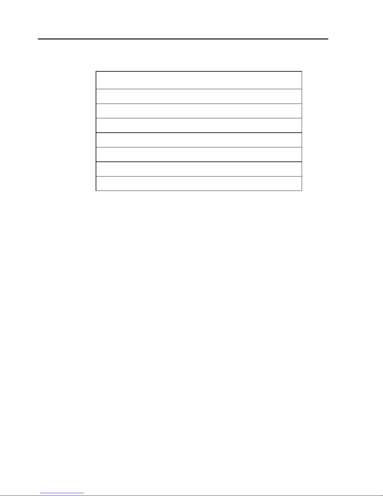
Use this table to find the section for your operating system.
For this operating
system… See this section…
®
operating
®
MDlib Application Program Interface (API) for
Windows 2000 or
Windows NT
Solaris 2.x Chapter 3, “DOME MDlib API
®
Chapter 2, “Dynamic Link Library” on
page 9
Function Reference” on page 67
Page 7
About This Guide vii
Conventions
This table explains the conventions used in the guide.
This
convention... Indicates...
Monospaced
type
Italic type
Bold type
File -> Open
<Key>
Computer code or directory; backslash (\)
indicates continuation of previous line of
UNIX code.
New or technical term; book title; or variable,
such as
Menu selection.
Select Open from the File menu.
Key name, such as
Information you should know regarding a
particular topic or procedure.
Information that can prevent potential
damage to hardware or software.
A helpful tip or an alternative method of
performing a procedure.
x.
<Enter>.
Page 8
viii PCI Products Developer’s Guide
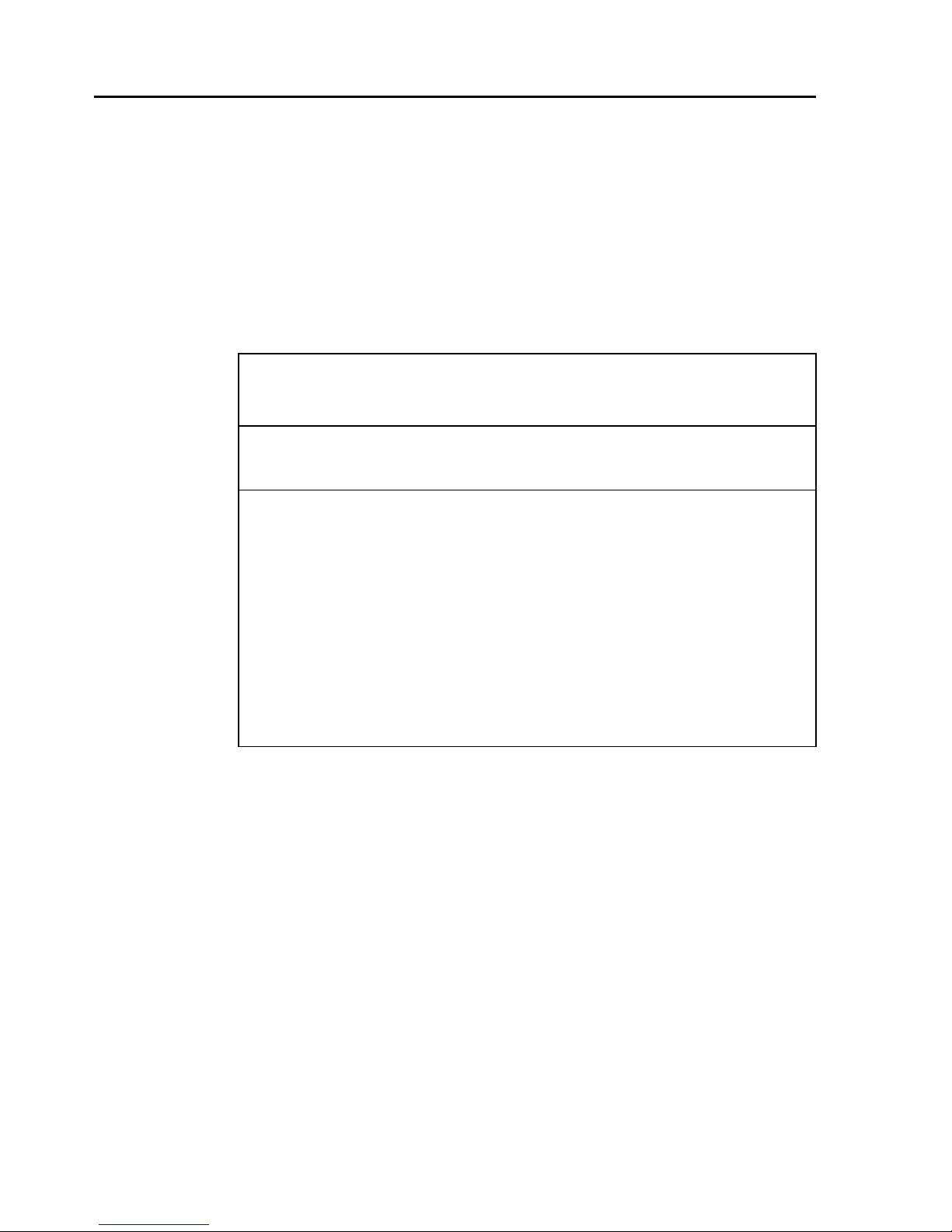
What’s in this guide
This table describes the organization of the guide.
This chapter… Provides…
Chapter 1
Board Architecture
Chapter 2
Dynamic Link Library
Chapter 3
DOME MDlib API
Function Reference
Architecture drawings for the
Md2/PCI, Md4/PCI, Md5/PCI, and
Md8/PCI boards, and an explanation
of gamma correction and 10-bit DACs.
Detailed descriptions of the data types
and functions of the DOME DLL for
Windows operating systems. It
explains the DOME data types and
gives detailed descriptions of each
DLL function. The functions are
organized logically. For example,
DSetGCT
Detailed descriptions of the types,
structures, and functions of the DOME
MDlib API. Use these functions with
Solaris operating systems only.
Functions are organized logically, in
the order in which they appear as
members of the
is followed by
DMdDev
DGetGCT
structure.
.
Related documentation
For more information about your board or related
DOME products, refer to these books:
• Md2/PCI Display Controller Installation Guide
• Md4/PCI Display Controller Installation Guide
• Md5/PCI Display Controller Installation Guide
• Md8/PCI Display Controller Installation Guide
• Calibration TQA User’s Guide
• DIMPL Library Reference
Page 9

Board Architecture 1
Chapter 1
Board Architecture
In This Chapter
• Md2/PCI Board Architecture 2
• Md4/PCI Board Architecture 3
• Md5/PCI Board Architecture 4
• Md8/PCI Board Architecture 5
• Gamma Correction and the 10-Bit DAC 6
Page 10
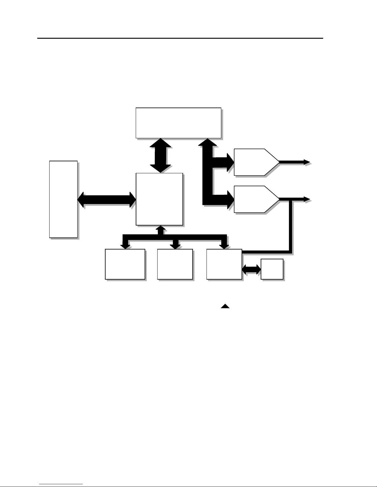
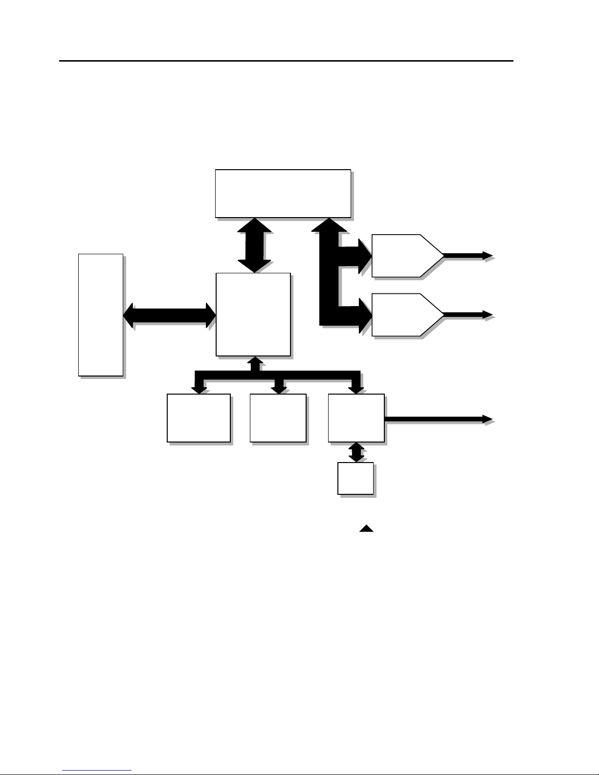
2 Chapter 1
Md2/PCI Board Architecture
This figure shows the Md2/PCI™ board architecture.
Video Memory
4 MB VRAM
PCI
Local
Bus
32
Luminance
Calibr at o
in
Port
Md2/PCI board architecture
128
GUI & Copy
Accelerator
(I-128)
Masking
DRAM
64
VGA
Contr oller
10-bit DAC
Video
Video
10-bit DAC
VGA
DRAM
Page 11
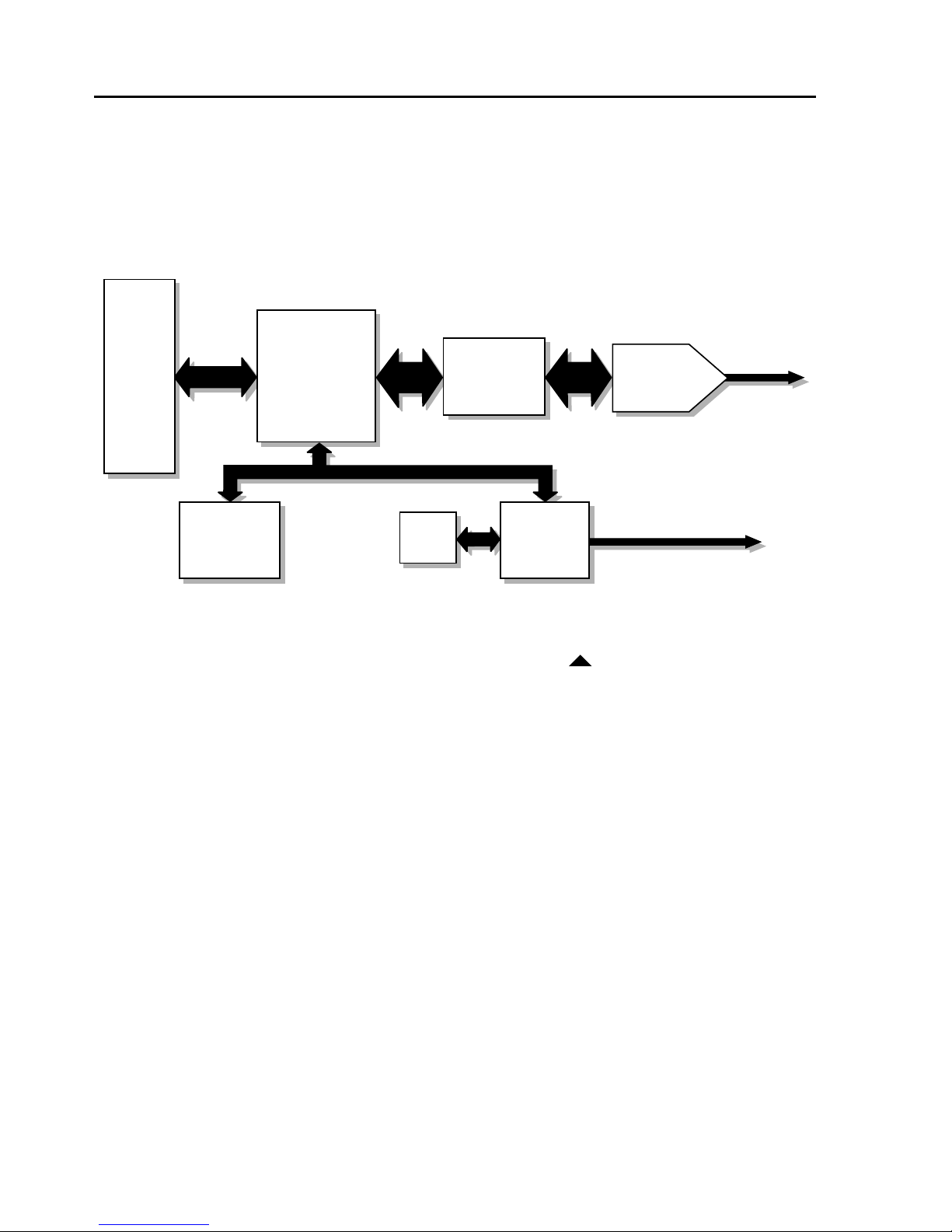
Board Architecture 3
Md4/PCI Board Architecture
This figure shows the Md4/PCI™ board architecture.
Video Memory
8 MB VRAM
128
128
128
10-bit DAC
Video
PCI
Local
Bus
GUI & Copy
32
Accelerator
(I-128)
Luminance
Calibr at o
in
Port*
* PS/2 or access bus supported
Md4/PCI board architecture
Masking
DRAM
10-bit DAC
VGA
Contr oller
VGA
DRAM
Video
Optional VGA Video
Page 12
4 Chapter 1
Md5/PCI Board Architecture
This figure shows the Md5/PCI™ board architecture.
PCI
Local
Bus
GUI & Copy
32
Accelerator
Luminance
Calibr at o
in
Port*
* PS/2 or access
bus supported
(I-128)
Md5/PCI board architecture
Video
128 128
Memory
8 MB VRAM
VGA
DRAM
VGA
Contr oller
10-bit DAC
Video
Optional VGA Video
Page 13

Board Architecture 5
Md8/PCI Board Architecture
This figure shows the Md8/PCI™ board architecture.
PCI
Local
Bus
GUI & Copy
32
Accelerator
Luminance
Calibration
Port*
* PS/2
(I-128)
Video
128 128
Memory
8 MB VRAM
32
VGA
DRAM
Md8/PCI board architecture
VGA
Controller
10-bit DAC
Video
Optional VGA Video
Page 14

6 Chapter 1
Gamma Correction and the 10-Bit DAC
The Md2/PCI, Md4/PCI, Md5/PCI, and Md8/PCI display
controllers (boards) use a 10-bit digital-to-analog converter
(DAC) in their video output circuitry. Nearly all competitive display boards use 8-bit DACs.
The DAC converts the digital image data stored in the
board’s video memory to an analog signal that drives the
monitor. An 8-bit DAC can send no more than 256 different
analog values to the monitor, while a 10-bit DAC can
provide up to 1024 values. An 8-bit DAC can therefore
result in as much as a 30% reduction in gray shades available to display an image. With such a reduction, critical
image details can be lost.
Display monitors do not produce a linear response across
the full range of pixel values. If there are 256 possible analog values, the change in luminance from value 0 (zero) to
value 1 (one) is different than the change from value 127 to
128. Likewise, doubling the pixel value sent to the monitor
does not precisely double the displayed brightness.
Gamma correction
This nonlinearity can be corrected using a method known
as
gamma correction
table compensates for the nonlinearity by adjusting the
values sent to the monitor.
An 8-bit DAC can produce only 256 such values, and
a nonlinear translation must sacrifice some of these values.
. With this technique, the DAC’s lookup
For this reason, gamma correction performed with an 8-bit
DAC sends substantially fewer than 256 distinct values to
the monitor.
Page 15

Board Architecture 7
The 10-bit DAC on the Md2/PCI, Md4/PCI, Md5/PCI, and
Md8/PCI boards can produce up to 1024 distinct analog
values. Thus, the boards can perform gamma correction
and send 256 distinct pixel values to the monitor, to produce a truer, more accurate grayscale image.
Accessing the gamma correction tables
You can access the
Windows
®
and Solaris™ operating systems.
gamma correction tables
(GCTs) in both
GCTs in Windows
If you are using a Windows operating system, apply the
Dynamic Link Library (DLL) provided with the DOME
®
Windows driver to set the GCT. For more information,
see “DSetGCT” on page 48.
The Windows operating system uses 8-bit color. Once
you set the GCT, the DOME Windows driver translates
all palette changes to the 10-bit value.
GCTs in Solaris
If you are using a Solaris operating system, initialize
the GCT to a linear ramp and load it into the hardware
with the
InitGCT
function (page 100) of the MDlib API.
Page 16

Page 17
Dynamic Link Library 9
Chapter 2
Dynamic Link Library
In This Chapter
• DLL Data Types 10
• Windows NT DLL 11
• Windows 2000 DLL 12
• Using Functions in Multi-Monitor and
Windows NT 4.0-Compatible Modes 15
• New Functions in the Windows 2000 DLL 18
• DLL Functions 19
Page 18
10 Chapter 2
DLL Data Types
The
mdpcint
of functions that links Windows operating systems and
DOME software applications. This section describes the
data types specific to DOME as well as the Windows
types and structures used in the DLL.
DOME types
The standard C types of
different things to different compilers. The DOME types,
however, are strictly defined as signed or unsigned and
by byte size, as shown in this table.
Size Signed Unsigned
1 byte
Dynamic Link Library (DLL) is a group
char, int
DOME Types
SBYTE UBYTE
, and
long
can mean
2 bytes
4 bytes
SWORD UWORD
SDWORD UDWORD
Windows types and structures
The DLL uses standard Windows types and structures, as
shown in this table.
Windows Types and Structures
Type or Structure Definition
DWORD
HDC
SIZE SIZE
POINT POINT
Unsigned 4 bytes
Handle to display-device context
structure as defined on page 33
structure as defined on page 35
Page 19

Dynamic Link Library 11
Windows NT DLL
All DOME Windows drivers include the
mdpcint.dll
library. This DLL provides an application interface to
the driver.
When working in Windows NT
®
4.0-compatible mode,
use only functions without the MM suffix.
Other functions listed in this chapter are not available
for the Windows NT operating system; these include
all functions with the MM suffix.
Page 20

12 Chapter 2
Windows 2000 DLL
All DOME Windows drivers include the
library. This DLL provides an application interface to
the driver.
The Windows
®
2000 DLL has some significant differences
from previous versions of the DLL. For example, the new
version of
mdpcint.dll
does not run on the Windows NT 4.0 operating system.
But, given a Windows NT 4.0-compatible screen configuration, programs written for Windows NT 4.0 will work
unchanged under Windows 2000 with the new DLL.
Windows 2000 DLL modes
Most functions in the Windows 2000 DLL have these
three modes:
• Full Windows NT 4.0-compatible mode
is
mdpcint.dll
not
backward-compatible. It
• Partial Windows NT 4.0-compatible mode
• Multi-monitor mode
The parameters to each function determine the mode.
Where possible, function names and parameters in the
Windows 2000 DLL use the same names and parameters
as they did in previous versions. The main difference
among the modes is in the way applications use the
parameters.
Page 21

Dynamic Link Library 13
Full Windows NT 4.0-compatible mode
A system that is fully compatible with the Windows NT
4.0 operating system meets these criteria:
• All screens are driven by the same type of DOME
board, all at the same resolution.
• All screens combine to make a rectangle with no gaps.
• All screens are in nonnegative space.
Partial Windows NT 4.0-compatible mode
Partial Windows NT 4.0-compatible mode includes
these features:
• One system can include both DOME and other brands
of boards.
• One system can run different DOME board types
simultaneously.
• Screens do not have to combine to make a rectangle.
• All DOME screens are in nonnegative space.
When running in partial Windows NT 4.0-compatible
mode, these
Get
routines return an error, unless all
DOME displays have the same value:
DGetBoardType
•
•
DGetDriverVersion
DGetNumGCTBits
•
•
DGetRefreshRate
DGetNumScreens
returns the number of DOME screens
only (in all modes).
Page 22
14 Chapter 2
Multi-monitor mode
Multi-monitor mode works with any Windows 2000
desktop. Multi-monitor mode includes these features:
• One system can include both DOME and other brands
of boards.
• One system can run different DOME board types
simultaneously.
• One board can support different palette types on
each monitor.
• Screens do not have to combine to make a rectangle.
• Screens can be unattached from the Windows
desktop.
Changing displays in the Windows 2000
virtual desktop
If you change any of the display properties in the
Windows 2000 virtual desktop (for example, if you
change resolution, placement, or detachment), you
must unload and then reload the DLL as follows:
• To unload the DLL, exit all programs that are using
the DLL, including the DOME tab.
• To reload the DLL, start any program that accesses
the DLL.
Page 23

Dynamic Link Library 15
Using Functions in Multi-Monitor and
Windows NT 4.0-Compatible Modes
Multi-monitor and the Windows NT 4.0-compatible
modes treat functions differently depending on the
function’s parameters. This section describes how
functions work in these modes.
Using functions that require HDC and
screen-number parameters
For functions that require both an HDC (handle to
display-device context) and screen number, the modes
differ as follows:
• In Windows NT 4.0-compatible modes (full and partial),
the
HDC
number is the
• Multi-monitor mode is signaled by combining the high
bit in the screen-number parameter with the Windows
2000 display number. The application can create the
hdc
parameter to the functions. If the application wants
the DLL to create the
parameter. Otherwise, the DLL creates a DC using
the display number. For an example of each method,
see “DGetDriverVersionMM” on page 23.
• Always use the
is from any screen display, and the screen
Windows NT 4.0 virtual screen number.
for the particular display and supply it as the first
hdc
hdc
, it uses
for unattached displays.
NULL
as the first
The Windows NT 4.0 virtual screen number is the screen
number assigned by the DLL and is independent of the
operating system. The DLL counts only DOME screens.
Page 24
16 Chapter 2
The Windows 2000 display number is the same as that
passed to the GDI (graphical device interface) function
EnumDisplayDevices
(the number shown via Identify
minus one).
The GDI call uses 32-bit numbers, while the DOME DLL
uses 16-bit numbers.
Example
WIN2K_DISPLAY_NUMBER
is defined in mdpcint.h as
0x8000. This code sample shows how to cast the display
number in the DLL:
nDisplay = (UWORD) Win2000DisplayNum |
WIN2K_DISPLAY_NUMBER;
Using functions that do not include HDC and
screen-number parameters
Functions that previously did not include a screennumber parameter are obsolete in multi-monitor mode.
Those that still provide useful information have been
rewritten with the MM suffix and
hdc and display-
number parameters.
Example For example, Windows NT 4.0-compatible applications
use the
DGetBoardType (HDC hdc, UWORD FAR * lpRetType)
DGetBoardType function like this:
Multi-monitor applications use DGetBoardType
like this:
DGetBoardTypeMM (HDC hdc, UWORD nDisplay,
UWORD FAR * lpRetType)
DGetMaxScreens and DGetNumBoards are obsolete in
both modes.
Page 25

Dynamic Link Library 17
DDirectBlt
is only available in Windows NT 4.0compatible mode. Currently this function is not fully
operational: although it splits the
blt between screens
correctly, GDI does not send the driver the correct clip,
and the driver overdraws overlapping windows.
Page 26
18 Chapter 2
New Functions in the Windows 2000 DLL
These functions exist only in multi-monitor mode and
are new in the Windows 2000 DLL:
DGetPaletteTypeMM
•
• DGetSisterDisplayRegPathMM
• DGetSisterDisplayNumberMM
A sister display is one of two displays being driven by
the same DOME board.
This table lists each updated function and the obsolete
function it replaces.
Multi-Monitor Functions
That Replace Obsolete Functions
This new function… Replaces this function…
DGetBoardTypeMM DGetBoardType
DGetDriverVersionMM DGetDriverVersion
DGetNumGCTBitsMM DGetNumGCTBits
DGetNumGDIBitsMM DGetNumGDIBits
DGetRefreshRateMM DGetRefreshRate
All functions with the MM suffix are available only in
Windows 2000 and work only in multi-monitor mode.
The previous versions (without the MM suffix) work in
Windows NT 4.0-compatible mode.
Page 27
Dynamic Link Library 19
DLL Functions
Use the DLL functions described in this section to write
applications. The functions are listed logically; for example,
DSetGCT
For a description of this function… See page…
DGetDriverVersion 21
DGetDriverVersionMM 23
DGetLibraryVersion 25
DGetBoardType 26
DGetBoardTypeMM 28
DGetNumBoards 30
DGetNumScreens 31
DGetMaxScreens 32
DGetScreenDimensions 33
is followed by DGetGCT.
Description of DLL Functions
DGetScreenPlacement 35
DGetNumGCTBits 37
DGetNumGCTBitsMM 38
DGetNumGDIBits 39
DGetNumGDIBitsMM 40
DGetSisterDisplayRegPathMM 42
DGetSisterDisplayNumberMM 44
DDirectBlt 45
DGetPaletteTypeMM 47
DSetGCT 48
DGetGCT 50
DSetStartupGCT 52
Page 28
20 Chapter 2
Description of DLL Functions (Cont.)
For a description of this function… See page…
DCancelStartupGCT 54
DGetRefreshRate 55
DGetRefreshRateMM 56
DCalibratorInit 57
DCalibratorMeasure 60
DGetFtLamScale 62
DSerialCmd 64
Page 29
DGetDriverVersion 21
DGetDriverVersion
Purpose Use DGetDriverVersion to return the version number of
the DOME Windows driver.
Syntax
DWORD DGetDriverVersion (hdc, lpwDriverVersion)
DGetDriverVersion Parameters
Parameter
Type Name Description
HDC hdc Handle to the display-
device context.
UWORD FAR * wDriverVersion Pointer to UWORD.
It is filled in with a
hexadecimal value. The
high byte is the version
number , and the low b yte
is the revision number.
For example, 0x108 is
returned when you’re
using the version 1.8
driver.
Return value DWORD – zero (0) if function completed successfully;
otherwise, operating system error code.
Page 30

22 DGetDriverVersion
Example This example returns the driver version in
wDriverVersion.
#include <mdpcint.h>
{
HDC hdc;
UWORD wDriverVersion;
DWORD dwRetCode;
dwRetCode + DGetDriverVersion (hdc,
&wDriverVersion);
return dwRetCode;
}
See also DGetLibraryVersion
Page 31

DGetDriverVersionMM 23
DGetDriverVersionMM
(Windows 2000, multi-monitor mode only)
Purpose Use
DOME Windows driver for your board.
Syntax
DWORD DGetDriverVersionMM (hdc, nDisplay,
Parameter
Type Name Description
HDC hdc Handle to the display-
UWORD nDisplay Target display.
UWORD FAR * lpDriverVersion Pointer to UWORD.
DGetDriverVersionMM to return the version of the
lpDriverVersion)
DGetDriverVersionMM Parameters
device context.
It is filled in with a
hexadecimal value. The
high byte is the version
number, and the low byte
is the revision number.
For example, 0x500 is
returned when you’re
using the version 5.0.0
driver.
Return value DWORD – zero (0) if function completed successfully;
otherwise, operating system error code.
Page 32

24 DGetDriverVersionMM
Example This example returns the driver version in
lpDriverVersion
#include <mdpcint.h>
{
HDC hdc;
UWORD nDisplay = (UWORD) Win2000DisplayNum |
WIN2K_DISPLAY_NUMBER;
DWORD dwRetCode;
UWORD DriverVersion;
dwRetCode = DGetDriverVersionMM
(NULL, nDisplay, &DriverVersion);
return dwRetCode;
}
.
Or, for attached or unattached display 2:
DEVMODE dmMode; HDC hdc;
/* Fill in relevant parts of dmMode. */
hdc = CreateDC ("DISPLAY", "\\\\.\\DISPLAY2",
NULL, &dmMode);
dwRetCode = DGetDriverVersionMM (hdc,
WIN2K_DISPLAY_NUMBER, &DriverVersion);
See also DGetLibraryVersion and GetFileVersionInfo
function of the Microsoft SDK
Page 33

DGetLibraryVersion 25
DGetLibraryVersion
Purpose Use DGetLibraryVersion to return the version of the
DOME Windows DLL.
Syntax
DWORD DGetLibraryVersion (lpwLibraryVersion)
DGetLibraryVersion Parameters
Parameter
Type Name Description
UWORD FAR * wLibraryVersion Pointer to UWORD.
It is filled in with a
hexadecimal value.
The high byte is the
version number, and
the low byte is the
revision number. For
example, 0x201 is
returned when you’re
using the version 2.1
library.
Return value DWORD – zero (0) if function completed successfully;
otherwise, operating system error code.
Example This example returns the library version in
wLibraryVersion
#include <mdpcint.h>
{
UWORD wLibraryVersion;
DWORD dwRetCode;
dwRetCode = DGetLibraryVersion
(&wLibraryVersion);
return dwRetCode;
}
See also DGetDriverVersion and GetFileVersionInfo function
of the Microsoft SDK
.
Page 34

26 DGetBoardType
DGetBoardType
(Obsolete in multi-monitor mode)
Purpose Use
(Md2/PCI, Md4/PCI, Md5/PCI, or Md8/PCI).
Syntax
DWORD DGetBoardType (hdc, lpwBoardType)
Parameter
Type Name Description
HDC hdc Handle to the display-
UWORD FAR * wBoardType Pointer to UWORD; on
DGetBoardType to return the board type
DGetBoardType Parameters
device context.
successful return, it
contains one of these
values:
•MD2PCI
•MD4PCI
•MD5PCI
•MD8PCI
Return value DWORD – zero (0) if function completed successfully;
otherwise, operating system error code
This function is valid with version 1.08 and later of
the DLL.
Page 35

DGetBoardType 27
Example This example returns the board type.
#include <mdpcint.h> /* has board definitions */
{
HDC hdc;
UWORD wBoardType;
DWORD dwRetCode;
dwRetCode = DGetBoardType (hdc, &wBoardType);
return dwRetCode;
}
See also DGetNumBoards
Page 36

28 DGetBoardTypeMM
DGetBoardTypeMM
(Windows 2000, multi-monitor mode only)
Purpose Use
(Md2/PCI, Md4/PCI, Md5/PCI, or Md8/PCI).
Syntax
DWORD DGetBoardTypeMM (hdc, nDisplay,
Parameter
Type Name Description
HDC hdc NULL or hdc of target display.
UWORD nDisplay Target display.
UWORD FAR * retType Pointer to UWORD; on successful
DGetBoardTypeMM to return the board type
lpwretType)
DGetBoardTypeMM Parameters
return, it contains one of these
values:
•MD2PCI
•MD4PCI
•MD5PCI
•MD8PCI
Return value DWORD – zero (0) if function completed successfully;
otherwise, operating system error code.
Page 37

DGetBoardTypeMM 29
Example This example returns the board type.
#include <mdpcint.h>
{
HDC hdc;
UWORD nDisplay = (UWORD) Win2000DisplayNum |
WIN2K_DISPLAY_NUMBER;
DWORD dwRetCode;
UWORD retType;
dwRetCode = DGetBoardTypeMM (NULL, nDisplay,
&retType);
return dwRetCode;
}
See also DGetNumBoards
Page 38

30 DGetNumBoards
DGetNumBoards
(Obsolete in Windows 2000)
Purpose Use
PCI boards in your system.
Syntax
DWORD DGetNumBoards (hdc, lpwNumBoards)
Parameter
Type Name Description
HDC hdc Handle to the display-device
UWORD FAR * wNumBoards Pointer to UWORD. It is always
DGetNumBoards to return the number of DOME
DGetNumBoards Parameters
context.
filled in with 1 (one) for Windows
2000 and with the actual
number of DOME boards for
Windows NT 4.0 on successful
return.
Return value DWORD – zero (0) if function completed successfully;
otherwise, operating system error code.
See also
DGetBoardType
Page 39

DGetNumScreens 31
DGetNumScreens
Purpose Use DGetNumScreens to return the number of screens
controlled by the DOME Windows driver.
Syntax
DWORD DGetNumScreens (hdc, lpwNumScreens)
DGetNumScreens Parameters
Parameter
Type Name Description
HDC hdc Handle to the display-device
context.
UWORD FAR * wNumScreens Pointer to UWORD. It is filled
in with the number of screens
controlled by the DOME
Windows driver.
Return value DWORD – zero (0) if function completed successfully;
otherwise, operating system error code.
Example This example returns the number of screens controlled by
DOME Windows drivers.
#include <mdpcint.h>
{
HDC hdc;
UWORD wNumScreens;
DWORD dwRetCode;
dwRetCode = DGetNumScreens (hdc, &wNumScreens);
return dwRetCode;
}
See also DGetScreenDimensions, DGetScreenPlacement,
DGetRefreshRate, DGetRefreshRateMM
Page 40

32 DGetMaxScreens
DGetMaxScreens
(Obsolete in Windows 2000)
Purpose Use
of Md2/PCI, Md4/PCI, Md5/PCI, or Md8/PCI screens
controlled by the DOME Windows driver.
Syntax
DWORD DGetMaxScreens (hdc, lpwNumScreens)
Parameter
Type Name Description
HDC hdc Handle to the display-device
UWORD FAR * wNumScreens Pointer to UWORD. It is filled in
DGetMaxScreens to return the maximum number
DGetMaxScreens Parameters
context.
with the maximum number of
screens controlled by the
DOME Windows driver. In
Windows NT, it is equivalent
to DGetNumScreens in
Windows 2000.
Return value DWORD – zero (0) if function completed successfully;
otherwise, operating system error code.
Example This example returns the maximum number of screens
controlled by the DOME Windows driver.
#include <mdpcint.h>
{
HDC hdc;
UWORD wNumScreens;
DWORD dwRetCode;
dwRetCode = DGetMaxScreens (hdc, &wNumScreens);
return dwRetCode;
See also DGetNumScreens
Page 41

DGetScreenDimensions 33
DGetScreenDimensions
Purpose Use DGetScreenDimensions to return the dimensions
of a single screen.
Syntax
DWORD DGetScreenDimensions (hdc, wScreenNumber,
lpszSize)
DGetScreenDimensions Parameters
Parameter
Type Name Description
HDC hdc Handle to the display-
device context.
UWORD wScreenNumber Target screen number
(zero-based).
SIZE FAR * szSize Pointer to a Microsoft
Windows SIZE structure.
It is filled in with the width
(cx) and height (cy) of
a single screen.
Return value DWORD – zero (0) if function completed successfully;
otherwise, operating system error code.
Structure This code fragment defines the
typedef struct
{
LONG cx;
LONG cy;
} SIZE;
SIZE structure.
Page 42

34 DGetScreenDimensions
Example This example returns the dimensions of screen zero (0).
#include <windows.h> /* includes SIZE
definition */
#include <mdpcint.h>
{
HDC hdc;
SIZE szSize;
DWORD dwRetCode;
dwRetCode = DGetScreenDimensions (hdc, 0,
&szSize);
return dwRetCode;
}
Or, in Windows 2000 mode:
dwRetCode = DGetScreenDimensions (NULL,
WIN2K_DISPLAY_NUMBER | 0, &szSize);
Or, in Windows 2000 mode with an unattached display:
dwRetCode = DGetScreenDimensions (hdc,
WIN2K_DISPLAY_NUMBER, &szSize);
See also DGetNumScreens, DGetScreenPlacement,
DGetRefreshRate, DGetRefreshRateMM
Page 43

DGetScreenPlacement 35
DGetScreenPlacement
Purpose Use DGetScreenPlacement to return the x,y position of
the screen in Windows space.
Syntax
DWORD DGetScreenPlacement (hdc, wScreenNumber,
lpptPoint)
DGetScreenPlacement Parameters
Parameter
Type Name Description
HDC hdc Handle to the display-
device context.
UWORD wScreenNumber Target screen number
(zero-based).
POINT FAR * ptPoint Pointer to a Windows
POINT structure. It is filled
in with the placement of
the screen.
Return value DWORD – zero (0) if function completed successfully;
otherwise, operating system error code.
This function returns an error for unattached displays.
Structure This code fragment defines the
typedef struct
{
LONG x;
LONG y;
} POINT;
POINT structure.
Page 44

36 DGetScreenPlacement
Example This example returns the x,y position of screen one (1) in
the Windows desktop.
#include <windows.h> /* includes POINT
definition */
#include <mdpcint.h>
{
HDC hdc;
POINT ptPosition;
DWORD dwRetCode;
dwRetCode = DGetScreenPlacement (hdc, 1,
&ptPosition);
return dwRetCode;
}
See also DGetNumScreens, DGetScreenDimensions,
DGetRefreshRate, DGetRefreshRateMM
Page 45

DGetNumGCTBits 37
DGetNumGCTBits
Purpose Use DGetNumGCTBits to return the number of gamma
correction bits.
Syntax
DWORD DGetNumGCTBits (hdc, lpNumRedBits,
lpNumGreenBits, lpNumBlueBits)
DGetNumGCTBits Parameters
Parameter
Type Name Description
HDC hdc Handle to the display-device
context
DWORD FAR * lpNumRedBits Number of red GCT bits
lpNumGreenBits Number of green GCT bits
lpNumBlueBits Number of blue GCT bits
Return value DWORD – zero (0) if function completed successfully;
otherwise, operating system error code.
Example This example returns the number of gamma
correction bits.
#include <mdpcint.h>
{
HDC hdc
DWORD dwRetCode;
DWORD NumRedBits, NumGreenBits, NumBlueBits;
dwRetCode = DGetNumGCTBits (hdc, &NumRedBits,
&NumGreenBits, &NumBlueBits);
return dwRetCode;
}
See also DGetScreenDimensions, DGetNumGDIBits
Page 46

38 DGetNumGCTBitsMM
DGetNumGCTBitsMM
(Windows 2000, multi-monitor mode only)
Purpose Use
correction bits.
Syntax
DWORD DGetNumGCTBitsMM (hdc, nDisplay,
Parameter
Type Name Description
HDC hdc Handle to the display-device
UWORD nDisplay Target display
DWORD FAR * lpNumRedBits Number of red GCT bits
DGetNumGCTBitsMM to return the number of gamma
lpNumRedBits, lpNumGreenBits, lpNumBlueBits)
DGetNumGCTBitsMM Parameters
context
lpNumGreenBits Number of green GCT bits
lpNumBlueBits Number of blue GCT bits
Return value DWORD – zero (0) if function completed successfully;
otherwise, operating system error code.
Example This example returns the number of gamma correction bits.
#include <mdpcint.h>
{
HDC hdc;
UWORD nDisplay;
DWORD dwRetCode;
DWORD NumRedBits, NumGreenBits, NumBlueBits;
dwRetCode = DGetNumGCTBitsMM (NULL, nDisplay,
&NumRedBits, &NumGreenBits, &NumBlueBits);
return dwRetCode;
}
See also DGetScreenDimensions, DGetNumGDIBitsMM
Page 47

DGetNumGDIBits 39
DGetNumGDIBits
Purpose Use DGetNumGDIBits to return the number of Windows
GDI bits.
Syntax
DWORD DGetNumGDIBits (hdc, lpNumRedBits,
lpNumGreenBits, lpNumBlueBits)
DGetNumGDIBits Parameters
Parameter
Type Name Description
HDC hdc Handle to the display-device
context
DWORD FAR * lpNumRedBits Number of red bits used
by GDI.
lpNumGreenBits Number of green bits used
by GDI
lpNumBlueBits Number of blue bits used
by GDI.
Return value DWORD – zero (0) if function completed successfully;
otherwise, operating system error code.
Example This example returns the number of GDI bits.
#include <mdpcint.h>
{
HDC hdc;
DWORD dwRetCode;
DWORD NumRedBits, NumGreenBits, NumBlueBits;
dwRetCode = DGetNumGDIBits (hdc, &NumRedBits,
&NumGreenBits, &NumBlueBits);
return dwRetCode;
}
See also DGetScreenDimensions, DGetNumGCTBits
Page 48

40 DGetNumGDIBitsMM
DGetNumGDIBitsMM
(Windows 2000, multi-monitor mode only)
Purpose Use
Windows GDI bits.
Syntax
DWORD DGetNumGDIBitsMM (hdc, nDisplay,
Parameter
Type Name Description
HDC hdc Handle to the display-device
UWORD nDisplay Target display
DWORD FAR * lpNumRedBits Number of red bits used
DGetNumGDIBitsMM to return the number of
lpNumRedBits, lpNumGreenBits, lpNumBlueBits)
DGetNumGDIBitsMM Parameters
context
by GDI.
lpNumGreenBits Number of green bits used
by GDI
lpNumBlueBits Number of blue bits used
by GDI.
Return value DWORD – zero (0) if function completed successfully;
otherwise, operating system error code.
Page 49

DGetNumGDIBitsMM 41
Example This example returns the number of GDI bits.
#include <mdpcint.h>
{
HDC hdc;
UWORD nDisplay;
DWORD dwRetCode;
DWORD NumRedBits, NumGreenBits, NumBlueBits;
dwRetCode = DGetNumGDIBitsMM (NULL, nDisplay,
&NumRedBits, &NumGreenBits, &NumBlueBits);
return dwRetCode;
}
See also DGetScreenDimensions, DGetNumGCTBitsMM
Page 50

42 DGetSisterDisplayRegPathMM
DGetSisterDisplayRegPathMM
(Windows 2000, multi-monitor mode only)
Purpose Use
path of the Windows 2000 sister display.
Syntax
DWORD FAR PASCAL DGetSisterDisplayRegPathMM
(hdc, nDisplay, *lpRegPath, szRegPath)
Parameter
Type Name Description
HDC hdc Handle to the display-device context
UWORD nDisplay Target display
char FAR *lpRegPath On successful return, contains the
int szRegPath Size of supplied buffer; must be
DGetSisterDisplayRegPathMM to return the registry
DGetSisterDisplayRegPathMM Parameters
registry path of the sister display to
wDisplay
at least 256 bytes
Return value Zero (0) if successful; otherwise, an error message.
Page 51

DGetSisterDisplayRegPathMM 43
Example This example returns the registry path of the sister display
to the target display.
#include <mdpcint.h>
{
HDC hdc;
UWORD nDisplay = (UWORD) Win2000DisplayNum |
WIN2K_DISPLAY_NUMBER;
DWORD dwRetCode;
char lpRegPath[256];
dwRetCode = DGetSisterDisplayRegPathMM
(NULL, nDisplay, lpRegPath, 256);
return dwRetCode;
}
See also DGetSisterDisplayNumberMM
Page 52

44 DGetSisterDisplayNumberMM
DGetSisterDisplayNumberMM
(Windows 2000, multi-monitor mode only)
Purpose Use
Windows 2000 display number of the sister display.
Syntax
DWORD FAR PASCAL DGetSisterDisplayNumberMM
(hdc, nDisplay, lpDisplayNum)
Parameter
Type Name Description
HDC hdc Handle to the display-device
UWORD nDisplay Target display
UWORD FAR *DisplayNum On successful return,
DGetSisterDisplayNumberMM to return the
DGetSisterDisplayNumberMM Parameters
context
contains the Windows 2000
display number of the sister
display
Return value Zero (0) if successful; otherwise, an error message.
Example This example returns the Windows 2000 display number
of the sister display.
#include <mdpcint.h>
{
HDC hdc;
UWORD nDisplay = (UWORD) Win2000DisplayNum |
WIN2K_DISPLAY_NUMBER;
DWORD dwRetCode;
UWORD nSisterDisplay;
dwRetCode = DGetSisterDisplayNumberMM
(NULL, nDisplay, &nSisterDisplay);
return dwRetCode;
}
See also DGetSisterDisplayRegPathMM
Page 53

DDirectBlt 45
DDirectBlt
(Obsolete in multi-monitor mode)
Purpose Use
data from the host to the screen(s).
Syntax
DWORD DDirectBlt (hdc, DestX, DestY, SrcX, SrcY,
Parameter
Type Name Description
HDC hdc Handle to the display-device
int DestX, DestY Destination screen coordinates.
int SrcX, SrcY Pixel offsets into the source
DDirectBlt to provide a direct transfer of image
Width, Height, SrcStride, lpSrc)
DDirectBlt Parameters
context.
The top-left corner of the top-left
screen is 0,0. This function splits
the transfer among screens,
if necessary.
buffer where the transfer starts.
int Width Number of pixel columns to
int Height Number of pixel rows to transfer.
int SrcStride Number of bytes from the
void * lpSrc Pointer to the source buffer.
transfer.
beginning of one source line
to the beginning of the next
source line.
The source buffer image must
have the same bits per pixel
as the screen.
Page 54

46 DDirectBlt
When you use DDirectBlt, make sure that the values of
SrcX + Width
and SrcY + Height do not exceed the
bounds of the source image. Otherwise, you risk a system
memory access error.
Return value DWORD – zero (0) if function completed successfully;
otherwise, operating system error code.
Example This example transfers image data from the host to
the screen.
#include <mdpcint.h>
{
HDC hdc;
int DestX, DestY, SrcX, SrcY, Width, Height,
SrcStride;
void *lpSrc
DWORD dwRetCode;
.
.
.
dwRetCode = DDirectBlt (hdc, DestX, DestY, SrcX,
SrcY, Width, Height, SrcStride, lpSrc);
return dwRetCode;
}
Page 55

DGetPaletteTypeMM 47
DGetPaletteTypeMM
(Windows 2000, multi-monitor mode only)
Purpose Use
the Windows 2000 display.
Syntax
DGetPaletteTypeMM (hdc, nDisplay, lppalType)
Parameter
Type Name Description
HDC hdc Handle to the display-device context
UWORD nDisplay Target display
UWORD FAR *palType Palette type of display; on successful
DGetPaletteTypeMM to return the palette type of
DGetPaletteTypeMM Parameters
return, it contains one of these values:
•PALTYPE_PSEUDOCOLOR
•PALTYPE_DYNAMIC_GRAY
•PALTYPE_STATIC_GRAY
•PALTYPE_NONLINEAR_STATIC_GRAY
•PALTYPE_TRUECOLOR
Return value Zero (0) if successful; otherwise, an error message.
Example This example returns the palette type of the display.
#include <mdpcint.h> /* has PALTYPE
definitions */
{
HDC hdc;
UWORD nDisplay = (UWORD) Win2000DisplayNum |
WIN2K_DISPLAY_NUMBER;
DWORD dwRetCode;
UWORD palType;
dwRetCode = DGetPaletteTypeMM (NULL, nDisplay,
&palType);
return dwRetCode;
}
Page 56

48 DSetGCT
DSetGCT
Purpose Use DSetGCT to set the GCT for a particular screen.
Syntax
DWORD DSetGCT (hdc, wScreenNumber, lpgct)
DSetGCT Parameters
Parameter
Type Name Description
HDC hdc Handle to the display-
device context.
UWORD wScreenNumber Target screen number
(zero-based).
GAMMA_
CORRECTION_
TABLE FAR *
gct Pointer to GCT.
ArraySize specifies
the number of entries in
each color array. For
current versions of the
DLL, ArraySize must
be 256. The table’s color
values are 16-bit values.
The DLL shifts these
values down if the DAC
doesn’t support the full
16 bits.
Return value DWORD – zero (0) if function completed successfully;
otherwise, operating system error code.
Grayscale boards use green values only.
Page 57

DSetGCT 49
Structure This code fragment defines the only valid structure for the
GAMMA_CORRECTION_TABLE in this version of the library.
typedef struct
{
UWORD Reserved1;
UWORD Reserved2;
UWORD ArraySize;
UWORD Red[256];
UWORD Green[256];
UWORD Blue[256];
} GAMMA_CORRECTION_TABLE;
DSetGCT
overwrites the Reserved1 and Reserved2
fields in the GAMMA_CORRECTION_ TABLE. The ArraySize
field must be 256.
Example This example sets the GCT for screen zero (0).
#include <mdpcint.h> /* includes GAMMA_
CORRECTION_TABLE
definition */
{
HDC hdc;
GAMMA_CORRECTION_TABLE gct;
DWORD dwRetCode;
gct.ArraySize = 256;
/* Set Red, Green, and Blue values of gct. */
.
.
.
dwRetCode = DSetGCT (hdc, 0, &gct);
return dwRetCode;
}
See also DGetGCT, DSetStartupGCT, DCancelStartupGCT
Page 58

50 DGetGCT
DGetGCT
Purpose Use DGetGCT to return the GCT for a particular screen.
Syntax
DWORD DGetGCT (hdc, wScreenNumber, lpgct)
DGetGCT Parameters
Parameter
Type Name Description
HDC hdc Handle to the display-
device context.
UWORD wScreenNumber Target screen number
(zero-based).
GAMMA_
CORRECTION_
TABLE FAR *
gct Pointer to GCT. Color
values in the table are full
16-bit values.
Return value DWORD – zero (0) if function completed successfully;
otherwise, operating system error code.
Structure The code fragment on page 49 defines the
GAMMA_CORRECTION_TABLE
DGetGCT overwrites the Reserved1 and Reserved2
structure.
fields in the GAMMA_CORRECTION_ TABLE. The ArraySize
field must be 256.
Page 59

DGetGCT 51
Example This example returns the GCT for screen zero (0).
#include <mdpcint.h> /* includes GAMMA_
CORRECTION_TABLE
definition */
{
HDC hdc;
GAMMA_CORRECTION_TABLE gct;
DWORD dwRetCode;
dwRetCode = DGetGCT (hdc, 0, &gct);
return dwRetCode;
}
See also DSetGCT, DSetStartupGCT, DCancelStartupGCT
Page 60

52 DSetStartupGCT
DSetStartupGCT
Purpose Use DSetStartupGCT to set the initial GCT for a particular
screen. This table loads whenever you start the Windows
operating system. The GCT supplied to this function takes
Syntax
effect only when you restart Windows.
DSetStartupGCT
can also replace a previous startup table.
DWORD DSetStartupGCT (wScreenNumber, lpFileName)
DSetStartupGCT Parameters
Parameter
Type Name Description
UWORD wScreenNumber Target screen number
(zero-based).
SBYTE FAR * FileName Full path of the file
containing the GCT. The
colors in the file are full
16-bit values. IdGCT
must equal 0xD03E9A3A.
You must set Version
to 1 (one) for current
versions of the DLL.
Return value DWORD – zero (0) if function completed successfully;
otherwise, operating system error code.
DSetStartupGCT
Delete the original GCT file to preserve disk space.
copies the GCT file to a system directory.
Page 61

DSetStartupGCT 53
Structure This code fragment defines the GCT_FILE_FORMAT
structure.
typedef struct
{
UDWORD IdGCT;
UWORD Version;
UWORD ArraySize;
UWORD Red[256];
UWORD Green[256];
UWORD Blue[256];
} GCT_FILE_FORMAT;
The ArraySize field must be 256.
Example This example sets the initial GCT for screen zero (0).
#include <mdpcint.h>
{
DWORD dwRetCode;
dwRetCode = DSetStartupGCT (0, "screen0.gct");
return dwRetCode;
}
See also DCancelStartupGCT, DGetGCT, DSetGCT
Page 62

54 DCancelStartupGCT
DCancelStartupGCT
Purpose Use DCancelStartupGCT to cancel the startup GCT for a
particular screen. When you start the Windows operating
system after setting this function, the default (linear) GCT
loads for the indicated screen. This function takes effect
only when you restart the Windows operating system.
Syntax
DWORD DCancelStartupGCT (wScreenNumber)
DCancelStartupGCT Parameters
Parameter
Type Name Description
UWORD wScreenNumber Target screen number
(zero-based)
Return value DWORD – zero (0) if function completed successfully;
otherwise, operating system error code.
Example This example cancels the initial GCT for screen zero (0).
#include <mdpcint.h>
{
DWORD dwRetCode;
dwRetCode = DCancelStartupGCT (0);
return dwRetCode;
}
See also DSetStartupGCT
Page 63

DGetRefreshRate 55
DGetRefreshRate
(Obsolete in multi-monitor mode)
Purpose Use
Syntax
DGetRefreshRate to return the screen’s refresh rate.
DWORD DGetRefreshRate (hdc, lpwRefreshRate)
DGetRefreshRate Parameters
Parameter
Type Name Description
HDC hdc Handle to the display-device
context.
UWORD FAR * wRefreshRate Pointer to UWORD. It is filled
in with the refresh rate in
Hertz * 100.
Return value DWORD – zero (0) if function completed successfully;
otherwise, operating system error code.
Example This example returns the refresh rate of the screen.
#include <mdpcint.h>
{
HDC hdc;
UWORD wRefreshRate;
DWORD dwRetCode;
dwRetCode = DGetRefreshRate (hdc,
&wRefreshRate);
return dwRetCode;
}
See also DGetNumScreens, DGetScreenDimensions,
DGetScreenPlacement
Page 64

56 DGetRefreshRateMM
DGetRefreshRateMM
(Windows 2000, multi-monitor mode only)
Purpose Use
refresh rate.
Syntax
DWORD DGetRefreshRateMM (hdc, nDisplay,
Parameter
Type Name Description
HDC hdc Handle to the display-
UWORD nDisplay Target display.
UWORD FAR * lpRefreshRate P ointer to UWORD FAR. It is
DGetRefreshRateMM to return the screen’s
lpRefreshRate)
DGetRefreshRateMM Parameters
device context.
filled in with the refresh rate
in Hertz * 100.
Return value DWORD – zero (0) if function completed successfully;
otherwise, operating system error code.
Example This example returns the refresh rate of the screen.
#include <mdpcint.h>
{
HDC hdc
UWORD nDisplay = (UWORD) Win2000DisplayNum |
WIN2K_DISPLAY_NUMBER;
DWORD dwRetCode;
UWORD RefreshRate;
dwRetCode = DGetRefreshRateMM (NULL, nDisplay,
&lpRefreshRate);
return dwRetCode;
}
See also DGetScreenDimensions, DGetScreenPlacement
Page 65

DCalibratorInit 57
DCalibratorInit
Purpose Use DCalibratorInit to initialize the DOME
Calibration TQA™ and prepare it for taking
measurements.
Syntax
DWORD DCalibratorInit (hdc, wScreenNumber,
lpInitStruct)
DCalibratorInit Parameters
Parameter
Type Name Description
HDC hdc Handle to the display-
device context
UWORD wScreenNumber Target screen number
(zero-based)
INIT_
CALIBRATOR_
STRUCT FAR *
InitStruct Pointer to INIT_
CALIBRATOR_ STRUCT
structure
Return value DWORD – zero (0) if function completed successfully;
otherwise, operating system error code.
Structure This code fragment defines the
structure.
typedef struct
{
UWORD Version;
UWORD MeasurementTime;
DWORD ReadTimeout;
UDWORD Reserved;
} INIT_CALIBRATOR_STRUCT;
You must set Version to 2.
INIT_CALIBRATOR_STRUCT
Page 66

58 DCalibratorInit
MeasurementTime
which the sample is taken in
is the number of microseconds over
DCalibratorMeasure
(page 60). This parameter must be greater than 17 and
less than 1,179,630.
When measuring a periodic source such as a monitor,
sample at an integer number of periods. Setting the proper
integration time for a monitor at a specific frequency is
essential to obtaining accurate, repeatable measurements.
Each value set in
MeasurementTime is equal to one (1)
microsecond. Use this equation to find the integration time:
period of
one cycle
-------------------- =
00010600
integration time for one cycle
Multiply the integration time by the number of cycles
you want to measure (31 cycles are recommended). For
example, with a 75 Hz monitor, use this calculation:
1
----- 75
6
10
× 31× 413333=
Thus, the integration time is:
413,333 microseconds = .413 seconds
ReadTimeout is the number of milliseconds to wait for
data when reading from the calibrator port.
You can still use Version 1 (one) of the structure, which
does not include
(one), the
ReadTimeout value defaults to 2000 (2 seconds),
and you must set
ReadTimeout. If you do use Version 1
Version to 1 (one).
Page 67

DCalibratorInit 59
Example This example initializes the DOME Calibration TQA and
prepares it for taking measurements on screen one (1).
#include <mdpcint.h> /* includes INIT_
CALIBRATOR_STRUCT
definition */
{
HDC hdc;
INIT_CALIBRATOR_STRUCT InitStruct;
DWORD dwRetCode;
InitStruct.Version = 2;
InitStruct.ReadTimeout = 2000;
/* Set InitStruct.MeasurementTime using the
calculation on page 58. */
.
.
.
dwRetCode = DCalibratorInit (hdc, 1,
&InitStruct);
return dwRetCode;
}
See also DCalibratorMeasure, DGetFtLamScale
Page 68

60 DCalibratorMeasure
DCalibratorMeasure
Purpose Use DCalibratorMeasure to take a measurement
from the DOME Calibration TQA and return the result.
Syntax
DWORD DCalibratorMeasure (hdc, wScreenNumber,
lpdwMeasure)
DCalibratorMeasure Parameters
Parameter
Type Name Description
HDC hdc Handle to the display-de vice
context.
UWORD wScreenNumber Target screen number
(zero-based).
DWORD FAR * dwMeasure Pointer to DWORD. It is filled
in with the measurement
result, in the range from
0 (zero) to 65534. The
number 65535 indicates
a saturation error. Higher
numbers indicate greater
light striking the pod.
Return value DWORD – zero (0) if function completed successfully;
otherwise, operating system error code.
Page 69

DCalibratorMeasure 61
Example This example returns the screen luminance on screen
one (1), as measured by the calibration system.
#include <mdpcint.h>
{
HDC hdc;
DWORD dwMeasure;
DWORD dwRetCode;
dwRetCode = DCalibratorMeasure (hdc, 1,
&dwMeasure);
return dwRetCode;
}
See also DCalibratorInit, DGetFtLamScale
Page 70

62 DGetFtLamScale
DGetFtLamScale
Purpose Use DGetFtLamScale to get the scale factor used to
convert calibration measurement units to foot Lamberts.
Syntax
DWORD DGetFtLamScale (hdc, wScreenNumber,
lpdScale)
DGetFtLamScale Parameters
Parameter
Type Name Description
HDC hdc Handle to the display-device
context.
UWORD wScreenNumber Target screen number
(zero-based).
double * dScale Pointer to scale factor.
It is filled in with the value
used to convert calibrator
measurement units to foot
Lamberts.
Return value DWORD – zero (0) if the function completed successfully;
otherwise, operating system error code.
Page 71

DGetFtLamScale 63
Example This example returns the scale factor to convert the
calibration measurement units to foot Lamberts.
#include <mdpcint.h>
{
HDC hdc;
UWORD wScreenNumber;
DWORD dwRetCode;
double dScale;
dwRetCode = DGetFtLamScale (hdc, wScreenNumber,
&dScale);
return dwRetCode;
}
See also DCalibratorInit, DCalibratorMeasure
Page 72

64 DSerialCmd
DSerialCmd
Purpose Use DSerialCmd to write command bytes to the PS/2®
serial port and then read back the specified number of
response bytes from the port.
Syntax
DWORD DSerialCmd (hdc, wScreenNumber,
wnumCmdBytes, lpCmdBuffer, wnumResponseBytes,
lpResponseBuffer, dwTimeout)
DSerialCmd Parameters
Parameter
Type Name Description
HDC hdc Handle to the display-
device context.
UWORD wScreenNumber Target screen number
(zero-based).
mines which board’s
serial port to write to.
UWORD wnumCmdBytes Number of bytes to write
to the command buffer.
If this is zero (0), the function reads the response
bytes without writing any
command bytes.
This deter-
UBYTE FAR * CmdBuffer Buffer that contains the
command bytes that are
written to the port. This
parameter can be NULL
if wnumCmdBytes is
zero (0).
Page 73

DSerialCmd 65
DSerialCmd Parameters (Cont.)
Parameter
Type Name Description
UWORD wnumResponse-
Bytes
UBYTE FAR * ResponseBuffer Buffer to receive the
DWORD dwTimeout Number of milliseconds
Number of bytes to be
read from the port after
the Cmd is sent. If this
value is zero (0), the
function returns zero (0)
without waiting for a
response.
response bytes. If
wnumResponseBytes
is zero (0), this can
be NULL.
\to wait for the response
data. If this value is
zero (0), the Read-
Timeout value from
InitCalibrator
is used.
Return value DWORD – zero (0) if function completed successfully;
otherwise, operating system error code.
All structures are packed on 1-byte boundaries.
Page 74

66 DSerialCmd
Example This example writes a command byte to the PS/2 serial
port and then reads back the specified number of response
bytes from the port.
#include <mdpcint.h>
{
HDC hdc;
UWORD wnumCmdBytes, wnumResponseBytes;
DWORD dwTimeout;
UBYTE CmdBuffer, ResponseBuffer;
DWORD dwRetCode;
/* Put command bytes in CmdBuffer, and set
number of command bytes
and response bytes. */
.
.
.
dwRetCode = DSerialCmd (hdc, 0, wnumCmdBytes,
&CmdBuffer, wnumResponseBytes,
&ResponseBuffer, dwTimeout);
return dwRetCode;
}
Page 75

DOME MDlib API Function Reference 67
Chapter 3
DOME MDlib API Function Reference
In This Chapter
• MDlib API Types 68
• MDlib API Structures 69
• MDlib API Functions 75
Page 76

68 Chapter 3
MDlib API Types
The standard C types of char, int, and long can mean
different things to different compilers and machine types.
The MDlib API types, however, are strictly defined as
signed or unsigned and by byte size, as shown below.
MDlib API Types
Size Signed Unsigned
1 byte DChar DByte
2 bytes DShort DUShort
4 bytes DLong DULong
4 bytes DBool
4 bytes DFloat
8 bytes DDouble
A
DBool value can have one of two values: either
zero (
A
DVoid
DError values, shown below, are the return values of
FALSE) or nonzero (TRUE).
DVoid value is equivalent to the C type void. When
is a return value, it returns nothing.
functions that might fail.
#define D_OK 0
#define DMD_ERROR_BAD_VALUE 1
#define DMD_ERROR_BAD_DEVICE 2
#define DMD_ERROR_NO_MEMORY 3
#define DMD_ERROR_BAD_GCT 4
#define DMD_ERROR_BAD_IO 5
Page 77

DOME MDlib API Function Reference 69
MDlib API Structures
Use this table to quickly locate the MDlib API structures
described in this section.
MDlib API Structures
For this structure… See page…
DMdVersion 69
DMdCopyRect 71
DMdFillRect 72
DMdDev 73
DMdVersion Structure
Purpose The DMdVersion structure provides the DOME MDlib
API version.
DMdVersion is a member of the DMdDev structure
returned by the
the program executes, it checks to see if the version of
the
domeMd.h header file it has used to compile matches
that of the MDlib API.
Full compatibility with the API exists only if both the
major and minor version numbers match. The sub
version number, however, does not need to match
for full compatibility.
If the major version number does not match, the program
DMdOpen or DMdFdOpen call. When
is unable to execute. When the major version number
changes, backward compatibility is not provided.
Page 78

70 DMdVersion Structure
If the major version number matches, but the minor version
number does not, the API retains backward compatibility;
a program compiled with an older version of
runs correctly with a newer MDlib API.
Structure This table defines the
DMdVersion Structure
DMdVersion Member Description
struct {
DShort major Major version number
DByte minor Minor version number
DByte sub Sub version number
} DMdVersion
#define DMD_MAJOR_VERSION 1
#define DMD_MINOR_VERSION 0
#define DMD_SUB_VERSION 1
domeMd.h
DMdVersion structure.
Page 79

DMdCopyRect Structure 71
DMdCopyRect Structure
Purpose The DMdCopyRect structure accelerates screen-to-screen
copying.
Structure This table defines the
DMdCopyRect Structure
DMdCopyRect Member Description
struct {
DULong srcx The x screen coordinate of the
DULong srcy The y screen coordinate of the
DMdCopyRect structure.
upper-left corner pixel of the source
rectangle. The upper-left corner
pixel of the screen has screen
coordinates (0,0). The x screen
coordinate increases to the right.
upper-left corner pixel of the source
rectangle. The upper-left corner
pixel of the screen has screen
coordinates (0,0). The y screen
coordinate increases downward.
DULong dstx The x screen coordinate of the
DULong dsty The y screen coordinate of the
DULong width Width in pixels of the rectangle
DULong height Height in pixels of the rectangle
} DMdCopyRect
upper-left corner pixel of the
destination rectangle.
upper-left corner pixel of the
destination rectangle.
to copy.
to copy.
Page 80

72 DMdFillRect Structure
DMdFillRect Structure
Purpose The DMdFillRect structure accelerates screen filling.
Structure This table defines the
DMdFillRect Structure
DMdFillRect Member Description
struct {
DULong dstx The x screen coordinate of the
DULong dsty The y screen coordinate of the
DULong width Width in pixels of the rectangle
DULong height Height in pixels of the rectangle
DMdFillRect structure.
upper-left corner pixel of the
destination rectangle
upper-left corner pixel of the
destination rectangle
to fill
to fill
} DMdFillRect
Page 81

DMdDev Structure 73
DMdDev Structure
Purpose The DMdDev structure provides a pointer to the
structure that accesses to the DOME MDlib device
returned by
DMdOpen or DMdFdOpen. DMdDev is
also called the device handle.
Structure This table defines the
DMdDev Member Description
struct {
DMdVersion version DOME MDlib API
DLong fd File descriptor of
DVoid (*Close) () See page 78
DLong (*RefreshRate) () See page 79
DMdDev structure.
DMdDev Structure
version
the opened DOME
MDlib device
DBool (*FbVideo) () See page 80
DVoid (*MapFb) () See page 81
DVoid (*UnmapFb) () See page 83
DLong (*FbSize) () See page 84
DLong (*FbWidth) () See page 85
DLong (*FbHeight) () See page 86
DLong (*FbPitch) () See page 87
struct fbtype *(*FbType) () See page 88
DLong (*BitsPerPixel) () See page 89
DError (*CopyRects) () See page 90
Page 82

74 DMdDev Structure
DMdDev Structure (Cont.)
DMdDev Member Description
DError (*FillRects) () See page 92
DError (*InitCmap) () See page 94
DError (*WriteCmap) () See page 95
DError (*UpdateCmap) () See page 97
DError (*ReadCmap) () See page 98
DError (*InitGCT) () See page 100
DError (*WriteGCT) () See page 101
DError (*UpdateGCT) () See page 103
DError (*ReadGCT) () See page 104
DVoid (*reserve1) For future use
DVoid (*reserve2) For future use
DVoid (*reserve3) For future use
DVoid (*reserve4) For future use
DVoid (*reserve5) For future use
DVoid (*reserve6) For future use
DVoid (*reserve7) For future use
DVoid (*reserve8) For future use
DVoid (*reserve9) For future use
} DMdDev
All structure members, except both version and fd,
are pointers to functions that provide the remaining
functionality of the DOME MDlib API. Those functions
are described in the next section, “MDlib API Functions.”
Page 83

MDlib API Functions 75
MDlib API Functions
Use this reference to the DOME MDlib API functions to
write applications. The two
Open functions appear first,
followed by the other functions in the order in which they
appear as members of the
Description of MDlib API Functions
For a description of
this function… See page…
DMdOpen 76
DMdFdOpen 77
Close 78
RefreshRate 79
FbVideo 80
MapFb 81
UnmapFb 83
FbSize 84
FbWidth 85
DMdDev structure.
FbHeight 86
FbPitch 87
FbType 88
BitsPerPixel 89
CopyRects 90
FillRects 92
InitCmap 94
WriteCmap 95
UpdateCmap 97
ReadCmap 98
InitGCT 100
WriteGCT 101
UpdateGCT 103
ReadGCT 104
Page 84

76 DMdOpen
DMdOpen
Purpose Use DMdOpen to gain access to a DOME device.
Syntax
DMdDev DMdOpen (name)
DMdOpen Parameters
Parameter
Type Name Description
DChar *name Device file of the DOME device,
for example, "/dev/md4pci0.0"
Return value Device handle if successful; otherwise, NULL.
Description
DMdOpen() opens the DOME device specified by name
and returns the device handle, which provides access to
the device. To close the DOME device, use the
member function (page 78) of the returned device handle.
Errors If
DMdOpen() returns NULL, an error message prints to
stderr
.
Close()
Example This example opens the DOME device
#include "domeMd.h"
DMdDev dev;
dev = DMdOpen ("/dev/md4pci0.0");
.
.
.
(*dev->Close) (dev);
/dev/md4pci0.0.
See also DMdFdOpen, Close, DMdDev Structure
Page 85

DMdFdOpen 77
DMdFdOpen
Purpose Use DMdFdOpen to access a DOME device if the device
file is already open.
Syntax
DMdDev DMdFdOpen (fd)
DMdFdOpen Parameters
Parameter
Type Name Description
DLong fd File descriptor of the opened device file
Return value Device handle if successful; otherwise, NULL.
Description
DMdFdOpen() opens the DOME device specified by the
open file descriptor
fd and returns the device handle
that provides access to the device. To close the DOME
device, use the
Close() member function (page 78)
of the returned device handle.
Errors If
DMdFdOpen() returns NULL, an error message prints to
stderr
.
Example This example opens the DOME device
#include "domeMd.h"
DMdDev dev;
DLong fd;
fd = open ("/dev/md5pci0.0", O_RDWR);
if (fd == -1)
exit (-1);
dev = DMdFdOpen (fd);
.
.
.
(*dev->Close) (dev);
See also DMdOpen, Close, DMdDev Structure
/dev/md5pci0.0.
Page 86

78 Close
Close
Purpose Use Close to end access to a DOME device.
Syntax
DVoid (*Close) (dev)
Close Parameters
Parameter
Type Name Description
DMdDev dev Device handle of the DOME device
Return value None.
Description
Close() closes the DOME device previously opened
with either
Close(), you cannot access the DOME device using the
DMdOpen() or DMdFdOpen(). After you call
old device handle.
Errors None.
Example This example closes the device handle
#include "domeMd.h"
DMdDev dev;
dev.
dev = DMdOpen ("/dev/md2pci0.0");
.
.
.
(*dev->Close) (dev);
See also DMdOpen, DMdFdOpen, DMdDev Structure
Page 87

RefreshRate 79
RefreshRate
Purpose Use RefreshRate to get the refresh rate for a monitor
mode setting.
Syntax
DLong (*RefreshRate) (dev)
RefreshRate Parameters
Parameter
Type Name Description
DMdDev dev Device handle for the DOME device
Return value An integer equal to 100 times the refresh rate in Hz, if
successful. If the monitor mode is not set to a supported
Description
mode,
RefreshRate() returns a long integer equal to 100 times
RefreshRate() returns zero.
the refresh rate of the monitor mode setting.
Errors None.
Example This example returns the refresh rate of the monitor mode.
#include "domeMd.h"
DMdDev dev;
float refreshRate;
.
.
.
refreshRate = (*dev->RefreshRate) (dev) / 100.0;
See also DMdDev Structure
Page 88

80 FbVideo
FbVideo
Purpose Use FbVideo to turn video on or off.
Syntax
DBool (*FbVideo) (dev, on)
FbVideo Parameters
Parameter
Type Name Description
DMdDev dev Device handle of the DOME device
DBool on Specifies whether to turn video
on or off
Return value TRUE if video was on before the call; FALSE if video
was off.
Description
FbVideo() turns the display video on if on is TRUE and
off if
on is FALSE. It also returns the status of the video
(on or off) before this call takes effect.
Errors None.
Example This example turns the display video off.
#include "domeMd.h"
DMdDev dev;
DBool videoOn;
.
.
.
videoOn = (*dev->FbVideo) (dev, FALSE);
See also DMdDev Structure
Page 89

MapFb 81
MapFb
Purpose Use MapFb to map the framebuffer. This function allows
the program to access the framebuffer directly.
Syntax
DVoid *(*MapFb) (dev)
MapFb Parameters
Parameter
Type Name Description
DMdDev dev Device handle of the DOME device
Return value A pointer to the beginning of the framebuffer if successful;
Description
otherwise,
MapFb() maps the framebuffer to the virtual address space
NULL.
of the caller and returns a pointer to the beginning of that
space. The caller can access the framebuffer directly
through the pointer.
Attempts to access locations before the beginning of the
framebuffer or beyond the size of the framebuffer will
result in an error.
To get the size of the framebuffer, use the FbSize()
member function of the device handle (page 84).
To unmap the framebuffer, use the
function of the device handle (page 83).
Errors If
stderr
UnmapFb() member
MapFb() returns NULL, an error message prints to
.
Page 90

82 MapFb
Example This example maps the framebuffer.
#include "domeMd.h"
DMdDev dev;
char *pFb;
.
.
.
pFb = (*dev->MapFb) (dev);
See also UnmapFb, FbSize, DMdDev Structure
Page 91

UnmapFb 83
UnmapFb
Purpose Use UnmapFb to unmap the framebuffer.
Syntax
DVoid (*UnmapFb) (dev)
UnmapFb Parameters
Parameter
Type Name Description
DMdDev dev Device handle of the DOME device
Return value None.
Description
UnmapFb() unmaps the framebuffer from the virtual
address space of the caller, freeing up any system resources
that have been allocated. Attempts to access the framebuffer using the pointer formerly obtained from
will result in an error.
Errors If
UnmapFb() fails, an error message prints to stderr.
Example This example unmaps the framebuffer.
MapFb()
#include "domeMd.h"
DMdDev dev;
char *pFb;
.
.
.
pFb = (*dev->MapFb) (dev);
.
.
.
(*dev->UnmapFb) (dev);
See also MapFb, DMdDev Structure
Page 92

84 FbSize
FbSize
Purpose Use FbSize to get the size of the framebuffer.
Syntax
DLong (*FbSize) (dev)
FbSize Parameters
Parameter
Type Name Description
DMdDev dev Device handle of the DOME device
Return value Size of framebuffer in bytes.
Description
FbSize() returns the size of the framebuffer in
bytes. Attempts to access locations beyond the
size of the framebuffer will result in an error.
Errors None.
Example This example returns the size of the framebuffer.
#include "domeMd.h"
DMdDev dev;
DLong fbSize;
.
.
.
fbSize = (*dev->FbSize) (dev);
See also FbWidth, FbHeight, FbPitch, DMdDev Structure
Page 93

FbWidth 85
FbWidth
Purpose Use FbWidth to get the width of the framebuffer.
Syntax
DLong (*FbWidth) (dev)
FbWidth Parameters
Parameter
Type Name Description
DMdDev dev Device handle of the DOME device
Return value Width in pixels of the visible portion of the framebuffer.
Description
FbWidth() returns the width, in pixels, of the visible
portion of the framebuffer.
Access to locations beyond the visible portion of the frame-
buffer is reserved. To get the number of bits per pixel, use
the
BitsPerPixel() member function (page 89) of the
device handle.
Errors None.
Example This example returns the width of the framebuffer.
#include "domeMd.h"
DMdDev dev;
DLong fbWidth;
.
.
.
fbWidth = (*dev->FbWidth) (dev);
See also FbSize, FbHeight, FbPitch, BitsPerPixel,
DMdDev Structure
Page 94

86 FbHeight
FbHeight
Purpose Use FbHeight to get the height of the framebuffer.
Syntax
DLong (*FbHeight) (dev)
FbHeight Parameters
Parameter
Type Name Description
DMdDev dev Device handle of the DOME device
Return value Height in pixels of the visible portion of the framebuffer.
Description
FbHeight() returns the height, in pixels, of the visible
portion of the framebuffer.
Access to locations beyond the visible portion of the
framebuffer is reserved.
Errors None.
Example This example returns the height of the framebuffer.
#include "domeMd.h"
DMdDev dev;
DLong fbHeight;
.
.
.
fbHeight = (*dev->FbHeight) (dev);
See also FbWidth, FbSize, FbPitch, DMdDev Structure
Page 95

FbPitch 87
FbPitch
Purpose Use FbPitch to get the pitch of the framebuffer.
Syntax
DLong (*FbPitch) (dev)
FbPitch Parameters
Parameter
Type Name Description
DMdDev dev Device handle of the DOME device
Return value Pitch of framebuffer in pixels.
Description The pitch, sometimes called the stride, is the number of
pixels in one horizontal line of the framebuffer. It may be
equal to or greater than the width of the visible portion of
the framebuffer. To get from one pixel to another immediately below it on the screen, skip forward in the framebuffer by the number of pixels returned by
To get the number of bits per pixel, use the
FbPitch().
BitsPer-
Pixel()
member function (page 89) of the device handle.
Example This example returns the pitch of the framebuffer in
pixels and bytes.
#include "domeMd.h"
DMdDev dev;
DLong pitchInPixels, pitchInBytes;
.
.
.
pitchInPixels = (*dev->FbPitch) (dev);
pitchInBytes = pitchInPixels *
((*dev->BitsPerPixel) (dev) + 7) / 8;
See also FbWidth, FbHeight, FbSize, BitsPerPixel,
DMdDev Structure
Page 96

88 FbType
FbType
Purpose Use FbType to get the Sun™ fbtype structure
information about the framebuffer.
Syntax
struct fbtype *(*FbType) (dev)
FbType Parameters
Parameter
Type Name Description
DMdDev dev Device handle of the DOME device
Return value Pointer to Sun fbtype structure.
Description
FbType() returns a pointer to a Sun fbtype structure
containing information about the framebuffer.
Errors None.
Example This example returns the Sun
fbtype information about
the framebuffer.
#include "domeMd.h"
DMdDev dev;
struct fbtype *fbType
.
.
.
fbType = (*dev->FbType) (dev);
See also FbSize, FbWidth, FbHeight, FbPitch,
DMdDev Structure
Page 97

BitsPerPixel 89
BitsPerPixel
Purpose Use BitsPerPixel to get the number of bits per pixel of
the framebuffer.
Syntax
DLong (*BitsPerPixel) (dev)
BitsPerPixel Parameters
Parameter
Type Name Description
DMdDev dev Device handle of the DOME device
Return value Number of bits per pixel of the framebuffer.
Description
BitsPerPixel() returns the number of bits per pixel of
the framebuffer.
Errors None.
Example This example returns the bits and bytes per pixel of
the framebuffer.
#include "domeMd.h"
DMdDev dev;
DLong bitsPerPixel, bytesPerPixel;
.
.
.
bitsPerPixel = (*dev->BitsPerPixel) (dev);
bytesPerPixel = (bitsPerPixel + 7) / 8;
See also FbSize, FbWidth, FbHeight, FbPitch,
DMdDev Structure
Page 98

90 CopyRects
CopyRects
Purpose Use CopyRects to make a screen-to-screen copy of
an array of rectangles.
Syntax
DError (*CopyRects) (dev, rop, planeMask, r,
nRects)
CopyRects Parameters
Parameter
Type Name Description
DMdDev dev Device handle of the DOME
device
DLong rop Raster operation to apply
(currently copy)
DLong planeMask Plane mask to apply (currently
all ones [1s])
DMdCopyRect *r Array of rectangles to copy
DLong nRects Number of rectangles to copy
Return value D_OK if successful; otherwise, an error code.
Description
CopyRects() takes an array of nRects structures of
DMdCopyRect, containing pairs of source and destina-
tion rectangles, and copies each source rectangle to the
destination, applying the specified rasterop and plane
mask while doing so.
Even when the source and destination rectangles in each
pair overlap, the copying will work correctly. The order in
which pairs are copied matches the order of the rectangle
pairs in the array.
Page 99

CopyRects 91
Currently the only rasterop supported is copy; rop is
ignored. Also,
written to the screen. For future compatibility, set
planeMask is ignored and all planes are
rop
to GXcopy (or 3), and planeMask to ~0 (all ones [1s]).
Errors
DMD_ERROR_BAD_DEVICE - Device failed to complete the
rectangle copy.
Example This example copies two rectangles from one location on
the screen to another.
#include "domeMd.h"
DMdDev dev;
DMdCopyRect rect[2];
DError error;
.
.
.
rect[0].srcx = 40;
rect[0].srcy = 20;
rect[0].dstx = 500;
rect[0].dsty = 400;
rect[0].width = 100;
rect[0].height = 50;
rect[1].srcx = 340;
.
.
.
error = (*dev->CopyRects) (dev, GXcopy, ~0,
rect, 2);
See also DMdDev Structure, DMdCopyRect Structure
Page 100

92 FillRects
FillRects
Purpose Use FillRects to draw an array of filled rectangles on
the screen.
Syntax
DError (*FillRects) (dev, rop, planeMask, value,
r, nRects)
FillRects Parameters
Parameter
Type Name Description
DMdDev dev Device handle of the DOME
device
DLong rop Raster operation to apply
(currently copy)
DLong planeMask Plane mask to apply
(currently all ones [1s])
DLong value Pixel value to fill rectangles
with
DMdFillRect *r Array of rectangles to draw
DLong nRects Number of rectangles to draw
Return value D_OK if successful; otherwise, an error code.
Description
FillRects() takes an array of nRects structures of
DMdFillRect, containing rectangles to be filled, and
draws each rectangle on the screen using the pixel value
value, applying the specified rasterop and plane mask
while doing so.
Currently the only rasterop supported is copy;
ignored. Also,
written. For future compatibility, set
and
planeMask to ~0 (all ones [1s]).
rop is
planeMask is ignored, and all planes are
rop to GXcopy (or 3),
 Loading...