

Page 1
Dome E4c Display
MX4 Display Controller
User’s Guide
Page 2

© 2006 Planar Systems, Inc. All rights reserved.
Information in this document has been carefully checked for accuracy; however, no
guarantee is given to the correctness of the contents. This document is subject to
change without notice. Planar provides this information as reference only. Reference
to other vendors’ product does not imply any recommendation or endorsement.
This document contains proprietary information protected by copyright. No part of
this manual may be reproduced by any mechanical, electronic, or other means, in
any form, without prior written permission of the manufacturer.
Planar, Dome, Dome E4c, Dome CXtra, RightLight are either registered trademark or
trademarks of Planar Systems, Inc. All other trademarks are the property of their
respective owners.
020-0497-00A
Page 3

Product Information
The design of the Dome E4c digital display takes into account every
known measure to ensure your personal safety. Improper use of the
display can result in electric shock, fire, or damage to the display.
Read all instructions before setting up the display.
Classification:
Shock Protection: Class I.
Degree of Protection Against Electric Shock: No applied part.
Degree of Protection Against Harmful Ingress of Water:
Ordinary equipment (IPX0).
Degree of Safety in the Presence of Flammable Anaesthetic
Mixture with Air or with Oxygen or Nitrous Oxide:
Not suitable for use in the presence of a flammable
anaesthetic mixture with air or with oxygen or nitrous oxide.
Mode of Operation: Continuous.
Important recycle instruction:
LCD lamp(s) inside this product contain mercury. This
product may contain other electronic waste that can be
hazardous if not disposed of properly. Recycle or dispose
in accordance with local, state, or federal laws. For more
information, contact the Electronic Industries Alliance at
WWW.EIAE.ORG. For lamp-specific disposal information, check
WWW.LAMPRECYCLE.ORG.
Disposal information:
Follow your local governing ordinance for proper disposal
or recycling of electronic components.
Page 4
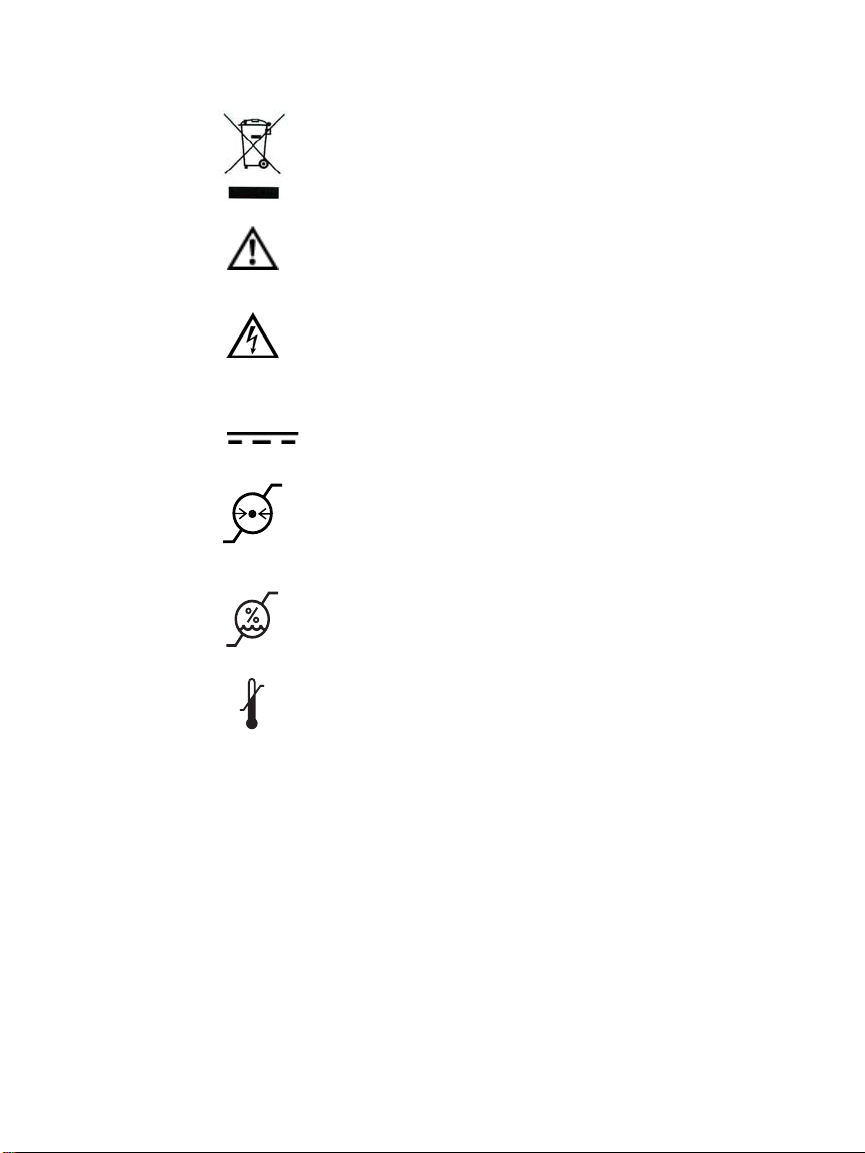
Symbol explanations
DISPOSAL. Do not use household or municipal waste
collection services for disposal of electrical and
electronic equipment. EU countries require the
use of separate recycling collection services.
WARNING/CAUTION. Read the accompanying text
carefully, for proper operation and maintenance of
the display system.
DANGEROUS VOLTAGE. Important precautions about
electric shock. Read the accompanying text carefully,
to prevent damage to components of the display
system and for your safety.
DIRECT CURRENT.
iv | Dome E4c Display
BAROMETRIC PRESSURE.
Maximum operating altitude, up
to 3,048 meters (10,000 feet). Maximum unpressurized
shipping and storage altitude, up to 12,192 meters
(40,000 feet).
RELATIVE HUMIDITY. Operating 10% to 90% (non-
condensing). Transport and storage 5% to 90%
(non-condensing).
TEMPERATURE. Operating 0° to 40° C. (Ambient air
temperature surrounding the display.) Transport and
storage -10° to 60° C. NOTE: After shipping or storage,
allow display unit to reach room temperature before
powering on. Ambient room temperature ranges from
20° to 25° C (68° to 77° F).
Page 5

Intended use
The Dome E4c display is an AMLCD unit designed for viewing medical
X-ray images. This unit should not be used near patients and should
be kept outside of 1.83 m perimeter and 2.29 m vertical.
This device must not be used in primary image diagnosis in
mammography.
CAUTION: Federal law restricts this device to sale by or on the order of
a medical practitioner.
Safety precautions
External equipment intended for connection to signal input, signal
output, or other connectors must comply with the relevant IEC
standard (EN/IEC 60601-1 series for medical electrical equipment).
All such combinations (systems) must comply with the standard IEC
60601-1-1, Safety requirements for medical electrical systems.
Equipment not complying to IEC 60601 must be kept outside the
patient environment, as defined in the standard as at least 1.5 meters
from the patient or the patient support.
Any person who connects external equipment to signal input, signal
output, or other connectors has formed a system and is therefore
responsible for the system to comply with the requirements of IEC
60601-1-1. If in doubt, speak with a qualified technician.
GROUNDING RELIABILITY CAN ONLY BE ACHIEVED WHEN
EQUIPMENT IS CONNECTED TO AN EQUIVALENT RECEPTABLE
MARKED “HOSPITAL ONLY” OR “HOSPITAL GRADE.”
Product Information | v
Page 6

Safety tips
• Use caution when adjusting the position of the display. Improper
handling of the unit may result in hand injury. Always grasp the
sides of the display to adjust the viewing angle, height, or tilt.
• Never place your hands between the display and the stand base
when lowering the display height.
• Never open the display case, even when the power is off. Do not
drop or push objects into the display case. Dangerous voltage
inside may cause electric shock or death.
• Use the grounded power supply and the video cable supplied by
Planar. Replace the power supply or video cable if damaged.
• Be sure the display is electrically grounded. Connect the third
grounding pin on the US power cord to a grounded outlet. The
European power cord lacks a third grounding pin, but it must be
plugged into a grounded outlet. If the power cord connects
directly into the computer, make sure the computer is grounded.
• Keep the display dry if it is part of a surgical system. The display
lacks protection against liquids or spills.
• Do not plug the power supply into an overloaded AC outlet or
extension cord. Overloaded AC outlets and cords can result in
electric shock or fire.
• Unplug the power cord from the wall outlet during
thunderstorms.
• Do not place magnetic devices, such as motors, near the display.
• In locations where 240V outlets are used, connect the
Dome E4c display to a center-tapped, 240V, single-phase
supply only (for Canada and the United States only).
vi | Dome E4c Display
Shipping/storing the display
Keep the display in its shipping container until installation. Return the
display to its original container whenever you need to store the unit,
move it to another location, or return it for repair.
Page 7

Unpacking and handling tips
The Dome E4c display is a precision instrument that requires proper
care to maintain adherence to specification. Unpack the display
carefully, then follow instructions to avoid damage to the LCD panel.
• Use both hands to grasp the display case when lifting it from
the shipping carton, but avoid touching the screen.
• Do not apply pressure to the screen or touch the screen with
bare fingers or objects. Pressure can affect image quality.
• Allow the display to warm to room temperature before turning it
on. Avoid sudden temperature changes to prevent condensation.
• Secure the display onto the Planar-supplied wall or cart mounting
hardware to ensure safety if you elect not to use the desk stand.
• Do not set up the display near strong light or heat sources.
• Do not block the vents on the display or install the display in a builtin enclosure. Blocked vents cause excessive heat inside the display.
• Do not remove the back cover or disassemble the display.
There are no user-serviceable parts inside.
Cleaning the display unit
Periodically wipe the display housing with a soft, dry cloth to prevent
dust and other material from clogging the venting holes.
The display screen can be damaged by excessive scrubbing and by
incompatible cleaning solvents. Dampen a clean, soft lint-free cloth
with distilled de-ionized water and wipe the screen gently. Use a
clean, soft, dry lint-free cloth to remove any residue.
To remove grease or other organic contaminants from the screen,
use a 50% to 70% IPA (isopropyl alcohol) solution sparingly. Never
use acetone, as it can damage the antistatic hard coating.
WARNING
DISCONNECT SUPPLY BEFORE SERVICING
AVERTISSEMENT
COUPER L’ALIMENTATION AVANT L’ENTRETIEN ET LE DEPANNAGE
Product Information | vii
Page 8
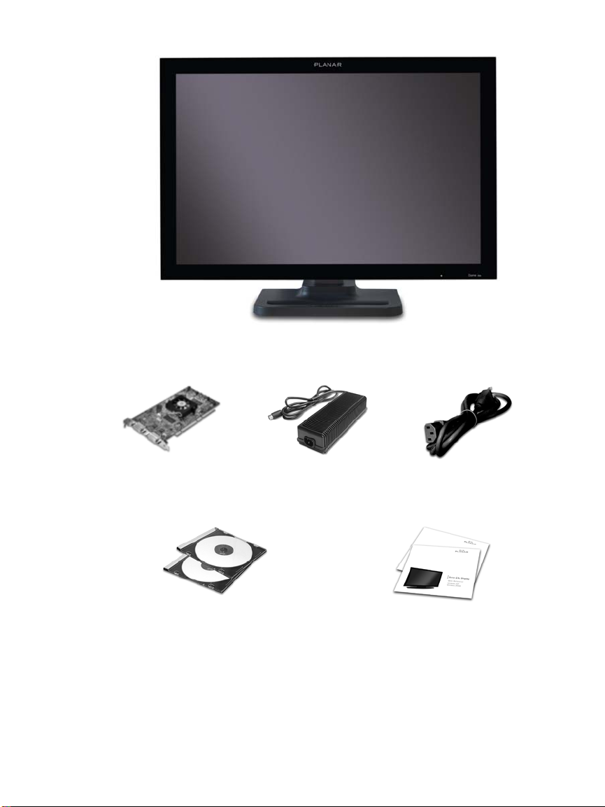
AMLCD panel mounted on desk stand
Graphics display controller
Display driver and
Dome CXtra software
DC power adapter Power cords
Quick references
Options available: VESA wall-mounting kit and Dome Surgery Review Cart.
See page 13 for more information.
Page 9

About the Display
The Dome E4c display is a 30-inch AMLCD color panel designed for
widescreen diagnostic imaging. The combination of high resolution
and high contrast ratio allow the viewing of color and grayscale
images simultaneously.
Bezel-free framing of 4 megapixels of data is presented in a landscape
resolution of 2560 x 1600 pixels. Gamma correction is achieved on
this true color display from a palette of 1786 near-gray values.
The integrated Dome RightLight controller monitors and stabilizes
backlight luminance.
Use of the Dome E4c display with the MX4 graphics display controller
offers these three advantages:
• Graphics board installation for PCI slot
• Dual-display configuration (two boards required)
• Image display in portrait mode
System requirements
• PCI slot (64-bit recommended)
• 50 MB hard disk space
•256 MB RAM
•CD-ROM drive
• Power supply, 350 watts or greater
• Windows XP Service Pack 1 or
Windows 2000 Service Pack 4
•.NET Framework 1.1
Page 10
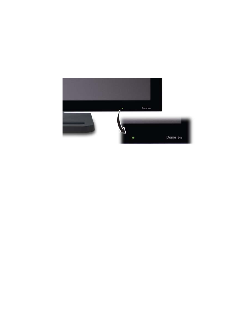
Display status
The Dome E4c display has a light-emitting diode, or LED, on the front
panel to indicate display status.
• Green. The display is connected and running properly.
• Amber. The video signal is not being received.
LED on display front
There is no power switch on the display unit. The unit turns on
automatically when the computer system is turned on. The LED
appears green to indicate functional system, or normal operation.
Improper cable connections could cause no image to appear on the
display screen or the LED to glow amber. See “Troubleshooting” on
page 14 for more information.
2 | Dome E4c Display
Page 11
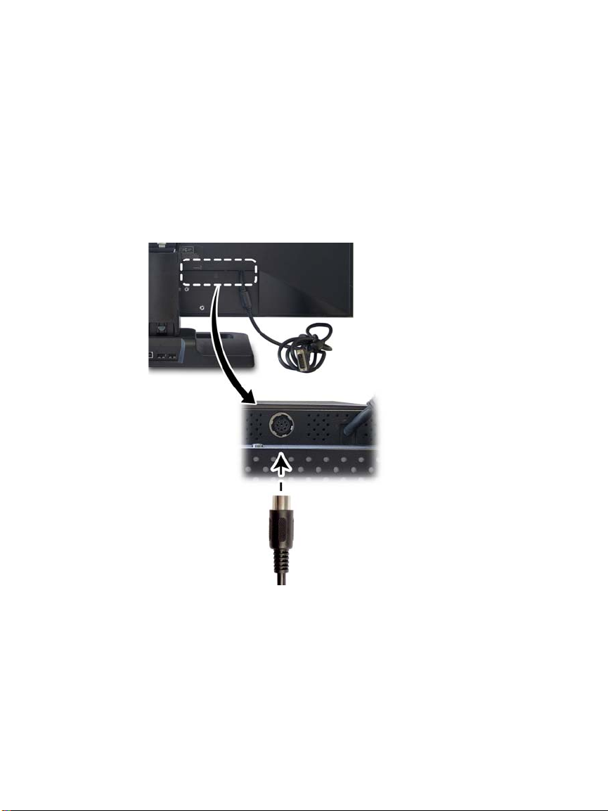
Display power
The power input port is an 8-pin DIN connector that drives power to
the display. See page 17 for the pin assignment.
The dual-link DVI cable drives data to the display and is integrated
into the display unit. When the DVI cable is disconnected from the
graphics board, the display backlight turns off and the unit enters
power-saving mode.
Display brightness and power saving functions are controlled via the
Dome CXtra software. No other user-accessible controls are available.
DIN connector, left
Integrated dual-link DVI cable, right
About the Display | 3
Page 12

Display stand
Improper handling of the display unit may result in hand injury. Use
caution when adjusting the position of the display. Never place your
hands between the display and the stand base when lowering the
height. Avoid holding the bottom area of the display.
Always grasp the sides of the display to adjust the viewing angle, tilt,
and height of the screen.
NOTE: To unlock the stand column, move the lever to the left. You can
only lock the stand column when the display height is in the lowest
position, which is also the shipping/storage position.
4 | Dome E4c Display
The stand includes an integrated USB hub and can be used for
cable management. See page 18 for more information.
Page 13

Swivel the screen left or right to
adjust the viewing angle.
Push the screen backward or
pull it forward to adjust the tilt.
Slide the screen up or down to
adjust the height.
About the Display | 5
Page 14

Display Installation
Before you install the MX4 graphics display controller, remove any
existing graphics board and its driver from your computer. After
installation, the display turns on automatically when you turn on
your computer system.
Safety precautions
In locations where 240V outlets are used, connect the Dome E4c
display only to a center-tapped, 240V, single-phase supply (for
Canada and the United States only).
Turn off your computer before you install the graphics display
controller, but leave the power cord plugged into the grounded
outlet. Otherwise, you could get an electric shock and cause
damage to the components.
To prevent electrostatic discharge, take these precautions:
• Slowly remove the graphics board from its static-shielding bag.
• Wear an antistatic wrist strap.
• Repeatedly touch the power supply or the metal surface of
the computer chassis to discharge your body’s static electricity.
6 | Dome E4c Display
Page 15

To install the graphics board and display
1 Remove the computer cover and the blank bracket from
the available PCI slot.
2 Insert the graphics board into the slot, align the connector pins,
and press the board down until it is firmly seated. Secure the
mounting bracket and reattach the cover.
3Plug the DC power cord into the power input port on the display.
Connect the dual-link DVI cable to the display.
4 Connect the DVI cable to the bottom port of the graphics board
installed in the computer. Plug the AC power cord into the power
adapter and into the grounded power outlet.
See page 6 for illustration of the install procedure.
Installation tip
Both DVI ports function on the graphics board shipped with your
Dome E4c display, but only the bottom port allows you to enable
dual-link functionality. Use the bottom port to support the display
with the full, non-scaled 2560 x 1600 resolution.
DVI port for duallink functionality
MX4 display controller
Display Installation | 7
Page 16

Remove the computer cover and
1 2
the PCI bracket.
Install the graphics board and
reattach the cover.
Connect the power adapter cord to
3
the display.
8 | Dome E4c Display
Connect the DVI cable to the
4
bottom port to enabling dual-link
functionality, then plug the power
cord into a grounded outlet.
Page 17

To install the display driver
Before you install the driver, remove any previously installed display
driver from your system.
1 Start your computer system. Click Cancel on the Found New
Hardware Wizard. Click No to respond to restart prompt.
2 Insert the driver installation CD and click Next.
3 Auto-detection reports the driver version and graphics board(s).
Click Next.
4 Click the check box to enable independent mode for each
graphics card. Click Next.
Dialog for enabling independent mode per graphics card
5 Click Next to continue. File copy begins.
6 Click Continue Anyway on the dialog reporting no digital signature.
Repeat for a second graphics card.
7 Click Next upon completion of the driver installation.
8 Select the Restart computer option and click Finish.
Display Installation | 9
Page 18

To configu re the display
1 Right-click the desktop and select Properties > Settings.
2 Use the native resolution of the display, 2560x1600.
3 For use of the second display, select Extend my Windows desktop
onto this monitor.
4 Click OK until you return to the desktop.
To set brightness
You must have the Dome CXtra software installed to change
the display brightness. Adjust the value of the white level on
the Backlight tab of the RightLight Panel Configuration.
To rotate the display
1 Click the PowerDesk icon on the taskbar. See illustration below.
2 Select Monitor Adjustments on the PowerDesk menu.
3 Select Adjust Orientation.
4 Select the degree of rotation.
5Click Apply or OK.
PowerDesk icon on taskbar
To set up multi-display mode
1 Click the PowerDesk icon on the taskbar.
2 Select Multi-Display Setup on the PowerDesk menu.
3 Select the device and multi-display setup you want to use.
4Click Apply or OK.
10 | Dome E4c Display
Page 19

To change video setting per display
1 Click the PowerDesk icon on the taskbar.
2 On the PowerDesk menu, select the graphics card representing the
display you want to change video settings on, then select Grayscale
Setup category. NOTE: Grayscale mode is the installation default.
PowerDesk menu
3 Select one of the options.
– Use Color (RGB mode)
– 256 (Grayscale mode)
When using the grayscale mode, be sure to select the fixed linear
gray palette.
4Click Apply or OK.
5 Restart the system.
NOTE: You must restart the system each time you change the video
settings of a display. For dual configurations, change the settings of
the first display and restart the system, then change the settings of
the second display and restart.
Display Installation | 11
Page 20

To install Dome CXtra
Bundled with the display system, the Dome CXtra software enhances
the functionality of the Dome E4c display with a range of value-added
services, such as DICOM calibration, error reporting, and backlight
saver. Network management of Dome displays running the Dome
CXtra software require the Enterprise Management Service for
Dome CXtra. For more information and instructions on installation,
refer to Dome CXtra User’s Guide.
To conserve energy use
You have two ways to lower energy usage when the display is idle:
• Dome CXtra Backlight Saver service (preferred)
• Screen Saver (set via Windows operating system)
Activate the power saver when you anticipate periods of inactivity,
such as at the end of the work day or work week. Once activated,
Backlight Saver (or Screen Saver) automatically turns the backlight off
during the period of inactivity. Backlight Saver and Screen Saver both
extend the life of the backlight and reduce the burn-in of images.
Do not use the Backlight Saver and Screen Saver concurrently.
To remove the driver
1 Close all applications that are running.
2 Navigate to the Control Panel. Select Add/Remove Programs.
3 Select your current display drivers. Select Add/Remove. Follow
the wizard to remove your current display drivers.
4 Restart your system.
12 | Dome E4c Display
Page 21

Options available
The following options are available for the Dome E4c display.
• VESA (100 mm x 200 mm) wall-mounting kit
• Dome Surgery Review Cart
WARNING: Use only the mounting devices supplied by Planar to
attach the display to the wall unit or to the cart. Failure to use the
specified device or to follow the mounting instructions exactly
could be hazardous.
Display Installation | 13
Page 22

Troubleshooting
Problem Possible Cause Solution
Display does not light up. Power is not on. Make sure that the computer
is turned on.
Activate the computer from
sleep mode.
Power cord is not securely
connected.
No image appears on
the screen
No dual-link functionality. Improper connection. Make sure that DVI cable
Power LED is amber. Video cable is not securely
Video cable is not securely
connected.
fastened.
Tighten power cord
connection and turn on
computer.
Check to see that all cables
are properly connected to
the computer and to the
display.
is connected to the bottom
port on the graphics board.
Turn off the computer. Make
sure that the video cable is
properly connected to the
display and to the graphics
board.
Check the computer power
and graphics board
configuration.
14 | Dome E4c Display
Page 23

Specification
In locations where 240V outlets are used, connect the Dome E4c display only to a centertapped, 240V, single-phase supply (only for Canada and the United States).
Category Characteristic Item Specification
Screen Screen size diagonal 756.228 mm (30 in.)
Resolution 2560 x 1600 pixels (landscape)
Pixel pitch 0.2505 mm, 101 dpi
Pixel arrangement RGB vertical stripe
Active area 641.28 mm x 400.8 mm (25.25 in. x 15.78 in.)
Number of colors supported 16.7 million colors, 256 shades of gray from
a palette of 1786 near-gray shades
Refresh rate 60 Hz
Contrast ratio 600:1 (typical)
Brightness 300 cd/m
330 cd/m
Pixel rise/fall time 14 ms typical Black-White
11 ms typical Gray-Gray
Viewing angle ± 85° (170°) horizontal
Interface Digital Video In DVI Rev. 1.0 digital dual-link connector
Display control –
Brightness/contrast
Display identification EDID read using DDC2B+
Display status LED on front of unit
Input formats Landscape orientation 2560 x 1600 (24-bit color)
VGA/XGA 640 x 480 –1280 x 800
Physical Screen type AMLCD (active matrix liquid crystal display)
Protective glass Antistatic hard coating (3H)
Display size (without stand) 713 mm x 473 mm x 72 mm
Display weight (without stand) 12.7 kg (28 lb)
Mounting options Desktop stand (standard);
Power Adapter JEC Korea Corporation, Type JMW1150KA2423F51
± 85° (170°) vertical
DDC2B+
(28.0 in. x 18.6 in. x 2.8 in.) nominal
100 mm x 200 mm VESA wall mount (optional)
CAUTION: Use only the power adapter supplied
with the display unit.
2
(typical) – protective glass model
2
(typical) – open bezel model
Specification | 15
Page 24

Power supply
CAUTION: Use only the power adapter supplied with the Dome E4c display unit
(JEC Korea Corporation, Type JMW1150KA2423F51).
Category Characteristic Item Specification
Power input
requirements
Power output
requirements
Physical Size 223.5 mm x 90 mm x 56.6 mm
Voltage selection Auto-ranging
Voltage 100 – 240V AC
Current 3.0 A
Frequency 50 to 60 Hz
Voltage 24 V DC
Current 6.25 A (150 W)
(8.8 in x 3.5 in x 2.2 in)
Weight 1.4 kg (3 lb)
±5%
Reliability
Characteristic item Specification
Display MTBF >50,000 hours
Backlight MTBF 50,000 hours typical
Environment
Characteristic item Specification
EMI shielding No emission of low-level radiation
Temperature operating 0° C to 40° C
storage -10° to 60° C
Humidity operating 10% to 90% Relative Humidity
(non-condensing)
storage 5% to 90% Relative Humidity
(non-condensing)
16 | Dome E4c Display
Page 25

Connector ports
The power input port is an 8-pin DIN connector. The power input is
24V ±5% (115 W typical).
Input power port
Display screen face down
Pin assignment of DIN connector
VCC 8
VCC 7
1 GND
VCC 6
VCC 5 3 GND
4 GND
2 GND
8-pin DIN connector
Specification | 17
Page 26

Desktop stand
Unfasten the stand lock when necessary to adjust display height.
Move the lever to the left to unlock the stand column.
Remove the stand cable cover to thread the power cord and DVI
cable to the display. Press the PUSH button above the USB hub then
pull the cover down and out to remove it. Thread the DVI cable and
the power cord through the back of the stand. Make sure the cable
and cord are seated in the notches. To reattach the stand cover, align
the hooks with the slots on the stand. Press the cover into place. A
click sound signals a secure connection.
Use the integrated, bus-powered USB hub to attach USB devices
to the display instead of the computer. To activate the USB hub
function, the display must be connected to a USB-compliant
computer or another hub with a USB cable. Even if the display is in
power-saving mode, the USB devices function when connected to
the USB ports on the stand.
Lock lever
Display desktop stand
18 | Dome E4c Display
Stand cable cover
PUSH button
USB hub
Page 27

Regulatory Compliance
Canada, European Union, United States
This display has been tested and
found to comply with IEC/EN
60601-1 and IEC/EN 60601-1-2
standards, and is certified to
meet medical standard C22.2
No. 601.1-M1990 (C US Mark).
The medical display, in addition to meeting medical requirements, has been
tested and found to comply with the limits for Federal Communications
Commission (FCC) Class B computing devices in a typically configured system
since many medical offices are located in residential areas. It is the system
integrator’s responsibility to test and ensure that the entire system complies
with applicable electromagnetic compatibility (EMC) laws.
Planar Systems, Inc. has made great efforts to support the medical device
industry, in particular, medical device manufacturers and medical device
system integrators. We offer state-of-the-art color displays that are compliant
with worldwide accepted medical device safety standards, and for the
European market, CE-marked displays based on compliance with counsel
directive 93/42/EEC—commonly referred to as the Medical Device Directive
(MDD). The following summarizes our qualification of these displays as it
relates to compliance with the MDD.
The European Medical Device Directive requires that the intended use of the
device be defined. The intended use of these displays is “to display
alphanumeric, graphic, and image data as inputted from any type of medical
device.” These displays do not provide a measurement function in any way,
and it is the device and systems manufacturer’s responsibility to verify its
function in the integrated device or system.
The display was classified as required by the MDD according to Annex IX of
the directive and the medical device (MEDDEV) guidance available at the time
of classification. Because the display uses electrical energy and has no direct
patient connections and—by itself—no medical utility, the display is
classified according to Rule 12 as an MDD Class I device, component, or
accessory. The MDD states that manufacturers of Class I medical devices or
accessories shall satisfy the requirements in regard to design and
manufacturing controls, that is, the applicable assessment route to be used
for CE-marking under the MDD, and it shall carry the CE mark according to
Annex XII of the directive, with no notified body annotation.
Page 28

The applicable safety standards for an MDD Class I display are IEC/EN
60601-1:1990 along with Amendments 1 and 2. To help the medical device
designer evaluate the suitability of these displays, Planar has also conducted
EMC testing to IEC 60601-1-2 as it can be applied. The display with its power
supply alone does not represent a functional medical device. Hence, Planar
configured a minimal operating system to exercise the display. The resulting
data are made available to interested parties.
This is informative data, not certification data. Certification data must
be obtained by the device or system integrator according to Article 12 of
the MDD titled “Particular procedure for systems and procedure packs.”
Paragraph 2 clearly outlines the device or system integrator’s responsibility in
this matter.
In summary, Planar Systems, Inc. is CE-marking these displays under the
Medical Device Directive, which establishes compliance to the basic medical
safety standards. However, EMC compliance can only be accomplished in the
configured medical device or system and is the responsibility of the device or
system manufacturer. Planar has the necessary documentation such as IEC
60601-1 notified body and other third-party test reports and certifications, a
risk/hazard analysis, an essential requirements checklist, and the Planar
International Electrotechnical Commission (IEC) declaration of conformity.
Planar Systems, Inc., located in Beaverton, Oregon, USA, is the manufacturer
of these displays in the meaning of the directive. As required by the MDD in
Article 14, Planar Systems, Inc., not residing in the European Economic Area
(EEA), has a European representative, Planar Systems, Inc.—Olarinluoma 9,
P. O. Box 46, FIN-02201 Espoo, Finland (phone + 358 9 420 01;
fax + 358 9 420 0200).
In the opinion of Planar Systems, Inc. registration required to put this
device into commerce is the responsibility of the medical device/system
manufacturer, and Planar supports this requirement by providing a European
Commission (EC) declaration of conformity. If Planar supplies a display to an
end user, rather than a device manufacturer, it is the end user’s responsibility
to ensure continued compliance with the MDD of the system in which the
display is integrated.
The supplier will make available on request, circuit diagrams, component
part lists, etc.
For vigilance reporting as required under Article 10 of the MDD, Planar
Systems, Inc. will provide any information requested by competent authority
to support any reported incident investigation by such an authority.
Page 29

EU Declaration of Conformity for Medical Application
A Declaration of Conformity has been filed for this product. For
additional copies of the Declaration of Conformity document,
contact Planar Systems.
The Dome E4c digital flat-panel display meets the essential health
and safety requirements, is in conformity with, and the CE marking
has been applied according to the relevant EU Directives listed below,
using the relevant section of the following EU standards and other
normative documents;
EU EMC Directive 89/336/EEC
EU Electromagnetic Compatibility Directive
EN 60601-1-2 (2001)
Medical Electrical
Equipment
EN 55011 (Class B) Limits and methods of measurements for radio
IEC 1000-3-2 Harmonic emissions
IEC 1000-3-3 Voltage fluctuations/flicker emissions
IEC 1000-4-2 Electrostatic discharge requirements for industrial
IEC 1000-4-3 Radiated electromagnetic field requirements for
IEC 1000-4-4 Electrically fast transients for industrial process
IEC 1000-4-5 Surge requirements
IEC 1000-4-11 Voltage variations/dips/interrupts
IEC 1000-4-6 Conducted immunity
IEC 1000-4-8 Magnetic field immunity
EN 60601-1 Medical
Electrical
Equipment
Section 1.2. Collateral standard electromagnetic
compatibility requirements
interference characteristics of industrial, scientific,
and medical equipment
process measurement and control equipment
industrial process measurement and control
equipment
measurement and control equipment
Conformance to the Medical Device Directive 93/
42/EEC
Part 1: General requirements for safety
Page 30

U.S. FCC Compliance Statement
Display Unit
This device complies with Part 15 of the FCC Rules.
Operation is subject to the following two conditions:
(1) This device may not cause harmful interference, and (2) this device
must accept any interference received, including interference that
may cause undesired operation.
NOTE: This equipment has been tested and found to comply with the
limits for a Class B digital device, pursuant to Part 15 of the FCC Rules.
These limits are designed to provide reasonable protection against
harmful interference in a residential installation. This equipment
generates, uses, and can radiate radio frequency energy and, if not
installed and used in accordance with the instruction, may cause
harmful interference to radio communications. However, there is no
guarantee that interference will not occur in a particular installation. If
this equipment does cause harmful interference to radio or television
reception, which can be determined by turning the equipment off
and on, the user is encouraged to try to correct the interference by
one or more of the following measures:
• Reorient or relocate the receiving antenna.
• Increase the separation between the equipment and receiver.
• Connect the equipment into an outlet on a circuit different from
that to which the receiver is connected.
• Consult the dealer or an experienced radio/TV technician for help.
CAUTION: Changes or modifications to this equipment not expressly
approved by the party responsible for compliance could void the
user’s authority to operate the equipment.
Graphics Adapter
The MX graphics display controller included in this product has been
tested and listed to comply with FCC Class A by the manufacturer.
To be compliant with FCC requirements, the configured system
utilizing the display and the graphics board must be tested by the
integrator to ensure that the entire system complies with FCC Class B.
Page 31

Australian
China
Japan
Korea
Taiwa n
Australian Communications Authority regulating
product EMC compliance.
China Compulsory Certification regulating safety and
EMC.
GB4943-2001
GB9254-1998 (Class A)
CB17625.1-2003
Voluntary Control Council for Interference by
information technology equipment sold in Japan.
Ministry of Information and Communications.
Bureau of Standards, Metrology and Inspection.
Page 32

Standard Warranty
Summary
• Standard one-year “repair-and-return” warranty
•Two-year backlight warranty
• Typical repair turnaround time of 10 business days
Standard Warranty Return Procedure
As a Planar Standard Warranty customer, you must follow the procedure below if
you have a non-functioning Dome E4c display. The Planar customer service staff will
attempt to correct any minor issues that may be causing the problem. Once Planar has
determined that you have a non-functioning product, Planar will arrange for return and
repair of the non-functioning product.
1 Contact Planar via the web at http://www.planar.com/support. In North America,
call (866) PLANAR1 (866.752.6271). In Europe, call +358 9 420 01 or send your info by
fax to +358 9 420 0200. Have the model number, serial number, and proof-ofpurchase available.
2 Planar customer service staff will attempt to correct any minor issues that may be
causing the problem. If we are unable to correct the problem to your satisfaction, we
will issue a Return Material Authorization (RMA).
3 You must return the product, as specified, to Planar Systems. Planar will validate the
defect, repair the unit, and return the unit to you. The typical turnaround time is
10 business days.
*
* If, within 2 years of initial purchase, the maximum output of the Dome E4c
display is determined by Planar Systems to be less than 175 cd/m
repair or replace the display at its sole discretion.
2
, Planar will
Page 33

Summary Limitations and Exclusions of Dome Displays
1 Customer must provide original proof of purchase of the display system.
2 Warranty is void on any product with a defaced, modified, or removed
serial number.
3 Warranty is void on any product with damage, deterioration, or malfunction
resulting from the following:
a) Accident, misuse, neglect, fire, water, lightning, or other acts of nature,
unauthorized product modification, or failure to follow instructions supplied with
the product.
b) Repair or attempted repair by anyone not authorized by Planar.
c) Any damage of the product due to shipment.
d) Removal or installation of the product.
e) Causes external to the product, such as electric power fluctuations or failure.
f) Use of supplies or parts not meeting Planar's specifications.
g) Normal wear and tear.
h) Any other cause, which does not relate to a product defect.
4 Warranty excludes removal, installation, and setup service charges.
Limitation of Implied Warranties
THERE ARE NO WARRANTIES, EXPRESS OR IMPLIED, WHICH EXTEND BEYOND THE
DESCRIPTION CONTAINED HEREIN INCLUDING THE IMPLIED WARRANTY OF
MERCHANTABILITY AND FITNESS FOR A PARTICULAR PURPOSE.
Exclusion of Damages
THE LIABILITY OF PLANAR IS LIMITED TO THE COST OF REPAIR OR REPLACEMENT OF
THE PRODUCT. PLANAR SHALL NOT BE LIABLE FOR THE FOLLOWING:
1 DAMAGE TO OTHER PROPERTY CAUSED BY ANY DEFECTS IN THE PRODUCT,
DAMAGES BASED UPON INCONVENIENCE, LOSS OF USE OF THE PRODUCT, LOSS OF
TIME, LOSS OF PROFITS, LOSS OF BUSINESS OPPORTUNITY, LOSS OF GOODWILL,
INTERFERENCE WITH BUSINESS RELATIONSHIPS, OR OTHER COMMERCIAL LOSS,
EVEN IF ADVISED OF THEIR POSSIBILITY OF SUCH DAMAGES.
2 ANY OTHER DAMAGES, WHETHER INCIDENTAL, INDIRECT, CONSEQUENTIAL OR
OTHERWISE.
3 ANY CLAIM AGAINST THE CUSTOMER BY ANY OTHER PARTY.
Effect of Local Law
This warranty gives you specific legal rights, and you may have other rights, which vary
from locality to locality. Some localities do not allow limitations on implied warranties
and/or do not allow the exclusion of incidental or consequential damages, so the
above limitations and exclusions may not apply to you.
Page 34

America Sales
Planar Systems, Inc.
1195 NW Compton Drive
Beaverton, OR 97006-1992 USA
(503) 748-1100 phone
(503) 748-1493 fax
Medical Sales
Planar Systems, Inc.
400 Fifth Avenue
Waltham, MA 02451-8738 USA
(781) 895-1155 phone
(781) 895-1133 fax
medicalsales@planar.com
medicalsupport@planar.com
www.planar.com
Europe & Asia-Pacific Sales
European Representative
Planar Systems, Inc.
Olarinluoma 9, P. O. Box 46
FIN-02201 Espoo, Finland
+ 358 9 420 01 phone
+ 358 9 420 0200 fax
vertrieb@planar.com
medicalsupport@planar.com
www.planar.com
Asia-Pacific Sales
Planar Systems, Inc.
388 Nan Jing West Road, Suite 3905
Shanghai Peoples Republic of China
+ 86 21 6334 5050 phone
+ 86 21 6334 6339 fax
sales @planar.com.cn
support@planar.com.cn
www.planar.com.cn
 Loading...