

Page 1
Operations Manual
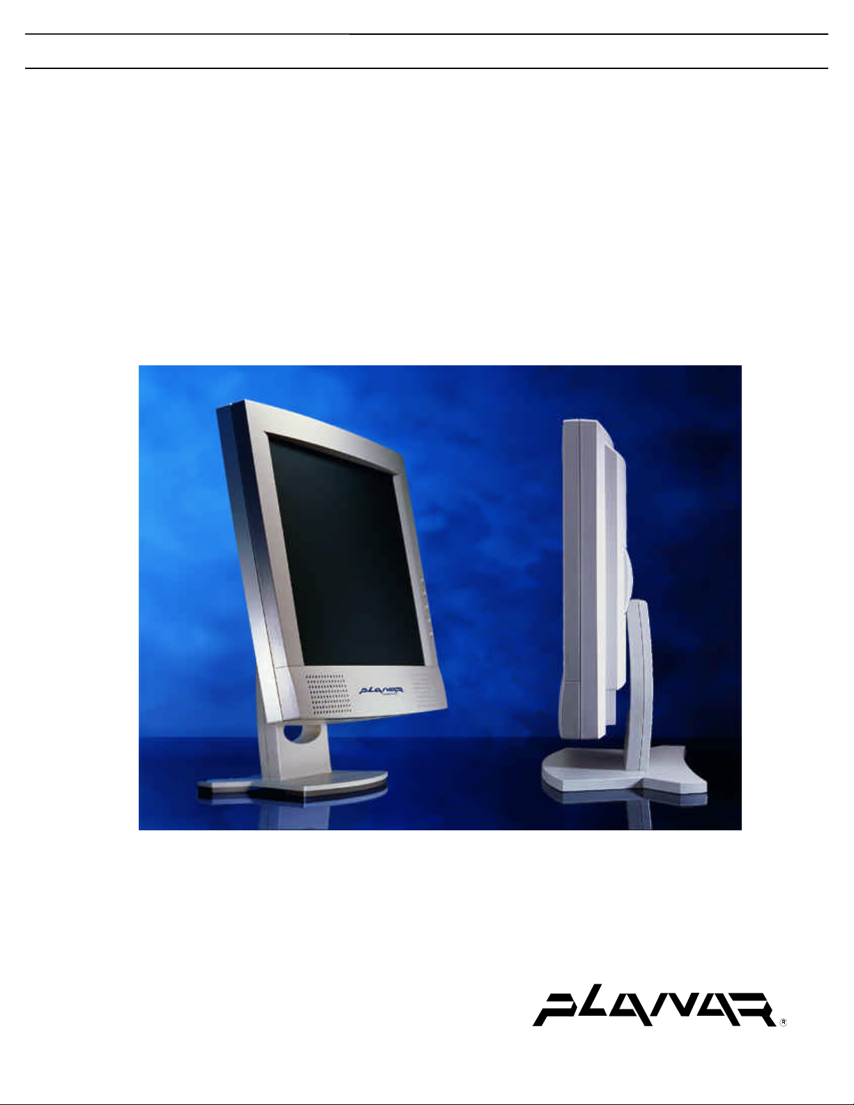
D6015TM SERIES MEDICAL MONITOR
D6015TM 15" XGA
D6015TM;TS 15" XGA, SAW TOUCHSCREEN
D6015TM;TR 15" XGA, RESISTIVE TOUCHSCREEN
The Definition of Quality
Page 2

Planar Systems, Inc. © 2000
“Planar” and “The Definition of Quality” are registered trademarks of Planar Systems, Inc. “ELO” is a
registered trademark of Elo TouchSystems, Inc., “GCX” and “GCX Instrument Mounting Systems” are
registered trademarks of GCX Corporation. All other trademarks are the property of their respective
owners.
This document is subject to change without notice. Planar provides this information as reference
only. Reference to other vendors’ products does not imply any recommendation or endorsement.
Revision Control
Date Description
July 2000 Document number OM700-02 (020-0151-00 Rev. C)
Page 3

Contents
Planar D6015TM Series Medical Monitor........................................................1
Functional Description.................................................................................................1
Product Features ..........................................................................................................2
Cleaning Instructions ...................................................................................................2
Safety Instructions........................................................................................................3
Disposal Information....................................................................................................3
Symbol Explanations ...................................................................................................4
Regulatory Compliance................................................................................................4
EU Declaration of Conformity for Medical Applications.....................................5
Installation............................................................................................................ 6
Identifying Components...............................................................................................7
Front View............................................................................................................7
Rear View .............................................................................................................8
Connecting the Optional Touchscreen.........................................................................9
Positioning...................................................................................................................9
Adjusting the Viewing Angle.....................................................................................10
Connecting AC Power................................................................................................10
Connecting Video ......................................................................................................11
Connecting Optional Stereo Speakers........................................................................11
Power Management System.......................................................................................12
The Display Controls.........................................................................................13
Adjusting the Medical Monitor’s Display..................................................................14
On-Screen Display Lockout................................................................................14
OSD Main Menu.................................................................................................15
Quick Adjustment Functions......................................................................................17
Power Switch.............................................................................................................17
Technical Information.......................................................................................18
Planar D6015TM Series Medical Monitor Specifications.........................................18
Video Modes..............................................................................................................19
Connectors.................................................................................................................20
DC Input.............................................................................................................20
Video Input .........................................................................................................20
Audio Port...........................................................................................................20
Touch Port..........................................................................................................20
Mechanical Outline Drawings.......................................................................... 21
Troubleshooting Procedures............................................................................. 23
PROBLEM: No Signal Coming ..........................................................................23
PROBLEM: Display is Unclear and Unstable ...................................................23
PROBLEM: Signal Over Supported Range........................................................24
PROBLEM: There is No LCD Display...............................................................24
Description of Warranty................................................................................... 25
Commencement and Duration of Warranty........................................................25
Place of Repair or Replacement.........................................................................25
Limitation of Warranty .......................................................................................25
Installation..........................................................................................................26
Technical Assistance...........................................................................................26
Repair Service.....................................................................................................26
Ordering Information ....................................................................................... 27
Figures
Operations Manual (OM700-02) i
Page 4

Figure 1: Controls and Front View..............................................................................7
Figure 2: Monitor, Rear Ports......................................................................................8
Figure 3: Connecting the Optional Touchscreen Cable ...............................................9
Figure 4: Screen Angle Settings.................................................................................10
Figure 5: Connecting Power to the Monitor...............................................................10
Figure 6: Connecting the Monitor to Your System....................................................11
Figure 7: Connecting the Stereo Speakers.................................................................11
Figure 8: Monitor Display Controls...........................................................................13
Figure 9: Buttons to Press for OSD Lockout .............................................................14
Figure 10: The OSD Main Menu...............................................................................15
Figure 11: GCX/VESA Mounting Option .................................................................21
Figure 12: Desk Stand Option....................................................................................22
ii Operations Manual (OM700-02)
Page 5

Planar D6015TM Series Medical Monitor
The Planar D6015TM Series Medical Monitor is a 15-inch XGA monitor
designed to be versatile, ergonomic, and easy to use. It is capable of displaying
most video standards from 640x480 (VGA) to 1024x768 (XGA). The digital
controls located on the front panel allow you to easily adjust the monitor’s
display parameters using the On-Screen Display (OSD) menus.
Using either a VESA/GCX Instrument Mounting System or compatible
mounting plate or an optional desk stand, the monitor’s small footprint allows
you more room in your workspace for other peripherals. The two stereo speakers
let you further expand your computer’s multimedia capabilities by connecting
your system’s audio-out port to the monitor’s audio-in port.
The architecture of the Planar D6015TM Series Medical Monitor incorporates
an active matrix LCD (AMLCD) panel that produces a clear display with low
radiation emission, greatly reducing the radiation-related health concerns
associated with CRT monitors.
Functional Description
The Planar D6015TM Series Medical Monitor consists of a low-profile molded
plastic monitor head, video and audio cables, and a power supply. Options
include a Surface Acoustic Wave or Resistive touchscreen with interface cable.
The display shows 262,144 colors with a pixel matrix of 1024 columns by 768
rows.
The monitor is compatible with standard analog computer video signals. It is
connected to the host computer through a standard 15-pin VGA connector on the
bottom of the monitor.
The monitor automatically adjusts to applied video and synchronization signals
to provide a stable, centered display. Additionally, user controls for brightness
and tuning are located on the front of the monitor.
The monitor is certified by TÜV Rheinland according to IEC/EN60601-1:1990
+A1 + A2 for sale to the medical market. The monitor is certified by CSA
International to medical standards C22.2 No. 601.1-M1990 (C US Mark)
(equivalent to UL2601). The monitor is also CE marked for sale into the
European Community for integration or use with medical products.
Operations Manual (OM700-02) 1
Page 6

Product Features
• Display Type: Color Active Matrix LCD
• Control Buttons:
− Function select up and Function select down ( and )
− Adjustment increase and Adjustment decrease ( and )
− Power on/off ( )
• Adjust speaker volume directly with the Adjustment increase/decrease
buttons.
• Indicators:
− On-Screen Display “OSD” function
− Power LED indicator is lit when the monitor is on and blinking when the monitor
• Display Formats:
− VGA, SVGA, and XGA
− VESA DDC1 and DDC2B Plug and Play Functions
− NEC PC98
− APPLE MAC
− 1024x5l2 (special)
is in power-save/standby mode
Cleaning Instructions
The D6015TM Series Monitors will continue to operate normally while being
cleaned in a fashion normal for a hospital environment. This includes cleaning
with a damp (wrung out), mild soapy cloth. Protection from various chemicals
used for cleaning, and protection from liquids consistent with these cleaning
procedures is provided in accordance with IPX1 rating per IEC/EN60529.
The D6015TM Series Monitors will withstand non-abrasive cloths and cleaning
solutions used in hospitals for like equipment. This is typically warm water and
mild detergent for all surfaces or 70% IPA for the touchscreen surface. Possible
chemicals include:
• 70% isopropyl alcohol
• 1.6% aqueous ammonia
• Cidex (2.4% glutaraldehyde solution)
• Sodium Hypochlorite (bleach) 10%
• “Green soap” USP
• 0.5% Chlorhexidine in 70% isopropyl alcohol
• Ovation®
• Formula 409®
• Fantastic®
• WexCide®
To clean the screen, do not spray liquid cleaners directly onto the unit. Stand away
from the monitor and spray cleaning solution onto a cloth. Without applying
excessive pressure, clean the screen with the slightly dampened rag.
2 Operations Manual (OM700-02)
Page 7

Safety Instructions
• Do not place your monitor near a window. Exposing the monitor to rain, water,
moisture, or constant direct sunlight can severely damage it.
• Do not place anything on top of the monitor-to-computer signal cord. Make sure the
cord is placed in an area where it will not be stepped on.
• Do not apply excessive pressure to the screen. Excessive pressure may cause
permanent damage to the display.
• The monitor and power supply units have no user serviceable parts inside. Refer all
servicing to qualified personnel to maintain warranty.
• When using the monitor with the desk stand option, it must be placed on a flat
surface that is horizontal to ±5°.
• Do not cover or obstruct the venting holes on the back of the monitor.
• Store the monitor within -20° to +65° Celsius. Storing your monitor outside this
range could result in permanent damage. Please store in the original shipping carton.
• If any cord or cable is frayed or damaged, immediately replace it with a another of
the same type and rating as supplied by Planar. See “Ordering Information” for part
numbers. Safety and regulatory listings and certifications do not apply if other
cables are used.
• If the monitor has been exposed to liquid, or it has been dropped, or the case has
been damaged, it may pose a shock or fire hazard; immediately unplug it and
contact customer service for assistance.
• Use only Planar Power Adapter (model PPA4512UM) which has been tested and
approved for use with this monitor product. See “Ordering Information” for part
numbers.
Caution: AC Adapter must be plugged into a GROUNDED power outlet.
• When cleaning the power adapter, use a cloth dampened with liquid cleaners on the
outside of the enclosure only. Do not immerse product in liquid or a safety hazard
could arise during use.
• Do not use the power adapter in the presence of flammable anesthetics.
Disposal Information
This monitor contains cold cathode fluorescent lamps which contain a maximum of
12 mg (3 mg per lamp) of mercury. Please follow local ordinances or regulations for
its disposal.
Operations Manual (OM700-02) 3
Page 8
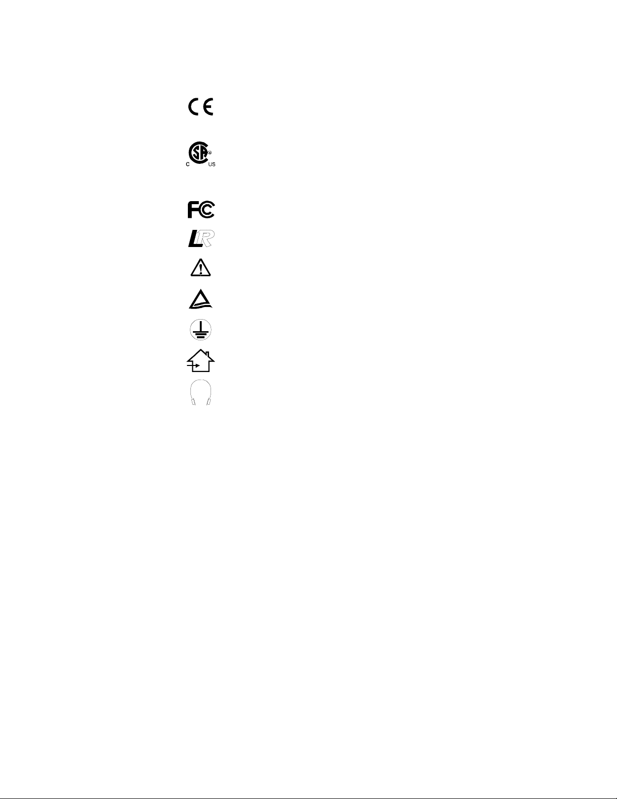
Symbol Explanations
Following are explanations of the symbols found on the monitor or power supply.
Indicates proof of conformity to applicable European Economic
Community Council directives and to harmonized standards
published in the official journal of the European Communities.
Tested and certified by CSA to C22.2 N0. 601.1-M1990. If this
mark appears with the indicators “C” and “US” the product is
certified for both the U.S. and Canadian markets, to the applicable
U.S. and Canadian standards.
Tested to comply with FCC Class B standards.
Indicates that the monitor has been designed to meet low radiation
standards.
Consult accompanying documents.
Tested and certified by TÜV Rheinland in accordance with
EN60601-1.
Indicates protective earth ground.
For indoor use only.
Identifies the socket for headphones.
Regulatory Compliance
This monitor has been tested to comply with IEC/EN 60601-1 and IEC/EN 60601-1-2
by TÜV Rheinland and is certified by CSA International to medical standards C22.2
No. 601.1-M1990 (C US Mark).
Because many medical offices are located in residential areas, this monitor, in addition
to the medical requirements, has also been tested and found to comply with the limits
for FCC Class B computing devices in a typically configured system. It is the system
integrator or configurer’s responsibility to test and ensure that the entire system
complies with applicable EMC laws.
Planar Systems, Inc. has made great efforts to support the medical device industry, in particular
medical device manufacturers and medical device system integrators. We offer state of the art color
displays that are compliant with worldwide accepted medical device safety standards, and for the
European market, CE-marked displays based on compliance with council directive 93/42/EEC –
commonly referred to as the Medical Device Directive (MDD). The following is a summary of our
qualification of these displays as it relates to compliance with the MDD.
The European Medical Device Directive requires that the intended use of a device be defined. The
intended use of these displays is “to display alpha numeric, graphic and image data as inputted from
any type of medical device.” These displays do not provide a measurement function in any way and
it is the device/systems manufacturer’s responsibility to verify its function in the integrated device
or system.
The display was classified as required by the MDD according to Annex IX of the directive and
the MEDDEV guidance available at the time of classification. Because the display uses electrical
energy and has no direct patient connections and – by itself – no medical utility, the display is
4 Operations Manual (OM700-02)
Page 9

classified according to Rule 12 as an MDD Class I device – component or accessory. The MDD
sets out that manufacturers of Class I medical devices or accessories shall satisfy the
requirements in regards to design and manufacturing controls, i.e. the applicable assessment
route to be used for CE-marking under the MDD and shall carry the CE-mark according to Annex
XII of the directive, with no notified body annotation.
The applicable safety standards for a MDD Class I display are IEC/EN 60601-1: 1990 along with
Amendments 1 & 2. To help the medical device designer evaluate the suitability of these
displays, Planar has also conducted EMC testing to IEC 60601-1-2 as it can be applied. The
display with its power supply alone do not represent a functional medical device. Hence, Planar
has configured a minimal operating system that exercised the display. The resulting data is made
available to interested parties.
This data is informative data, not certification data. Certification data must be obtained by the
device or system integrator according to Article 12 of the MDD titled “Particular procedure for
systems and procedure packs”. Paragraph #2 clearly outlines the device or system integrator's
responsibility in this matter.
In summary, Planar Systems, Inc. is CE-marking these displays under the Medical Device
Directive which establishes compliance to the basic medical safety standards. However, EMC
compliance can only be accomplished in the configured medical device or system and is the
responsibility of the device or system manufacturer. Planar has the necessary documentation such
as IEC 60601-1 notified body and other third party test reports and certifications, a risk/hazard
analysis, an essential requirements checklist, and Planar’s EC declaration of conformity.
Planar Systems, Inc. located in Beaverton, Oregon – USA is the manufacturer of these displays in
the meaning of the directive. As required by the MDD in Article 14, Planar Systems, Inc. not
residing in the EEA, has a European Representative, Planar Systems, Inc. – Espoo, Finland.
It is the opinion of Planar Systems, Inc. that registration of putting into commerce is the
responsibility of the medical device/system manufacturer and Planar supports this requirement by
providing an EC declaration of conformity. If Planar supplies a display to an end user, rather than
a device manufacturer, it is the end users responsibility to assure continued compliance of the
system in which the display is being integrated with the MDD.
For Vigilance reporting as required under Article 10 of the MDD, Planar Systems, Inc. will
provide any information requested by a competent authority to support any reported incident
investigation by such an authority.
EU Declaration of Conformity for Medical Applications
A Declaration of Conformity has been filed for this product. A sample of this
document may be found in the addendum which accompanied this manual. For a copy
of the Declaration of Conformity document, please contact Planar Systems, Inc. and
request document number 001-0014-00 “Declaration of Conformity”.
Operations Manual (OM700-02) 5
Page 10

Installation
Before you unpack your monitor, prepare a suitable workspace. You need a
stable and level surface near a grounded wall outlet in an area which is relatively
free of glare from sunlight or other sources of bright light. The monitor is cooled
by natural convection (it has no fan). For optimum performance, do not block the
cooling vents.
While unpacking the monitor, inspect it and other package contents for shipping
damage that could cause a fire or shock hazard. Immediately report any shipping
damage to the carrier or transportation company and contact customer service for
assistance. Keep all packing material in case you need to ship or store the
monitor in the future or in case of return.
After you unpack the monitor, make sure the following items are included (refer
to “Ordering Information” for part numbers):
• Monitor with 1.5 meter (5 ft.) monitor-to-computer video cable
• 1.5m (5 ft.) stereo audio cable
• AC adapter with cable. (CAUTION: AC Adapter must be plugged into a
GROUNDED power outlet.) Output power: 12Vdc to a 4 pin male locking
mini-din connector.
• Power cord (medical grade) which connects from AC mains to AC adapter.
• Touchscreen cable if monitor has touchscreen option.
• This operations manual
Note: Your system provider may offer alternative cords or cables
depending on the installation requirements and local geography issues.
6 Operations Manual (OM700-02)
Page 11

Identifying Components
Front View
1. Monitor Screen
The screen is capable of producing most display standards from 640 x 480 VGA
to 1024 x 768 XGA. A VESA mounting plate (not shown) is secured to the rear
of the monitor and is compatible with GCX Instrument Mounting Systems or
other standard VESA swing arms or desk stands.
2. Function Buttons
When the On-Screen Display (OSD) main menu is active, press either of these
two buttons to scroll through the menu of functions (see page 15). See “Quick
Adjustment Functions” on page 17 for additional features of these buttons.
Figure 1: Controls and Front View
3. Adjustment Buttons
When the OSD main menu is active, these two buttons allow you to adjust the
selected function to accommodate your specific working environment. Press the
upper and lower button to increase or decrease the setting of the selected
function. See “Quick Adjustment Functions” on page 17 for additional features
of these buttons.
4. Power Switch / On-Screen Display (OSD)
Push the power switch to turn the monitor on. When the monitor is on, push the
switch momentarily to toggle the OSD menu on and off. Push and hold the
switch for two seconds to turn the monitor off.
5. Power-On Indicator
This LED indicator is steadily lit when the power is on and video is being
supplied. The LED indicator will blink when the monitor is in power-saving
mode.
6. Optional Desk Stand
The monitor stand supports the monitor for use on a desktop.
7. Stereo Speakers
Built-in stereo speakers for computer sound. Connect the computer’s audio-out
port to the monitor’s audio-in port using the supplied audio cable.
8. Video Signal Cable
This cable connects the monitor to the computer’s VGA port. If you use the
optional monitor stand, the cable loops through the hole in the stand as
illustrated in Figure 1.
Operations Manual (OM700-02) 7
Page 12

Rear View
5
2
1
Figure 2: Monitor, Rear Ports
4
3
1. VGA Cable
This 1.5 meter (5 ft.) cable has a 15-pin D-Sub VGA connector used to
connect to your computer’s VGA port.
2. Power Input Port (locking/latching mini-Din 4-Pin)
Connect the low-voltage cable from the power adapter to this port.
3. 9-Pin D-Sub Connector for Optional Touchscreen
Connect the cable provided with the touchscreen package to this port and to
your system’s 9-pin serial port.
4. Audio Line-in Port
Connect the system’s audio line-out to this port to listen to the system’s
audio on the monitor’s stereo speakers. The system’s CD-ROM line-out can
also be connected to this port.
5. Stereo Headphone Port
Connect stereo headphones or powered external speakers to this port to
listen to the system’s audio output.
Note: When headphones are plugged in, the stereo speakers are disabled.
8 Operations Manual (OM700-02)
Page 13

Connecting the Optional Touchscreen
If your monitor has this optional feature, connect the monitor’s 9-pin D-sub
serial port to your computer’s 9-pin RS232 serial port using the cable which
came with the optional touchscreen package.
Figure 3: Connecting the Optional Touchscreen Cable
Next connect the male end of the RS232 cable provided with the optional
touchscreen package to the 9-pin serial port at the back of the monitor (refer to
Figure 3).
Positioning
Note: Please contact your system provider or ELO TouchSystems at
www.elotouch.com for the touchscreen driver and installation instructions.
From the Download Drivers page, select the appropriate platform and
download the driver file and the instruction file. Following driver software
installation, you will need to calibrate your touchscreen to the computer
following the procedure provided by ELO. You can also contact ELO by
telephone at +1(800) 557 1458 extension 4607, or fax +1(510) 790-0627.
When positioning the monitor, make sure the main ports and sockets are easily
accessible. Mount the monitor on a GCX Instrument Mounting Systems or other
standard VESA swing arm or desk stand, or on an optional desk stand. With the
monitor stand, you need a flat and stable surface (horizontal to ±5°) with good
ventilation.
Position the monitor to avoid glare from sunlight or other sources of bright light.
Excessive exposure to heat, moisture, or direct sunlight can damage the monitor.
Operations Manual (OM700-02) 9
Page 14

Adjusting the Viewing Angle
The Planar D6015TM Series Medical Monitor was designed to allow adjustment
to a comfortable viewing angle. The monitor’s angle settings range from -5° to
+25° on the optional desk stand (Figure 4).
Figure 4: Screen Angle Settings
Caution: Do not force the monitor past its maximum extension in either
direction or you may damage the monitor or the desk stand.
Connecting AC Power
Plug the female end of the mains AC power cord into the AC power adapter,
then plug the power connector of the adapter into the power port on the monitor.
The port (12 Vdc) is located at the rear of the monitor near the signal cable
(Figure 5). Press firmly to engage the protective lock mechanism. A light snap
should be felt to ensure proper engagement.
Plug the male end of the supplied power cord into a grounded wall socket. For
added protection, we recommend use of a surge protector between the AC
adapter and the electrical wall outlet to prevent sudden current variations from
reaching the monitor.
Figure 5: Connecting Power to the Monitor
10 Operations Manual (OM700-02)
Page 15

Connecting Video
With the power to your computer and the monitor off, connect the supplied video
cable from the monitor to the computer’s VGA port (Figure 6).
Make sure the VGA cable connector is securely connected to the VGA port on
your computer. Tighten the connecting screws to ensure a secure connection.
Turn the monitor on first, then turn on the computer. The LED on the monitor
will flash until it receives a video signal from the system.
Figure 6: Connecting the Monitor to Your System
Connecting Optional Stereo Speakers
Connect the supplied audio cable to the line-out port of your computer’s audio
card. Next connect the other end of the audio cable to the monitor’s line-in port
(Figure 7, shown with video cable also attached).
Figure 7: Connecting the Stereo Speakers
Adjust the sound volume of the stereo speakers by using either the speaker
volume control function on the On-Screen Display (OSD) or the Adjustment
increase and decrease buttons (see Figure 8) on the front of the monitor.
Note: Planar does not recommend using the audio from the monitor as
your exclusive audio source in medical applications.
Operations Manual (OM700-02) 11
Page 16

Power Management System
The Planar D6015TM Series Medical Monitor complies with the VESA DPMS
power management proposal. The VESA DPMS proposal provides four phases
of power-saving modes by detecting the horizontal or vertical sync signal as
shown in the table below.
Mode DC Input Power
(monitor only)
On (with audio)
On (without audio)
Standby 4.5 W max. 6 W max. Blinking Green
Suspend 4.5 W max. 6 W max. Blinking Green
Off 4.5 W max. 6 W max. Blinking Green
30.0 W max.
28.0 W max.
AC Input Power
(incl. AC adapter)
40 W max.
37 W. max.
LED Status
Steady Green
Steady Green
When the monitor is in power saving mode or detects an incorrect timing, the
screen will be blank and the power LED indicator will blink.
12 Operations Manual (OM700-02)
Page 17

The Display Controls
Located on the front of the Planar D6015TM Series Medical Monitor are five
buttons for operating the monitor and accessing the functions on the On-Screen
Display (OSD).
Button
1. Function select up
2. Function select down
3. Adjustment increase
4. Adjustment decrease
5. Power ON/OFF
6. Power LED
Figure 8: Monitor Display Controls
(LED: off, on, or flashing)
Operations Manual (OM700-02) 13
Page 18

Adjusting the Medical Monitor’s Display
Using the monitor’s On-Screen Display (OSD), you can adjust the contrast,
brightness, display position, display clarity, and color temperature of the display.
You can also adjust the stereo speaker volume and set OSD parameters. Access
the OSD any time both your computer and monitor are on. If your computer is
off or in power saving mode, the OSD is inaccessible.
The OSD makes adjusting the display settings quick and easy. When the OSD is
on, use the Function buttons ( and ) to scroll through the menu items. Use
the Adjustment buttons ( and ) to advance to the next sub-menu and make
changes to the selected menu item (Figure 10).
On-Screen Display Lockout
To “lock” the OSD to prevent accidental changes to your settings, hold in the
2nd, 3rd, and 4th buttons ( , , and ) simultaneously to lock—and later
unlock—all Function adjustments of the monitor (Figure 9).
Figure 9: Buttons to Press for OSD Lockout
If any OSD button is depressed while the OSD is in locked mode, a message will
appear on the screen that says “OSD Locked.” To unlock the OSD, hold in the
2nd, 3rd, and 4th buttons ( , , and ) simultaneously again.
14 Operations Manual (OM700-02)
Page 19

OSD Main Menu
To access the OSD Main Menu, briefly press the Power button (see Figure 8).
The following screen appears:
BASIC SETTING
POSITION
AUTO-ADJUST
COLOR TEMP.
MISCELLANEOUS
RESET
MAIN MENU
ADJ KEY TO START
Figure 10: The OSD Main Menu
The control functions are grouped into five categories as shown on the Main
Menu in Figure 10. Continue pressing the up and down Function buttons
( and ) to scroll through the menu items. Use the Adjustment buttons
( and ) to enter the sub-menu of each function group. Each item is
described below.
Main Menu
BASIC SETTING
POSITION
AUTO-ADJUST
COLOR TEMP.
MISCELLANEOUS
RESET
EXIT
Change the contrast, brightness, video level, gamma, etc.
Change display size, position, clock and phase, etc.
Automatically adjust the picture quality and alignment. It is
recommended you use this function in Windows or similar
environments (this function does not work in the interlaced
modes).
Control the display colors.
Control audio volume and OSD position, and provide information
on display modes.
Set display parameters to the factory set default values.
Exit OSD Menu.
Basic Setting
CONTRAST
BRIGHTNESS
VIDEO LEVEL
GAMMA
FRAME
TO MAIN MENU
Operations Manual (OM700-02) 15
Adjust the contrast level of the display.
Adjust the brightness level of the display.
Select the matching input signal voltage level (0.7Vpp or 1.0Vpp).
Select a suitable color representation.
Select one of 64 border colors to show when display is not in full-
screen size. (Not available in all modes.)
Return to Main Menu.
Page 20

Position
CLOCK
PHASE
DEFAULT SIZE
NATIVE SIZE
H-POSITION
V-POSITION
H-SIZE
V-SIZE
GRAPH/TEXT
TO MAIN MENU
Color Temp. Menu
9300° K
6500° K
USER
TO MAIN MENU
Miscellaneous Menu
AUDIO VOLUME
OSD H-POSITION
OSD V-POSITION
DISPLAY MODE
F/W VERSION
TO MAIN MENU
Adjust the display pixel alignment.
Adjust the screen display for focus and clarity.
Expand the display to full screen. (Not available in all modes.)
Adjust display to original size. (Not available in all modes.)
Adjust the display position horizontally.
Adjust the display position vertically.
Horizontally adjust display size. (Not available in all modes.)
Vertically adjust display size. (Not available in all modes.)
Select Graph or Text expansion method while in 720x400 or
640x480 modes. (Not available in all modes.)
Return to Main Menu.
Set the color temperature of white to 9300° Kelvin.
Set the color temperature of white to 6500° Kelvin.
Enable the “User Color” field and adjust individual RGB levels.
Return to Main Menu.
Adjust the audio volume of the monitor’s speakers (on models
with built-in speakers).
Adjust the horizontal position of the OSD menu.
Adjust the vertical position of the OSD menu.
Display the resolution and frame rate of the current screen
display.
Display the firmware version of the monitor.
Return to Main Menu.
Reset Menu
BASIC SETTING
POSITION
COLOR TEMP.
MISCELLANEOUS
ALL FUNCTIONS
TO MAIN MENU
16 Operations Manual (OM700-02)
Set the function parameters in the Basic Setting Menu to the
default values.
Set the function parameters in the Position Menu to the default
values.
Set the function parameters in the Color Temp. Menu to the
default values.
Set the function parameters in the Miscellaneous Menu to the
default values.
Set all function parameters to the default values.
Return to Main Menu.
Page 21

Quick Adjustment Functions
When the OSD Main Menu is not active, the following functions are available
for quick adjustment.
Power Switch
The Power button ( ) is used for both power on/off and OSD menu on/off:
• Press the Power button to turn on the monitor. Press the Power button and
hold it in for two seconds to turn the monitor off.
• When the monitor is on, press the Power button briefly to turn the OSD menu
on. Press it again briefly to turn the menu off.
Press the upper Function button ( ) to enable the small
Contrast icon. Use the Adjustment buttons to increase or
decrease the contrast level.
Press the lower Function button ( ) to enable the small
Brightness icon. Use the Adjustment buttons to increase or
decrease the Brightness level.
Press the upper or lower Adjustment button ( or ) to
enable the small Volume icon. Use the Adjustment buttons
to increase or decrease the volume.
Operations Manual (OM700-02) 17
Page 22

Technical Information
Planar D6015TM Series Medical Monitor Specifications
Display Panel
Display Colors
Dimensions: w/bracket
w/desk stand
Weight: w/bracket
w/desk stand
Display Area
Response: Wht>Blk
Blk>Wht
Viewing Angle: H or V
Contrast Ratio
Brightness: Non-touch
w/SAW
w/RT
Pixel Pitch
Reliability
Video Interface
Scanning Frequency
Factory Preset Modes
Power Management
Power Consumption
Net Weight
Power Supply:
15-inch (381 mm) XGA active matrix LCD (AMLCD)
262,144
408 x 333 x 85 mm (W x H x D)
408 x 387 x 175 mm (W x H x D)
4.9 kg (10.8 lbs.)
6.9 kg (15.2 lbs.)
304.1 x 228.1 mm (W x H), 15inch (381 mm) diagonal
10 ms typical
15 ms typical
±80 ° typ., contrast ratio >10
300:1 typical
228 cd/m2 typical
225 cd/m2 typical
200 cd/m2 typical
0.297 x 0.297 mm
40k hours MTBF, excluding backlight
VGA-compatible analog RGB (15-pin D-Sub), Separate
Sync. / Composite Sync.
24-61 kHz (horizontal), 50-90 Hz (vertical)
25
Meets VESA DPMS, EPA
30 W on, 4.5 W standby (not including power adapter)
6.9 kg, 15.2 lb
12V / 3A, 36W, Input power 100 Vac to 240 Vac at 50 to
60 Hz, AC Adapter (external)
Options
Temperature: Operating
Non-operating
Humidity: Operating
Non-operating
Altitude
Shock
Audio
Regulatory
Desk Stand, Resistive Touchscreen, SAW Touchscreen
0 to 40 °C
-20 to 65 °C
10 to 90% RH non-condensing, per IEC 68-2-3
0 to 95% RH non-condensing, per IEC 68-2-30
0 to 10k ft Operating, per IEC 68-2-13, 4 hr
0 to 40k ft. Non-operating, per IEC 68-2-13, 4 hr
50g, 11ms duration. Operating/Non-operating. Half sine
with 3 shocks on each of six axes per IEC 68-2-27.
Two 1-Watt speakers with amplifier
TÜV Safety Mark, CSA (C US Mark), CE Mark-MDD
18 Operations Manual (OM700-02)
Page 23

Video Modes
The Planar D6015TM Medical Monitor will support 25 video timing modes
which were preset at the factory. Those modes not supported will cause the
monitor to go into power-saving mode. Once a mode is optimized, there is no
need to make any further adjustment as long as the VGA mode remains
unchanged. These specifications are subject to change without notice.
Mode Horiz.
Freq.
(kHz)
640x400 31.469 70.087 25.175 -/+ VGA-400 Graphic 101
640x400 37.861 85.080 31.500 -/+ VESA-400 Graphic 102
720x400 31.469 70.087 28.322 -/+ VGA-400 Text 103
720x400 37.927 85.039 35.500 -/+ VESA-400 Text 104
640x400 24.830 56.420 21.050 -/- NEC PC98-400 105
640x400 31.500 70.150 25.197 -/- NEC PC98-400 106
640x350 31.469 70.087 25.175 +/- VGA-350 107
640x350 37.861 85.080 31.500 +/- VESA-350 108
640x480 31.469 59.940 25.175 -/- VGA-480 109
640x480 35.000 66.670 30.240 -/- APPLE MAC-480 110
640x480 37.861 72.809 31.500 -/- VESA-480 111
640x480 37.500 75.000 31.500 -/- VESA-480-75Hz 112
640x480 43.269 85.008 36.000 -/- VESA-480-85Hz 113
Vert.
Freq.
(Hz)
Pixel
Freq.
(MHz)
H/V
Sync.
polarity
Comment Mode
ID No.
800x600 35.156 56.250 36.000 +/+ SVGA 114
800x600 37.879 60.317 40.000 +/+ VESA-600 115
800x600 48.077 72.188 50.000 +/+ VESA-600-72Hz 116
800x600 46.875 75.000 49.500 +/+ VESA-600-75Hz 117
800x600 53.674 85.061 56.250 +/+ VESA-600-85Hz 118
832x624 49.730 74.550 57.283 -/- APPLE MAC-800 119
1024x768 48.363 60.004 65.000 -/- XGA 120
1024x768 53.964 66.132 71.644 +/+ COMPAC-XGA 121
1024x768 56.476 70.069 75.000 -/- VESA-768 122
1024x768 60.023 75.029 78.750 +/+ VESA-768-75Hz 123
1024x768 60.240 75.020 80.000 -/- APPLE MAC-768 124
1024x512 34.380 60.005 46.7568 -/- SPECIAL 125
Operations Manual (OM700-02) 19
Page 24

Connectors
DC Input
Locking or latching 4-pin Mini DIN Receptacle. The vendor P/N is H.C.E.
MD00027 or equivalent.
Description Pin Pin Description
+12VDC 1 3 +12VDC
GND 2 4 GND
Shield Shield
Video Input
15 pin D-subminiature connector. The vendor P/N is Aces 85314-1500 or
equivalent.
Description Pin Pin Description
Red Video 1 9 NC
Green Video 2 10 Logic Ground
Blue Video 3 11 NC
NC 4 12 SDA (DDC1/2B)
Logic Ground 5 13 H-sync
Red Video Ground 6 14 V-sync
Green Video Ground 7 15 SCL (DDC2B)
Blue Video Ground 8
Audio Port
Stereo mini-jack. The vendor p/n is Touke TC38-102-7
Description Pin Pin Description
L-Audio 1 4 NC
R-Audio 2 5 Ground
NC 3
Touch Port
9 pin D-subminiature connector.
Description Pin Pin Description
DCD 1 2 DSR
RXD 3 4 RTS
TXD 5 6 CTS
DTR 7 8 RI
Logic Ground 9
20 Operations Manual (OM700-02)
Page 25

Mechanical Outline Drawings
All dimensions shown in the following drawings are specified in millimeters.
Figure 11: GCX/VESA Mounting Option
Operations Manual (OM700-02) 21
Page 26

Figure 12: Desk Stand Option
Figure 13: Display Front
22 Operations Manual (OM700-02)
Page 27

Troubleshooting Procedures
The Planar D6015TM Series Medical Monitor was factory adjusted to standard
VGA timing. Due to output timing differences among various VGA cards, you
may initially experience an unstable or unclear display when a new display mode
or new VGA card is selected. This monitor supports multiple VGA modes. Refer
to the “Technical Information” on page 18 for a listing of the factory preset
modes supported.
PROBLEM: No Signal Coming
When the monitor is ON and there is no video signal received, the following
message will be displayed until the monitor enters power-saving mode:
NO SIGNAL COMING…
CHECK SIGNAL CABLE
MONITOR WILL ENTER
POWER SAVING!!!!
Check to make sure the video cable is attached to the system. Refer to
“PROBLEM: There is No LCD Display” for more information.
PROBLEM: Display is Unclear and Unstable
• It is best to adjust the display using an image of vertical lines. In Windows,
load a wallpaper bitmap that has vertical lines in it (or you can select the
Windows shut-down screen).
• After you have the wallpaper loaded, open the OSD and select the “Clock”
function. Repeatedly press the upper Adjustment button ( ) until you see
vertical dark and light lines across the screen.
• When you can see distinct light and dark vertical bands, repeatedly press and
release the lower Adjustment button ( ) until the distinct bands disappear
and you have a clear display.
• Use the Function button ( or ) to choose the “Phase” function to adjust
the horizontal display. Repeatedly press and release the upper Adjustment
button ( ) and you will see horizontal dark and light lines appear.
• When you can see distinct light and dark horizontal bands, repeatedly press
and release the lower Adjustment button ( ) until the distinct bands
disappear and you have a clear display.
Operations Manual (OM700-02) 23
Page 28

PROBLEM: Signal Over Supported Range
When the signal is out of the monitor’s frequency range, the screen display will
not be centered and the following message will be displayed:
SIGNAL OVER RANGE!
PRESS FUN/ADJ KEY
FUN→ H-POSITION
ADJ→ V-POSITION
Pan the display picture with the Function and Adjustment control buttons (see
page 7).
PROBLEM: There is No LCD Display
1. Make sure the power indicator on the monitor is lit, all connections are
secure, and the system is running on a supported video timing mode as
described on page 19.
2. If the power LED is not lit, check that the AC power connector is securely
connected. If your AC adapter has an LED, verify that the LED is lit. If it is
not, contact your dealer for assistance.
3. Turn the monitor off and then turn it back on again. Press the upper Function
button ( ) once and then press the upper Adjustment button ( ) several
times. If there is still no display, press the lower Adjustment button
( ) several times.
4. Connect your system to another external CRT monitor. If your system
functions properly with a CRT but it does not function with the flat panel
monitor, and the flat panel monitor’s power LED is blinking, the output
timing of your computer’s VGA card may be out of the LCD’s synchronous
range. Please change to an alternate mode listed in “Technical Information”
on page 18 or connect to an alternate VGA source and then repeat steps 1
and 2.
5. In the case of systems with more than one video output, verify that the output
to which the monitor is connected is enabled.
6. If your system doesn’t function with either the CRT monitor or the flat panel
monitor, contact technical support at your system provider.
24 Operations Manual (OM700-02)
Page 29

Description of Warranty
Planar Systems (Planar) warrants that the goods sold hereunder will be free of
defects in materials and workmanship, and such goods will substantially conform
to the specifications furnished by Planar, and to any drawings or specifications
furnished to Planar by the Buyer if approved by Planar. This warranty shall be
effective only if Planar receives notice of such defect or nonconformance during
the period of the warranty. Planar's sole and exclusive liability for breach of
warranty shall be, at Planar's option, to repair or replace the Planar product(s)
with refurbished units or provide a credit to buyer in the amount of the purchase
price.
Commencement and Duration of Warranty
The warranty period begins on the date of shipment from Planar. The goods sold
hereunder are warranted for a period of eighteen months from date of shipment
unless otherwise agreed to by Buyer and Planar. No extension of the warranty
will be given during the time the goods are in Planar’s possession.
Place of Repair or Replacement
In order to obtain service under this warranty, Buyer must notify Planar of the
defect before expiration of the warranty period, and request a “Return Material
Authorization Number.” If the configuration has been modified in any manner,
the product must be returned to its original configuration before any warranty
service will be performed by Planar. No goods are to be returned to Planar
without prior authorization. Buyer will be responsible for packaging and
shipping the defective goods to the Planar Service Facility located at Beaverton,
Oregon, with shipping charges prepaid.
Limitation of Warranty
The foregoing warranty shall not apply to defects resulting from (a) improper or
inadequate maintenance by Buyer; (b) unauthorized modification of the goods;
(c) operation of the goods outside of the environmental specifications of the
goods; (d) neglect, misuse or abuse of the goods; or (e) modification or
integration with other goods not covered by Planar's warranty when such
modification or integration increases the likelihood of damage to the goods.
THE WARRANTY IS GIVEN BY PLANAR IN LIEU OF ANY OTHER
WARRANTIES, EXPRESS OR IMPLIED. PLANAR DISCLAIMS ANY IMPLIED
WARRANTIES OF MERCHANTABILITY OR FITNESS FOR A PARTICULAR
PURPOSE. PLANAR’S RESPONSIBILITY TO REPAIR OR REPLACE
DEFECTIVE PRODUCTS IS THE SOLE AND EXCLUSIVE REMEDY
PROVIDED TO THE BUYER FOR BREACH OF THIS WARRANTY. PLANAR
WILL NOT BE LIABLE FOR ANY INDIRECT, SPECIAL, INCIDENTAL OR
CONSEQUENTIAL DAMAGES IRRESPECTIVE OF WHETHER PLANAR HAS
ADVANCE NOTICE OF THE POSSIBILITY OF SUCH DAMAGES.
Operations Manual (OM700-02) 25
Page 30

The warranty set forth above shall not be enlarged, diminished or affected by,
and no obligation or liability shall arise from Planar, any authorized dealer or
any other person's rendering of technical advice, assistance or services in
connection with the buyer's order of the goods furnished hereunder. The Buyer is
not relying on Planar's skill or judgment to select or furnish suitable goods.
Installation
Planar makes no warranty with respect to any installation of Planar's product(s)
by Planar, any authorized dealer, or any other person.
Technical Assistance
For technical assistance please call +1(503) 690 1100 between 8:00 a.m. and
5:00 p.m. PST, Monday through Friday or email to app_eng@planar.com with a
description of your technical issues.
Repair Service
If your Medical Monitor needs service, call Planar Customer Service at
+1(503) 690 6960 between 7:00 a.m. and 4:00 p.m. PST, Monday through
Friday or fax to +1(503) 748 7085. You will need the unit’s serial number and a
brief description of the problem to receive a RMA number.
If a repair is required please return the product for service using the original
shipping container (if possible) with the RMA number clearly marked on the
outside of the box.
In order to protect Planar employees from potential health hazards, Planar
requires that the RMA product be disinfected before returning to Planar for
service. Any product not cleaned prior to shipment will be returned to the
customer.
Note: Returns will not be accepted without an assigned RMA number.
In-transit damage is not covered by the warranty. We suggest you always insure
your shipment. Planar will only pay for the return shipment by surface
transportation. It is the responsibility of the sender to prepay transportation
charges.
26 Operations Manual (OM700-02)
Page 31

Ordering Information
Product Part Number
D6015TM 15-Inch XGA Medical Monitor
D6015TM 15-Inch XGA Medical Monitor, w/deskstand
D6015TM;TS 15-Inch XGA Medical Monitor, SAW Touchscreen
D6015TM;TS 15-Inch XGA Medical Monitor, SAW, w/deskstand
D6015TM;TR 15-Inch XGA Medical Monitor, Resistive Touchscreen
D6015TM;TR 15-Inch XGA Medical Monitor, Resistive, w/deskstand
Planar power adapter, model PPA4512UM 902-0013-00
Planar video cable 903-0167-00
Planar touchscreen cable (optional) 903-0166-00
Planar audio cable 903-0168-00
Planar U.S. hospital-grade power cord 903-0169-00
Backlight replacement (two required per monitor) 996-0421-00
Deskstand 933-0065-00
Universal mounting plate 501-0301-01
996-0431-00
996-0432-00
996-0435-00
996-0436-00
996-0433-00
996-0434-00
Operations Manual (OM700-02) 27
Page 32

Page 33

North & South America OEM Sales Europe & Asia-Pacific OEM Sales
Planar Systems, Inc.
1400 NW Compton Drive
Beaverton, OR 97006-1992
Tel. +1(503) 690 1100
Fax +1(503) 690 1493
sales@planar.com
app_eng@planar.com
Visit the Planar web site: http://www.planar.com OM700-02 (020-0151-00 REV C)
Planar Systems, Inc.
Olarinluoma 9, P.O. Box 46
FIN-02201 Espoo, Finland
Tel. +358 9 420 01
Fax +358 9 420 0200
intlsales@planar.com
tech_support@planar.com
 Loading...