

Page 1
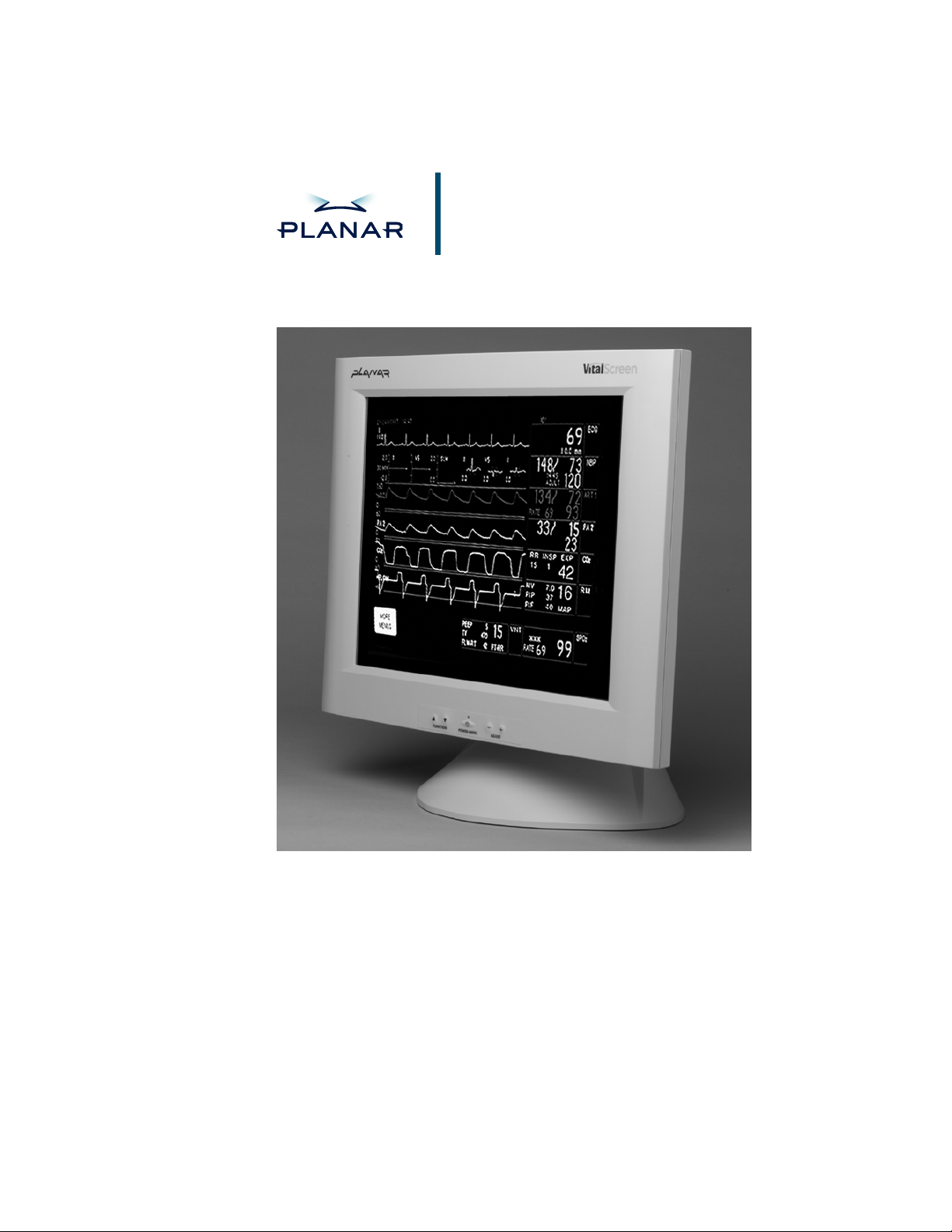
VitalScreen 17.4" Display
VS17.4SXAD / CM17.4SXAD
OPERATIONS MANUAL
www.planar.com
Page 2
Planar Systems, Inc. © 2003. All rights reserved.
Information in this document has been carefully checked for accuracy; however,
no guarantee is given to the correctness of the contents. This document is subject
to change without notice. Planar provides this information as reference only.
Reference to other vendors’ product does not impl y any recommendati o n or
endorsement.
This document contains pro p rietary informa tion protected by copyright. No part of
this manual may be reproduced by any mechanical, electronic, or other means, in
any form, without prior written permission of the manufacturer.
Planar and VitalScreen are re gistered trademar ks of Planar Systems, Inc.
DOCUMENT HISTORY
DATE DESCRIPTION
April 2002 020-0168-00A
January 2003 020-0168-00B
Page 3

Regulatory Compliance
VitalScreen CSR
This display has been tested and found to comply with IEC/EN 606 01 - 1
and IEC/EN 60601-1-2 standards, and is certified to meet medical
standard C22.2 No. 601.1-M1990 (C US Mark).
The medical display, in addition to meeting medical requirements,
has been tested and found to comply with the limits for Federal
Communications Commission ( FCC) Class B computing devices in
a typically configured system since many medical offices are located in
residential areas. It is the system integrator’s re sponsibility to test and
ensure that the entire system complies wi th applicable electromagnetic
compatibility (EMC) laws.
Planar Systems, Inc. has made great efforts to support the medical
device industry, in particular, medical device manufacturers and medical
device system integrators. We offer state-of-the-art color displays that are
compliant with worldwide accepted medical device safety standards, and
for the European market, CE-marked displays based on compliance with
counsel directive 93/42/EEC—commonly referred to as the Medical Device
Directive (MDD). The following summarizes our qualification of these
displays as it relates to compliance with the MDD.
iii
The European Medical Device Directive requires that the intended use
of the device be defined. The intended use of these displays is “to display
alphanumeric, graphic, and image data as inputted from any type of
medical device.” These displays do not provide a measurement function
in any way, and it is the device and systems manufactur er’s responsibility
to verify its function in the integrated device or system.
The display was classified as required by the MDD according to Annex IX
of the directive and the medical device (MEDDEV) guidance available
at the time of classification. Because the display uses electrical energy
and has no direct patient connections andby itselfno medical utility,
the display is classified according to Rule 12 as an MDD Class I devicecomponent or ac c e s s o ry. The MDD stat es t h a t m anufa c tu r ers of Cla s s I
medical devices or acces sories shall satisfy the r equirements in regard
to design and manufacturing controls, that is, the applicable assessment
route to be used for CE-marking under the MDD, and it shall carry
the CE mark according to Annex XII of the directive, with no notified
body annotation.
The applicable safety standards for an MDD Class I display are
IEC/EN 60601-1:1900 along with Amendments 1 and 2. To help the
medical device designer evaluate the suitability of these displays,
Planar has also conducted EMC testing to I EC 60601-1-2 a s it can
be applied. The display with its power supply alone does not represent
a functional medical device. Hence, Planar configured a minimal
operating system to exercise the display. The resulting data are
made available to interested parti es.
The data are informative data, not certification data. Certification
data must be o btain ed by the device or system integrator according
to Article 12 of the MDD titled “Particular procedure for systems and
procedure packs.” Paragraph 2 clearly outli nes the device or system
integrator’s respons ibility in this matter.
VS17.4SXAD / CM17.4SXAD
020-0168-00B)
(
Page 4

iv
In summary, Planar Systems, Inc. is CE-marking these di splays
under the Medical Device Directive, which establishes compliance to
the basic medical safety standards. However, EMC compliance can
only be accomplishe d in the configur ed medical devic e or syst em and
is the responsibility of the device or system manufacturer. Planar has
the necessary documentation such as IEC 60601-1 notified body and
other third-party test reports and certifications, a risk/hazard analysis,
an essential requ irements checklist, and the Planar International
Electrotechnical Commission (IEC) declaration of co nformity.
Planar Systems, Inc., located in Beaverton, Oregon, USA, is the
manufacturer of these displays in the meaning of the directive.
As required by the MDD in Article 14, Planar Systems, Inc., not
residing in the European Economic Area (EEA), has a European
representative, Planar Systems, Inc.Espoo, Finland.
In the opinion of Planar Systems, Inc. registration requir e d to put this
device into commerce is the responsibility of the medical device/system
manufacturer, and Planar sup ports this requirement by providin g a
European Commission (EC) declaration of conformity. If Planar supplies
a display to an end user, rather than a device manufacturer, it is the end
user’s responsibility to ensure continued compliance with the MDD of
the system in which the display is integrated.
For vigilance reporting as required under Article 10 of the MDD,
Planar Systems, Inc. will provide any information requested by
competent authority to support any reported incident investigation
by such an authority.
European Union Declaration of Conformity for Medical Applications
A Declaration of Conformity has been filed for this product. For
additional copies of the Declaration of Conformity document, contact
Planar Systems, Inc. and request document number 001-0014- 05
“Declaration of Conformity.”
VitalScreen CR
Manufacturer Dec laration
This certifies that this product is in compliance with the EU Directive
89/336/EEC, using the EMC standards EN55022 (class B), EN50081-1
and EN50082-1. This product meets or exceeds EN60950, UL1950, and
CSA 22.2 No. 950 safety requirements. This product has been tested and
verified to meet CISPR 22 Class B requirements.
VS17.4SXAD / CM17.4SXAD
020-0168-00B)
(
Page 5

FCC Compliance Statement
This equipment has been tested and found to comply with the limits for
a Class B d igit al devi c e , pu rsuan t t o P a rt 15 of the FCC Ru l es. The s e
limits are designed to provide reas onable protection against har mful
interference when the equipment is operated in a residential installation.
This equipment generates, uses, and can radiate radio frequency energy
and, if not installed and used in accordance with the instruction manual,
may cause harmful interference to radio communications. However,
there is no guarantee that interference will not occur in a particular
installation. If this equipment d oes ca use harmful interference to radio or
television reception, which can be determined by turning the equipment
off and on, you are en coura ged to try to co rrect the interference by one or
more of the followi ng measures:
• Reorient or relocate the receiving antenna.
• Increase the separation between the equipment and the receiver.
• Connect the equipment into an outlet different from that to whic h
the receiver is connected.
• Consult the dealer or an experienced radio/TV technician for help.
v
To comply with the limits for an FCC Class B computing device,
always use the shielded signal cord and shielded power cord supplied
with this unit.
The Federal Communications Commission warns that changes or
modifications of the unit not expres sly approved by th e party responsible
for compliance could void the user’s authority to operate the eq uipment.
VS17.4SXAD / CM17.4SXAD
020-0168-00B)
(
Page 6

Page 7

Contents
vii
About This Manual ..............................................................ix
Product Information............................................................ .
x
1 The VitalScreen 17.4" Displa y...........................................1
VitalScreen CSR........ ... .. .. .. .. .. ... .. .. .. .... ... .. .. .. .. ... .. .. .. .. .. ..... .. .. .. .2
VitalScreen CR.................. .. .. .. ... .. .. .. .. ..... .. .. .. .. ... .. .. .. .. .. ..... .. .. .. .
Distinguishing the Displays ...................................................
Selecting a Workspace.............................................................
Unpacking the Display.............. .. .. .. .. .. ..... .. .. .. ... .. .. .. .. ... .. .. .... .. .
Identifying the Components...................................................
2
2
3
3
4
2 Installing the Display........................................................... 7
Safety Precautions......................... ..........................................
Connecting the AC Power to the Display.............................. 7
Connecting the Display to the System............. .. .. .. .. .. ... .. .. .... .
Connecting a Video Device.............. .. .. ... .. .. .... ... .. .. .. .. ... .. .. .... .. .
Connecting the Optional Touch Screen.... .............................
Mounting the Display........................ .. ... .. .. .... ... .. .. .. .. .. ... .. .. .. .. .9
Power Management System ..................................................
7
8
9
9
10
Landscape-to-Portrait Mechanical Conversion....................
10
3 The Display Controls..........................................................11
Using the Onscreen Display ........... .. .. ... .. .... .. ... .. .. .. .. ... .. .. .. ....11
Onscreen Display Main Menu.... .. .. .. .. ... .. .. .. .. ..... .. .. .. ... .. .. .. .. ..
S-Video and Composite Video Settings.............. .. .. ..... .. .. .. .. ..
Onscreen Display Lockout .......... .... .. .. ... .. .. .. .. ... .... .. .. ... .. .. .. .. ..
Supported CVBS and S-Video Modes........ .. .. ... .. .. .. .. ... .. .. .. .. ..
11
15
16
16
Appendix A: Technical Information................................19
Appendix B: Troubleshooting
Index
.......................................................................................21
..........................................
Description of Warranty.....................................................
Ordering Information .......... ................................................
20
23
25
VS17.4SXAD / CM17.4SXAD
020-0168-00B)
(
Page 8

ix
Page 9
About This Manual
Congratulations on your purchase of the Vi talScreen display!
This operations manual will help you set up, use, and maintain
the VS17.4SXAD or CM17 . 4SX AD model prop erl y. Retain this
manual for future reference.
Read this section carefully to learn how to handle the display safely
and clean it correctly. It explains the symbols used on the products
and the conventions used in this manual.
Chapter 1 provides an overview of the VitalScreen display. It lists
the contents of the display package and identif i es th e co mponents of
the display.
Chapter 2 explains how to install the display correctly and use
optional components.
Chapter 3 explains the menus and function controls built into
the display.
Appendix A contains technical information.
Appendix B focuses on troubleshooting.
Warranty description and ordering information are provided at
the back of this manual.
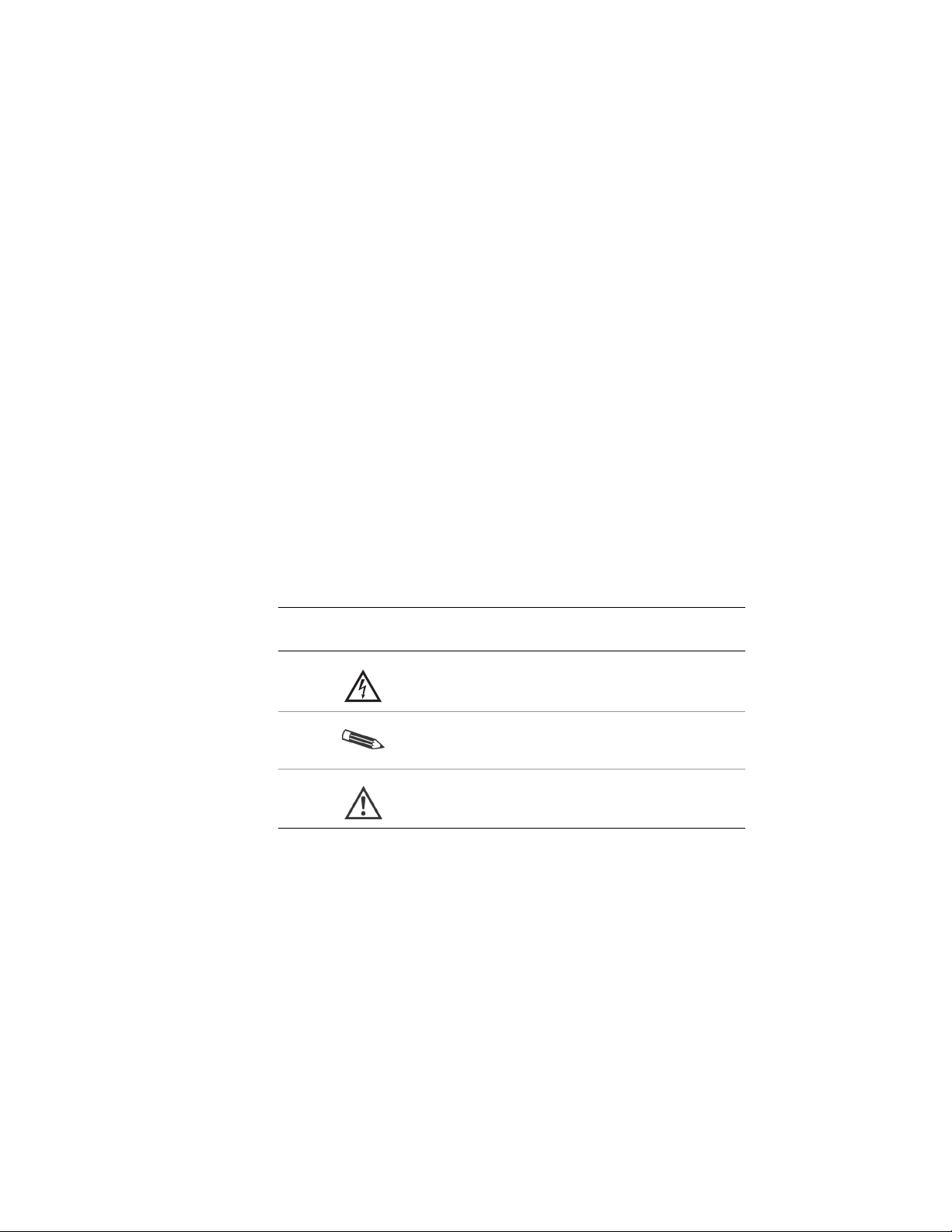
Conventions
The VitalScreen display documentation uses these conventions.
This convention…
Indicates…
A warning that can prevent injury to you,
such as electric shock.
A note of important information regarding
a particular topic or procedure.
A caution that can prevent potential damage
to hardware or software
.
VS17.4SXAD / CM17.4SXAD
020-0168-00B)
(
Page 10

x | Product Information
Product Information
Safety Instructions
Store the display in its original shipping carton when it is not in
operation for extended periods of time. Also use the original packing
materials and carton when shipping the display.
• Do not place the display near a window. Exposing the display to rain,
water, moisture, or constant direct sunlight can damage it.
Do not place anything on top of the display-to-computer signal cord.
•
Make sure the cord is placed where it will not be stepped on.
• Do not apply excessive pressure to the screen. Excessive pressu re
may cau s e permane n t d amage to th e displa y.
• Do not operate the touch screen with sharp object s, such as a scalpel .
Sharp objects can scratch or damage the touch screen. A damaged
touch screen may pose a safety hazard.
• Refer all servicing to qualified personnel to maintain your
warranty. The display and power supply units contain no
user-serviceable parts.
• Do not cover or obstruct the venting holes on the back of
the display.
• Store the display in an environment with a temperature
range from −20 to 65 degrees Celsius (from −4 to 149 degrees
Fahrenheit). Storing your display outside that temperature
range could result in permanent damage.
• Replace any cord or cable th at is frayed or damaged with
another of th e same type and rating as supplied by Planar.
(See “Ordering Information” at the end of this manual for part
numbers.) The safety and regulatory listings and certifications
are based on the cable supplied by Planar.
• Do not expose the display to liquid or drop it. If the case has been
damaged, the unit may pose a shock or fire hazard. Unplug the unit
immediately and c al l customer service for assistance.
• Use only the power adapter that has been test ed and approved
for use with this display product. (See “Ordering Information” for
part numbers.)
The power adapter must be plugged into a grounded power outlet.
• Use a cloth dampened with liquid cleaner to clean the power adapter.
Wipe the outside of the enclosure and c able on ly. Do not immerse the
adapter in liquid, or a safety hazard could arise during use.
• Do not use the pow e r adapter near i nflammable anesthetics.
VS17.4SXAD / CM17.4SXAD
020-0168-00B)
(
Page 11

Product Information | xi
Cleaning Instructions
The VitalScreen display will continue to operate while being cleaned in
a fashion normal for a hospital environment. This means cleaning the
display with a damp, mild soapy cl oth.
The VitalScreen withstands nonabrasive cloths and cl eaning sol utions
used in hospital for like equipment. This cleaning typically includes warm
water and mild detergent for all surfaces or 70 percent isopropyl alcohol
for the touchscreen surface.
Possible cleaning solutions
• 70 percent isopropyl alcohol
• 1.6 percent aqueous ammonia
• Cidex
• Sodium hypochlorite (bleach) 10 percent
• “Green soap” United States Pharmacopoeia (USP)
• 0.5 percent Chlorhexidine in 70 percent isopropyl alcohol
• Ovation
• Formula 409
• Fantastic
•
(2.4 percent glutaraldehyde solution)
WexCide
To clean the screen
Stand away from the display and spray the cleaning solution onto
a clean nonabrasive cloth. Without applying excessive pressure, clean
the screen with the slightly dampened cloth. Dry the screen with
a clean nonabrasive cloth to remove any residue.
Do not spray liquid cleaners directly onto the screen.
Disposal Information
The VitalScreen display contains cold cathode fluorescent lamps, which
contain a maximum of 20 milligrams of mercury (5 milligrams per lamp).
Follow local ordinances or regulations for its disposal.
VS17.4SXAD / CM17.4SXAD
020-0168-00B)
(
Page 12
xii | Product Information
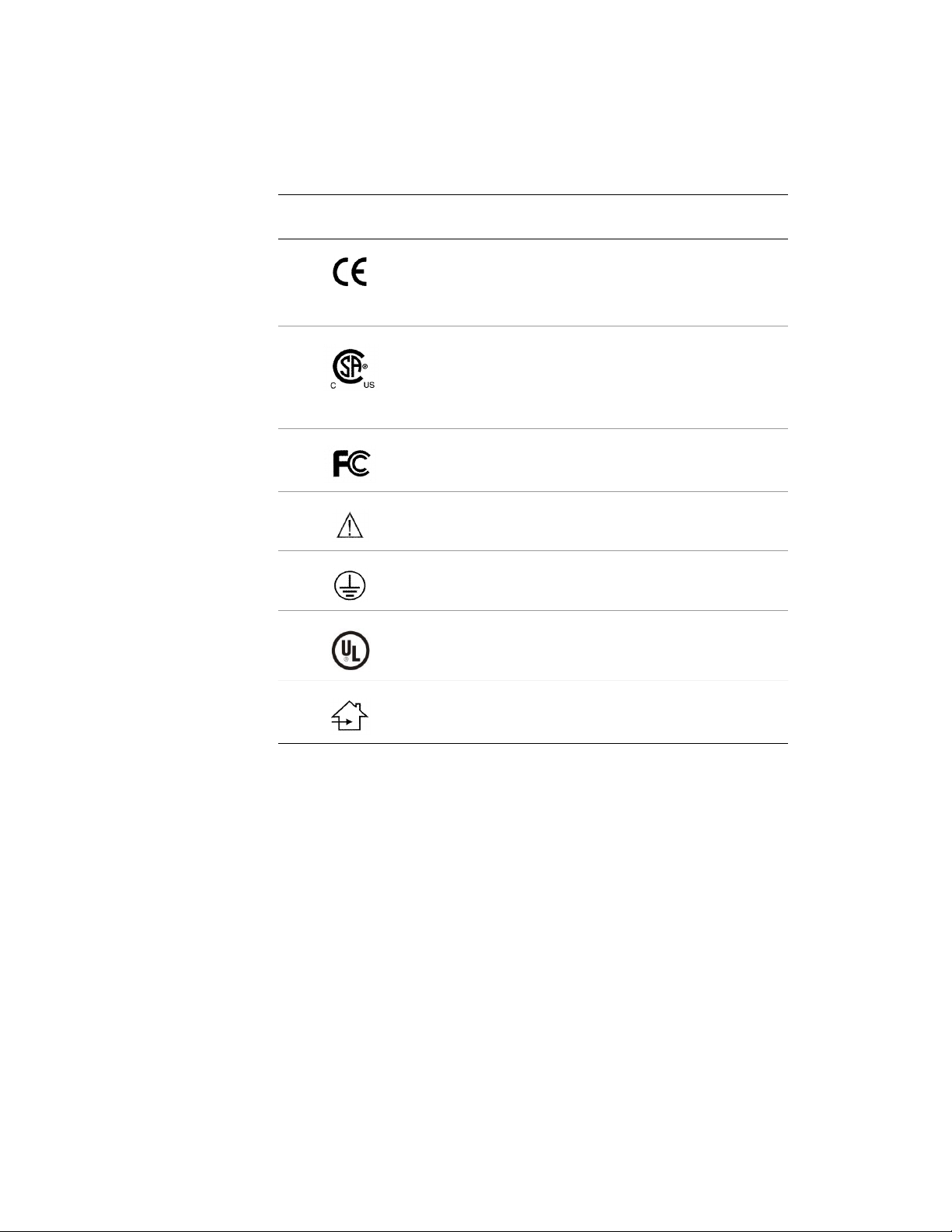
Symbol Explanations
This table explains the symbols appearing on the display or power
supply adapter.
This symbol… Indicates…
Proof of conformity to applicabl e European Economic
Community Council direct i ves and two harmonized
standards published in th e official journal of the
European Communities.
The product has been tested to specific requirements of
medical or ITE device standards. If this mark appears with
the indicators “C” and “US,” the product is certifi ed for the
Canadian and U.S. markets, meeting the appl icable
Canadian and U.S. standards.
The product has been tested to com ply with
FCC Class B standards.
More information availabl e i n a ccompanying documents.
Protective earth ground.
The product has been tested to compl y wit h Underwriters’
Laboratories standards.
Indoor use only.
VS17.4SXAD / CM17.4SXAD
020-0168-00B)
(
Page 13

The VitalScreen 17.4" Display
The architecture of the VitalScreen CSR and VitalScreen CR display s
incorporate an active matrix liquid-crystal display (AMLCD) panel that
produces a bright, high-contrast image with low radiation emission.
This technology greatly reduces the radiation-related health concerns
associ ated with cathode-ray tube (CRT) monitors.
Each VitalScreen is a high-resolution color display designed to be
versatile and easy to use. The display accepts either analog or digital
video (DVI) input and displays most video standards from 640 x 480
(VGA standard) to 1280 x 102 4 (SXGA standard). The controls located
on the front panel allow you to easily adjust the display parameters
using onscreen display (OSD) menus.
The digital video input is a singl e -link, transition minimized differential
signaling (TMDS) digital visual interface (DVI), and is in compliance
with the Digital Display Working Group (DDWG) DVI standard. This
interface produces the sharpest display image possible with little need
for adjustment. The setup is Plug and Play.
Each display has a built-in mounting platform that conforms to the
Video Elec tronics Standards Associatio n (VESA) mounting sta ndar d.
1
This configuration allows the display to be mounted in a variety of
ways, such as on a wall bracket or articulated swing arm. An a lternate
configuration with a desk stand is also available for easy use on flat
work surfaces.
Both displays have features making them ideal for hospital applications.
The housing is an acrylic cover that protects the display from bumps,
falls, collisions, and even everyday cleaning. In addition, Planar offers
configuration management to ensure that you receive a consistent and
predictable product.
The Planar 17.4" display series, for the first time, consists of these two
dist inct v er s ions: Vita lScre e n C SR and Vital S creen CR. B o th disp l ays
have been designed for hospital use, but they have several differences.
VS17.4SXAD / CM17.4SXAD
1
The VESA Flat Panel Monitor Physical Mounting Interface (FPMPMI)
Standard defines physical mounting in terfaces for flat-panel displays,
corresponding standard s (75 and 100 millimeters) for flat-panel disp lay
mounting devices, and associated cable, cable connectors, and power supply
location guidelines. For more information, refer to www.vesa.org.
020-0168-00B)
(
Page 14

2 | The VitalScreen 17.4" Display
VitalScreen CSR
This display has been designed, tested, and certified for use within
the patient vicinity. It has lower electric discharge, thus reducing
the likelihood of electric shock. The display is certified to UL-2601,
IEC 60601-1, an d other representatives of the most stringent electric
discharge certifications available. In addition, the interface buttons on
the front panel are sealed by a plastic membran e , allowing simpler and
safer cleaning. The display also meets the liquid/particle ingress
certifications, IPX-1.
VitalScreen CR
This display has been designed for hospital use outside the patient
vicinity. It is not certified UL-2601 or IEC 60601-1. In addition, the
interface buttons are not sealed on the front panel, and the display
does not meet IPX-1 standards.
The VitalScreen CR display has been tested and found to comply with
the limits for a Class B digital device pursuant to Part 15 of FCC rules.
The interface buttons on the VitalScreen CR display are not sealed
and can be harmed if exposed to liquids. Use caution when cleaning
near the front panel.
Distinguishing the Displa ys
Many of the features and benefits that differentiate the VitalScr een CSR
and VitalScreen CR displ ays are not visually apparent. The simplest way
to identify your Pl anar display is to check the interface buttons on the
front panel.
Note these differences for the interface buttons:
• Interface buttons on the front panel of the VitalSc reen CSR display
(left) are sealed by a plastic membrane.
• Interface buttons on the front panel of the VitalScreen CR display
(right) are not sealed.
The display on the cover of this manual is a VitalScreen CSR. A plastic
membrane seals the interface buttons.
VS17.4SXAD / CM17.4SXAD
020-0168-00B)
(
Page 15

The VitalScreen 17.4" Display | 3
Selecting a Workspace
Before unpacking the display, prepare a suitable workspace. You need
a stable and leve l surface near a g rounded wall outlet in an area that
is relatively free of glare from sunlight or other sources of bright light.
The display is cooled by natural convection. For best performance,
do not block the cooling vents.
Unpacking the Display
While unpacking the display, inspect it and other package contents for
shipping dam age that could cause a fire or shock hazard. Immedi ately
report any shipping damage to the carrier or transport company, and
contact customer service for assistance. Keep all packing material in
case you need to ship, store, or return the display.
After you unpack the display, make sure you have these items:
• LCD screen
• AC power supply with 1.5-meter (5-foot) cable
• Power cord for the display, which connects from the AC main supply
to the AC adapter
• 3-meter (9-foot) S-Video/Composite Video cable (if you purchased the
VitalScreen CSR with S-Video and Composite Video support)
• 3-meter (9-foot) audio cable (if you purchased the VitalScreen CSR
with S-Video and Composite Video support)
• 75 and 100 millimeter VESA plates (if you purchased
the VitalScreen CSR without a desk stand)
• 2-meter (6-foot) RS-232 serial cable (if you purchased
the VitalScreen CSR with touchscreen interface)
• 2-meter (6-foot) analog video cable (VGA-VGA) with audio
• 2-meter (6-foot) digital video cable (DVI-DVI) with audio
• Documentation package including CD, operations manual in English,
and EU Declaration of Conformity
If you have questions about what comes with your display, compare the
part number for the display with the ordering information on page 25.
VS17.4SXAD / CM17.4SXAD
020-0168-00B)
(
Page 16

4 | The VitalScreen 17.4" Display
Identifying the Components
The VitalSc r een CSR an d VitalS c reen CR displ ay s p r ovide ea sy access to
all controls and peripheral ports. The following illustrations of the screen
and the front and back panels identify the display controls and ports.
17.4" LCD screen
LCD screen A 17.4-inch diagonal AMLCD. The scr een supports
most display standards fr om 640 x 480 VGA to
1280 x 1024 SXGA.
VS17.4SXAD / CM17.4SXAD
020-0168-00B)
(
Page 17

The VitalScreen 17.4" Display | 5
Front panel
Power switch /
Onscreen display
Function buttons
Adjustment buttons Controls to adjust the selected setting.
Power ON indicator Light-emitting diode (LED) indicator that
Dual function button to control dis play
power and access the OSD menu. Press
this button for 2 seconds to turn the display
ON or OFF. When the display is ON, press
this button once to access the OSD menu.
UP and DOWN arrows to navigate the
OSD menus. When the OSD menu
displays, press these buttons to select
a control function.
The MINUS control decreases the selected
setting. The PLUS control increases the
selected setting. Press either button to
select a menu.
illuminates when the display is ON and
receiving a proper video signal. The
LED blinks when the display is in powersaving mode.
VS17.4SXAD / CM17.4SXAD
020-0168-00B)
(
Page 18

6 | The VitalScreen 17.4" Display
Back panel
Locking 4-pin power connector Connect the low-voltage cable from
USB downstream ports (2) Connect peripherals (e.g., keyboard,
USB upstream port (1) Connect the USB ca ble from the
Audio input jack Connect the system audio lineout
Touchscreen (DB-9 serial) port Connect the system touchscreen cable
Analog (VGA) video input [port 1] Connect the system VGA cable from
Digital (DVI) video input [port 2] Connect the system DVI cable from
2
Connect USB upstream port to computer to use peripherals.
3
For a VitalScreen supporting S-Video and Composite Video, the
S-Video/Composite Video connector replaces the USB ports.
4
Do not use audio from the display speakers as the exclusive audio source in
medical applications, especially not as an alarm indicator.
the power adapter to this port.
mouse) to these ports, if desired.
computer to this port, if desir ed.
to this port to listen to the system audio
on the display stereo speakers .
2
3
4
to this port on a resistive touchscreen
display.
the computer VGA output to this port
for analog mode.
the computer DVI output to this port
for digital mode.
VS17.4SXAD / CM17.4SXAD
020-0168-00B)
(
Page 19

Installing the Display
To install the VitalScreen CSR or Vital Screen CR display, first connect
the power supply unit. Next, connect the video cable. Then choose
whether to connect optional stereo speakers and touch screen.
Safety Precautions
Follow these safety precautions when connecting the displ ay.
• Plug the power ad apter into a grounded power outlet.
• Use a surge protector between the AC adapter and the electrical wall
outlet to prevent sudden current variations from reaching the display.
Connecting the AC Power to the Display
1 Plug the receptacle end of the AC power cord into the
AC power adapter.
2 Plug the power connector of the adapter in to the p ower po rt on
the display. (Locate the locking 4-pin power connector on the
back panel next to the U SB downstream port.)
3 Insert the power cord into a grounded wall outlet.
VS17.4SXAD / CM17.4SXAD
020-0168-00B) 7
(
Page 20

8 | Installing the Display
Connecting the Display to the System
1 Turn off power to the computer, camera, or other output source, and to
the display.
2
Connect the appropriate video cable from the display to the video port
on the output source.
3 Make sure the video cable connector is securely connected to the video
port on the output device.
4
Turn on the display first, then turn on the output device.
5 Set the output device to a supported resolution, if applicable.
(See “Supported CVBS and S-Video Modes” on page 16.)
6 If VGA analog is used, select the Auto-Adjust menu on the onscreen
display, if you are using VGA analog. (See “Onscreen Display Main
Menu” on page 11.) Press the PLUS or MINUS (
activate it.
/ ) control to
VS17.4SXAD / CM17.4SXAD
020-0168-00B)
(
Page 21

Installing the Display | 9
Connecting a Video Device
Use the following instructions if you are hooking up a camera, VCR, or
other S-Video or Composite Video device, and n ot using the VGA or DVI
input simultaneously. Th ese instructions apply to S-Video and Composite
Video input-equipped displays only.
1
Press the Power/Menu button until the Power ON indicator blinks.
After a moment, a No Sig n al Comi n g mes sag e appe ar s.
2 Wait for the No Signal Coming message to disappea r, approximately
3 to 5 seconds.
3
Press the Power/Menu button to displ ay the VGA → VIDEO menu.
4
Press the PLUS or MINUS (
5 Press the UP (
an alternate video source.
6 Press the PLUS or MINUS (
video mode.
) arrow t o change video modes if you are using
/ ) control to enter video mode.
/ ) control to select the desired
Connecting the Optional Touch Screen
If your VitalScreen CSR or VitalScreen CR display has the optional touch
screen, connect the display 9-pin D-sub serial port to the computer 9-pin
RS-232 serial port using the cable supplied with the touchscreen package.
Next, connect the RS-232 cab le to the 9-pin serial port on the back panel
of the display.
Do not operate the touch screen with sharp objects, such as a scalpel.
Sharp objects can scratch or damage the touch screen. A damaged touch
screen may pose a safety hazard.
Mounting the Display
When mounting y o ur display, such as to a wall br acket or an
articulated swing arm, make sure the maximum length of the
screws inserted into the display mounts is 9 millimeters. Forcing
the screws deeper into the mounts and exceeding this maximum
length may da mage the display.
VS17.4SXAD / CM17.4SXAD
020-0168-00B)
(
Page 22

10 | Installing the Display
Power Management System
The VitalScreen CSR and VitalScreen CR displays comply with the
VESA Display Power Management Signaling (DPMS) standard. This
standard provides four power-saving modes, based on the display
detecting the horizontal or vertical sync sig nals. This table describ e s
the four modes.
Mode AC Input Power1 LED Status
On 60 watts maximum Steady green
Standby 5 watts maximum Blinking green
Suspend 5 watts maximum Blinking gre en
Off 5 watts maximum Off
1
Including AC adapter
When the display is in power-saving mode or detects incorrect timing,
the screen is blank and the powe r LED indicator blinks.
Landscape-to-Por trait Mechanical Conver si on
The 17.4" display (deskstand version) has a unique feature that allows
a mechanical conversion of the display from the traditional landscape
mode to a vertical portrait mode.
Use both hands whenever you are changing the orientat i on of
the display.
1 Gently pull the lower half of the display toward you.
You must tilt the display upward before rotating it.
2
Rotate the display 90 degr ees to left (counterclockwise) unti l it stops
in portrait mode.
3 Select, if necessary and/or avai lable, the different option on the video
card, or display settings on the control panel.
4 Refer to www.portrait.com
landscape to portrait mode.
for software that allows conversion from
VS17.4SXAD / CM17.4SXAD
020-0168-00B)
(
Page 23

The Display Controls
Read this chapter carefully to use your VitalScreen CSR or
VitalScreen CR display efficiently and effectively.
Using the Onscreen Display
The onscreen display (OSD) makes adjusting the display settin gs
quick and easy. Use the OSD to adjust the brightness, contrast, volume,
position, and language for the options in the display. You can access the
OSD whenever both the computer and display are on. If the computer is
off or in power-saving mode, the OSD is inaccessible.
Onscreen Display Main Menu
Call up the OSD Main Menu by momentarily pressing the Power/Menu
button. Use the Function buttons (UP and DOWN arrows) to scroll
through the menu items. When the desired submenu displays, use
either Adjustment button (PLU S or MINUS control) to select the
submenu. Then use the Function buttons to select the desired
function and the Adjustment buttons to make the needed chang es.
The available control functions are grouped into categories. The
selected mode of operation (either analog or digital) determines
the availabl e categor i es.
VS17.4SXAD / CM17.4SXAD
020-0168-00B) 11
(
Page 24

12 | Installing the Display
Main menu
The following table describes the main menus of the onscreen display.
The Main Menus
Basic setting Change brightness, contrast
Position Change the display attributes
Auto-adjust Auto-adjust the display parameters to optimum
Color temperature Adjust the color settings
Miscellaneous Audio volume, OSD H-position, OSD V-positi on,
Video Switch to video input port. (Avail able with
Language Support six different langua ges: English, Dutch,
Input port Port 1 analog, Port 2 digital
Reset Reset display
Exit Close the onscreen display
values (not available for digital mode)
display mode, FW (firmware) version
S-Video and Composite Video dis play)
German, French, Spanish, Italian
VS17.4SXAD / CM17.4SXAD
020-0168-00B)
(
Page 25

Installing the Display | 13
Function menus
The following tables describe the function menus of the onscreen display.
Basic Setting (Available in analog and/or digital mode)
Contrast Adjust the contrast level of the display Analog
Brightness Adjust t he bri ghtness of the display’s
Video level Auto adjusts video level when selected Analog
Gamma Gamma curve adjustment, ranging from
Frame Sets border color when native size is
To main menu
backlight
0.85 to 1.15
selected and selected resolution is
less than default (1280 x 1024)
Exit
Digital
Analog
Digital
Analog
Analog
Position Menu (Analog mode only)
Clock Adjus t the display pixel alignment
Phase Adjust the screen display for focus and clarity
Default size Appears at display resolution
Native size Displays at computer reso l ution
H-position Horizontal position adjustment (not available for digital mode)
V-position Vertical position adjustment (not available for digital mode)
H-size Horizontal size adjustm e nt
V-size Vertical size adjustment
Graphic/Text Select eit her Graph or Text expansion m ethod (Only
To main menu
available in 720 x 400 and 640 x 480 resolutions)
VS17.4SXAD / CM17.4SXAD
020-0168-00B)
(
Page 26

14 | Installing the Display
Color Temperature (Analog mode only)
1
Color 9300 Set the color temperature of white to
Color 6500 Set the color temperature of white to
Color user Enable "User Color" selection, and
R Adjust red contrast
G Adjust green contrast
B Adjust bl ue contrast
To main menu
1
Three sets of color temperature settings are available: two for standard
settings and one for user adjustment.
9300 degrees Kelvin
6500 degrees Kelvin
adjust individual RGB levels
Miscellaneous Menu
Audio volume Audio volume adjustment
OSD H-position Adjust the OSD position horizontally
OSD V-position Adjust the OSD position vertically
Display mode Shows the display mode
F/W version Shows the firmware version
To main menu
Exit
Quick adjustment functions: Analog and digital modes
For this function… Push this key…
Contrast
Brightness
Audio volume Adjust PLUS ( )
Port selection Adjust MINUS ( )
Function UP (
Function DOWN (
)
)
VS17.4SXAD / CM17.4SXAD
020-0168-00B)
(
Page 27

Installing the Display | 15
S-Video and Compos i te Vid eo S ettings
These functions are active on th e VitalScreen onscreen display when
the display is in S-Video or Composite Video mode.
This option is available only on the VitalScreen 17.4" CSR d isplay.
Settings
The settings are selected wi th the Func tion buttons. Select the UP (
DOWN (
) arrow.
Change the settings with the Adjustment buttons. Select the PLUS (
MINUS (
) control.
Contrast Adjust the contrast le vel of the display
Brightness Adjust the brightness of the display’s backlight
Volume Adjust audio volume
Input Switch between S-Video and Composite Video modes
) or
) or
Video → VGA
Hue Adjust the hue level of the display
Sampling Change Sampling mode settings
Overscan Turn Oversc an ON or OFF
Reset Reset display S-Video or Composite Video settings
Switch between video and VGA/DVI i nputs
Quick adjustment functions
For this function… Push this key…
Input Adjust MINUS ( ) twice
Audio volume Adjust PLUS ( )
Video → VGA
1
Pressing and holding the Power/Menu button for more than 2 seconds turns off
the display.
Power/Menu key,
Adjust MINUS (
1
then push Adjust PLUS ( ) or
)
VS17.4SXAD / CM17.4SXAD
020-0168-00B)
(
Page 28

16 | Installing the Display
Onscreen Display Lockou t
Both di splays incorporate an OSD lockout function that you toggle
active or inactive. Pressing three controls — Function DOWN (
Adjust PLUS (
the OSD from being enabled by the power control. Attempts to enable
the OSD result in an “OSD locked” message onl y. To unlock the OSD,
press the same three controls in the same manner.
Supported CVBS and S-Video Modes
Supported video formats on VitalScreen displays with S-Video and
Composite Video functionality include the following:
PAL B, G, H, I, D
NTSC M, Japan
This option is available only on the VitalScreen 17.4" CSR d isplay.
In the table on page 17, ‘A’ signifies analog mode and ‘D’ signifies digital
mode. Also, if the i nput timing is close to one of the modes, generally
it can be displayed by manually adjusting the clock and/or phase from
within the OSD menu.
),
), and Adjust MINUS ( ) — simultaneously locks out
VS17.4SXAD / CM17.4SXAD
020-0168-00B)
(
Page 29

Installing the Display | 17
Supported Video Modes
Item
Standard
Resolution
Dot Clock
(MHz)
Vertical
Scanning
Frequency
(Hz)
Horizontal
Scanning
Frequency
(kHz)
Sync
Polarity or
Composite
Sync (H/V)
Operating
Mode
1 NEC PC98 640x400 25.20 70.15 31.50 -/- A/D
2 NEC PC98 640X400 21.05 56.42 24.83 -/- A
MAC 13" mode
3
MAC 16" mode
4
MAC 17" mode
5
640x480 30.24 66.67 35.00 -/- A/D
832x624 57.28 74.55 49.73 -/- A/D
1024x768 80.00 75.02 60.24 -/- A/D
6 VGA 640x350 25.18 70.09 31.47 +/- A/D
7 VESA 640x350 31.50 85.08 37.86 +/- A/D
8 VGA 640x400 25.18 70.09 31.47 -/+ A/D
9 VESA 640x400 31.50 85.08 37.86 -/+ A/D
10 VGA 640x480 25.18 59.94 31.47 -/- A/D
11 VESA 640x480 31.50 72.81 37.86 -/- A/D
12 VESA 640x480 31.50 75.00 37.50 -/- A/D
13 VESA 640x480 36.00 85.01 43.27 -/- A/D
14 VESA 800x600 36.00 56.25 35.16 +/+ A/D
15 SVGA 800x600 40.00 60.32 37.88 +/+ A/D
16 VESA 800x600 50.00 72.19 48.08 +/+ A/D
17 VESA 800x600 49.50 75.00 46.88 +/+ A/D
18 VESA 800x600 56.25 85.06 53.67 +/+ A/D
19 VGA 720x400 28.32 70.09 31.47 -/+ A/D
20 VESA 720x400 35.50 85.04 37.93 -/+ A/D
21 MEDICAL 1024x512 46.76 60.00 34.38 -/- A/D
22 XGA 1024x768 65.00 60.00 48.36 -/- A/D
23 VESA 1024x768 75.00 70.07 56.48 -/- A/D
24 VESA 1024x768 78.75 75.03 60.02 +/+ A/D
25 1024x768 71.64 66.13 53.96 +/+ A/D
26 VESA 1024x768 94.50 85.00 68.68 +/+ A/D
27 VESA 1152x864 108.00 75.00 67.50 +/+ A/D
28 VESA 1152x864 121.50 85.00 77.09 +/+ A/D
29 VESA 1280x960 108.00 60.00 60.00 +/+ A/D
30 VESA 1280x1024 108.00 60.02 63.98 +/+ A/D
31 VESA 1280x1024 127.00 69.85 74.88 +/+ A
32 VESA 1280x1024 135.00 75.03 79.98 +/+ A
33 SUN 1024x768 64.13 59.98 48.29 H+V A
34 SUN 1024x768 74.25 70.04 56.59 H+V A
35 SUN 1024x768 84.38 77.07 62.04 H+V A
36 SUN 1024x800 81.00 72.87 60.99 H+V A
37 SUN 1024x800 94.50 85.53 71.59 H+V A
38 SUN 1152x900 94.50 66.00 61.84 H+V A
39 SUN 1152x900 108.00 76.64 71.81 H+V A
40 SUN 1280x1024 117.00 67.19 71.69 H+V A
41 SUN 1280x1024 135.00 76.10 81.13 H+V A
VS17.4SXAD / CM17.4SXAD
020-0168-00B)
(
Page 30

Page 31

Technical Information
VitalScreen 17.4" CSR/CR Specification
Display panel 17.4-inch (442-mm) SXG A acti ve ma trix LCD
Display colors Full color supporting 8-bits/color
Dimensions (W x H x D)
Weight 20 l b ( 9 kg)
Display area (W x H) 13.6" x 10.9" (345.6 mm x 276.48 mm)
Response time 25 milliseconds Wht>Blk @ 25 milliseconds max.
Viewing angle 160 degrees (ho ri zon ta l or vertical)
Contrast ratio 400:1 in dark room (0 lux) typical
Brightness
Pixel pitch (W x H) 0.297 mm x 0.297 mm
Reliability
Landscape mode
Portrait mode
Non-touch
Resistive touch
Monitor
Backlight
18" x 18" x 8. 5" (457 mm x 4 57 m m x 216 mm)
15" x 19.5" x 8.5" (381 m m x 495 mm x 216 mm)
2
200 cd/m
176 cd/m
30,000 hours mean time between failure (MTBF)
50,000 hours to reach 50% of initial brightness
typica l
2
typica l
Scanning frequen cy
Power consumption
Power supply 12 volts / 5 amps, 60 watts
Audio
Temperature
Humidity
Altitude
Analog
Digital
Operating
Nonoperating
Operating
Nonoperating
Operating
Nonoperating
Horizontal 24 to 81 kHz
Vertical 56 to 85 Hz
Horizontal 38 .6 to 60 kHz
Vertical 50 to 75 Hz
60 w atts maximum
<5 watts in standby or off mode
Stereo speakers with in tegral amp.
(min. 1W/channel, <1% distortion)
0 to 40 degrees Celsius
-20 to 60 degrees Ce lsius
10 to 90 percent relative humidity (non condens ing)
10 to 90 percent relative humidi ty (non condens ing)
0 to 8000 ft (2400 m)
0 to 40,000 ft (12,200 m)
VS17.4SXAD / CM17.4SXAD
020-0168-00B
(
)
19
Page 32

Troubleshooting
PROBLEM: Display is unclear and unstable
This p rocedure is for users of an alog VGA.
This LCD device comes pre-adjusted with standard VGA timing. Due to
output differenc es amon g various VGA cards, you may i nitia lly experien ce
an unclear and unstable display when a new display mode or new VGA
card is detected. To correct the problem, follow these steps:
1 Apply the Auto-Adjust option in the OSD menu for the display to
adjust automatically to the video signal.
2 If the picture remains unstable, consider manual adjustment of the
clock and phase (in the OSD menu of the display). These adjustments
are not recommended for nontechnical users.
3 If the system still does not function properly, get help from technical
support at your system provid er .
PROBLEM: No image appears on LCD screen
If no image appears on the LCD screen , fol low these steps:
1
Make sure the power indicator on the display is illuminated, all
connections are secure, and the system is running on a supported
video timing mode.
2 If the power LED is not illuminated, make sure the AC power
connector is securely connected. If the AC adapter has an LED,
verify that the LED is illuminated. If it is not, contact your dealer
for assistance.
3 Turn the display off and then turn it back on.
4 Connect your system to another Planar 17.4 display, if one is available.
If the system functions properly with the alternate d isplay but not
with the original display, and the original display’s power LED is
blinking, the output timing of the computer’s video board may be out
of the display’s synchronous range. Change to an al ternate mode
(1280 x 1024, or less), or connect to an al ternate video source and
repeat steps 1 and 2.
5 Ensure that the computer’s video port is enabled (DVI or VGA).
This is a function of the video board in the u ser computer system.
See your system’s video board documentation for instructions on
how to enable the video port.
6 If the system does not function with either display, get hel p from
technical support at your system provider.
20 VS17.4SXAD / CM17.4SXAD
020-0168-00B)
(
Page 33

Index
21
A
adjustment func tions, quick, 14, 15
assistance, t echnical, 24
B
back panel, 6
cleaning instructions, xi
components, identifying, 4
connecting
AC power to display, 7
display to system, 8
optional touch screen, 9
video device, 9
controls, display, 11
conversion, mech ani c al , 10
custo mer su pport, 2 4
CVBS and S-video modes, 16
D
display
components, 4
connecting AC power, 7
connecting to syst em, 8
controls, 11
installing, 7
onscreen lockout, 16
onscreen main menu, 11, 12
description of, 1, 2
spec i fications, 19
troubleshooting, 20
unpacking, 3
using onscreen, 11
disposal information, xi
F
front panel, 5
function menu, 13
functions, quick adjustmen t, 14, 15
I
information
disposal, xi
ordering, 25
technical, 19
installing display, 7
instructions
cleaning, xi
safety, x
L
landscape-to-portrait conversion, 10
LCD screen, 4
lockout , onsc reen di splay, 16
M
main menu, onscreen display, 11, 12
mechanical conversion, landscape to
portrait, 10
menu
function, 13
main, 11, 12
O
onscreen display
function menu, 13
lockout, 16
main menu, 11, 12
using, 11
optional touch screen, connecting, 9
ordering information, 25
P
power management system, 10
product symbols, xii
Q
quick adjustment funct io ns , 14, 15
R
repair service, 23, 24
S
safety instruction s, x
selecting workspace, 3
service, repair, 23, 24
screen, LCD, 4
specifications, display, 19
supported video modes, 16
symbol explanations, xii
T
technical
assistance, 24
information, 19
touch screen (optional), connecting, 9
troubleshooting, 20
U
unpacking display, 3
using onscreen display, 11
V
video
device, connecting, 9
mode s, su pport ed , 16
settings, S-video and composite, 15
W
warranty, 23
workspace, selecting, 3
VS17.4SXAD / CM17.4SXAD
020-0168-00B
(
)
Page 34

Page 35

Description of Warranty
Planar Systems, Inc. (Planar) warrants that the goods sold hereunder
will be free of defects in materials and workmanship, and such goods
will substantially conform to the specifications furnished by Planar,
and to any drawings or specif ications furnis hed to Planar by the Buyer
if approved by Planar. This wa rranty shall be effectiv e only if Planar
receives notice of such defect or nonconformance during the period of
the warranty . Planar’s sole and exclu s ive liability for breach of warranty
shall be, at the company’s option, to repair or replace the Planar
product(s) with refurbished units or provide a credit to Buyer in
the amount of the purchase price.
Commencement and duration of warranty
The warranty period begins on the date of shipment from Planar.
The goods sold hereunder are warranted for a period of 36 months
from date of shipme nt unless ot herwise agr eed to b y Buy er and
Planar. No extension of the warranty will be given during the time
the goods are in the possession of Planar.
Place of repair or replacement
To obtain service under this warranty, Buyer must notify Planar of the
defect before expiration of the warranty period and request a “Return
Material Authorization Number (RMA).” If the configuration has been
modified in any manner, the product must be returned to its original
configurat ion before any warranty service will be per f ormed by Plana r.
No goods are to be returned to Planar without prior authorization.
Buyer will be responsible for packaging and shipping the defective
goods to the appropriate Planar service facility. For North America,
the service facility is located in Beaverton, Oregon; for Europe, the
service facility is located in Espoo, Finland.
23
Limitation of warranty
The foregoing warranty shall not apply to defects resulting from
(a) improper or inadequate maintenance by Buyer; (b) unauthorized
modification of the goods; (c) operations of the goods outside the
environmental specifications of the goods; (d) neglect, misuse, or
abuse of the goods; or (e) modificati on or integra tion with other
goods not covered by the Planar warranty when such modification
or integration increases the likelihood of damage to the goods.
THE WARRANTY IS GIVEN BY Planar IN LIEU OF ANY OTHER
WARRANTIES, EXPRESSED OR IMPLIED. Planar DISCLAIMS ANY
IMPLIED WARRANTIES OF MERCHANTABILITY OR FITNESS
FOR A PARTICULAR PURPOSE. Planar’s RESPONSIBILITY TO
REPAIR OR REPLACE DEFECTIVE PRODUCTS IS THE SOLE
AND EXCLUSIVE REM E DY PRO VID ED TO THE BUY ER FO R
BREACH OF THIS WARRANTY. Planar WILL NOT BE LIABLE
FOR ANY INDIRECT, SPECIAL, I NCIDENTAL, OR CONSEQUENTIAL
DAMAGES IRRESPECTIVE OF WHETHER Planar HAS ADVANCE
NOTICE OF THE POSSIBILITY OF SUCH DAMAGES.
VS17.4SXAD / CM17.4SXAD
020-0168-00B
(
)
Page 36

24
The warranty set forth above shall not be enlarged, diminished, or
affected by, and no obligation or liability shall arise from, Planar, any
authorized dealer, or any other person’s r endering of technical advice,
assistance, or ser vices in connection wit h the Bu yer’s order of the goods
furnished hereunder. The Buyer is not relying on skill or judgment of
Planar to select or furnish suitable goods.
Installation
Planar makes no warranty with respect to any installation of Planar
product(s) by Planar, any au thorized dealer, or any other person.
Technical assistance
In North America, call (503) 748-1100 between 8 A.M. and 5 P.M. Pacific
time, Monday through Friday, or send a description of your technical
issues and e-mail address to tech_support@planar.com.
In Europe, call +358 9 420 01 between 8
A.M. and 4 P.M. Finnish
time (Eastern Eur op ean ti m e), Mond ay th ro ugh Fri d ay, or send
a description of your technical issues and e-mail address to
intltech_support@planar.com.
Repair service
In North America, call Planar at (503) 748-1100 between 8 A.M. and
4
P.M. Pacific time, Monday through Friday, or fax your request to
(503) 748-1493. You will need the unit’s serial number and a brief
description of the problem to receive an RMA number.
In Europe, call Planar Customer Ser vice at +35 8 9 420 01 between 8
and 4
P.M. Eastern European time, Monday through Friday, or fax your
request to +358 9 420 0200. You will need the unit’s serial number and
a brief description of the problem to receive an RMA number.
To protect Planar employees from potential health hazards, Plan ar
requires that the RMA product b e disinfected before returning to
Planar for service. Any product not cleaned prior to shipment will
be returned to the customer.
Returns are not accepted without an assigned RMA number.
In-transit damage is not covered by the warranty. Insure your shipment.
Planar will only pay for the return shipment by surface transportation.
It is the responsibility of the sender to prepay transportation char ges.
A.M.
VS17.4SXAD / CM17.4SXAD
020-0168-00B)
(
Page 37

Ordering Information
VitalScreen CSR Part Number
25
VS17.4SXAD 17.4-inch SXGA VitalScreen Medically Certified
Display (non-touch) wit h desk stand and U.S. power cord
VS17.4SXAD 17.4-inch SXGA VitalScr een Medic ally
Certified Display (non-touch) with desk stand and
European power cord
VS17.4SXAD 17.4-inch SXGA VitalScr een Medic ally
Certified Display (non-touch) with standard mounting
(VESA compatible, 75 mm) and U.S. pow er c ord
VS17.4SXAD 17.4-inch SXGA VitalScr een Medic ally
Certified Display (non-touch) with standard mounting
(VESA compatible, 75 mm) and Europea n power cord
VS17.4SXAD-TR 17.4-inch SXGA VitalScreen Medically
Certified Display (resistive touch) with desk stand and
U.S. power cord
VS17.4SXAD-TR 17.4-inch SXGA VitalScreen Medically
Certified Display (resistive touch) with desk stand and
European power cord
VS17.4SXAD-TR 17.4-inch SXGA VitalScreen Medically
Certified Display (resistive touch) with standard mounting
(VESA compatible, 75 mm) and U.S. pow er c ord
VS17.4SXAD-TR 17.4-inch SXGA VitalScreen Medically
Certified Display (resistive touch) with standard mounting
(VESA compatible, 75 mm) and Europe an power cord
996-0497-00
996-0497-01
996-0497-02
996-0497-03
996-0498-00
996-0498-01
996-0498-02
996-0498-03
VS17.4SXADV SXGA 17.4-inch video-equi pped VitalScreen
Medically Certified Display with desk stand and U.S. power
cord (non-touch)
VS17.4SXADV SXGA 17.4-inch video-equi pped VitalScreen
Medically Certified Display with desk stand and European
power cord (non-touch)
VS17.4SXADV SXGA 17.4-inch video-equi pped VitalScreen
Medically Certified Display with universal VESA mounting
solution and U.S. power cord (non-touch)
VS17.4SXADV SXGA 17.4-inch video-equi pped VitalScreen
Medically Certified Display with universal VESA mounting
solution and European power cord (non-touch)
VS17.4SXADVTR SXGA 17.4-inch video-equipped
VitalScreen Medically Cert ified Display with desk stand and
U.S. power cord (resistive touch)
VS17.4SXADVTR SXGA 17.4-inch video-equipped
VitalScreen Medically Cert ified Display with desk stand and
European power cord (res i stive touch)
VS17.4SXADVTR SXGA 17.4-inch video-equipped
VitalScreen Medically Certi fied Display with universal VESA
mounting solution and U.S. power cord (resistive touch)
VS17.4SXADVTR SXGA 17.4-inch video-equipped
VitalScreen Medically Certi fied Display with universal VESA
mounting solution and European power cord (resistive touch)
996-0533-00
996-0533-01
996-0533-02
996-0533-03
996-0534-00
996-0534-01
996-0534-02
996-0534-03
VS17.4SXAD / CM17.4SXAD
020-0168-00B
(
)
Page 38

26
VitalScreen CR Part Number
CM17.4SXAD 17.4 SXGA VitalScreen CR (non-touch) with
desk stand and U.S. power cord
CM17.4SXAD 17.4 SXGA VitalScreen CR (non-touch) with
desk stand and European power c ord
CM17.4SXAD-TR 17.4 SXGA VitalScreen CR (non-touc h)
with standard mounting (VESA compatible, 75 mm) and
U.S. power cord
CM17.4SXAD-TR 17.4 SXGA VitalScreen CR (non-touc h)
with standard mounting (VESA compatible, 75 mm) and
European power cord
CM17.4SXAD-TR 17.4 SXGA VitalScreen CR (resistive
touch) with desk stand and U.S. power cor d
CM17.4SXAD-TR 17.4 SXGA VitalScreen CR (resistive
touch) with desk stand and Europe an power cord
CM17.4SXAD-TR 17.4 SXGA VitalScreen CR (resistive
touch) with standard mounting (VESA compatible, 75 mm)
and U.S. power cord
CM17.4SXAD-TR 17.4 SXGA VitalScreen CR (resistive
touch) with standard mounting (VESA compatible, 75 mm)
and European power cord
Items Included with All Display Products Part Number
996-0514-00
996-0514-01
996-0514-02
996-0514-03
996-0515-00
996-0515-01
996-0515-02
996-0515-03
Cable, VGA-VGA, 2 m, white, smooth surface (analog)
with audio
Cable, DVI-DVI, 2 m, white, smooth surface with audio 903-0292-00
17.4" VitalScreen CSR and VitalScreen CR
operations manuals (English)
3 m S-Video/CVBS cable (VS17.4SXADV only) 903-0308-00
3 m audio cable (VS17.4SXADV only) 903-0310-00
Available Cables and Accessories Part Number
100-mm VESA mounting plate 501-0415-00
European medical grade power cord, 1.5 m 903-0251-00
U.S. medical grade power cord, 3 m 903-0169-00
Touchscreen cable, 2 m, white, s m ooth surf ace 903-0233-00
12 V medical grade power supply 902-0238-00
Planar desk stand for 17.4" display 501-0380-00
903-0293-00
020-0168-00
VS17.4SXAD / CM17.4SXAD
020-0168-00B)
(
Page 39

Page 40

North and South America Sales Europe and Asia-Pacific Sales
Planar Systems, Inc.
1195 NW Compton Drive
Beaverton, OR 97006-1992
+1 (50 3) 748-1100 phone
+1 (503) 748-1493 fax
sales@planar.com
tech_support@planar.com
Planar Systems, Inc.
Olarinluoma 9, P.O. Box 46
FIN-02201 Espoo, Finland
+358 9 420 01 phone
+358 9 420 0200 fax
intlsales@planar.com
intltech_support@planar.com
 Loading...