

Page 1
Clarity Matrix Fiber Video
Extension User Guide
Page 2

Copyright © 2015 by Planar Systems, Inc. All rights reserved.
Contents of this publication may not be reproduced in any form without permission of Planar
Systems, Inc.
Trademark Credits
Windows™ is a trademark of Microsoft Corp.
All other names are trademarks or registered trademarks of their respective companies.
Disclaimer
The information contained in this document is subject to change without notice. Planar
Systems, Inc. makes no warranty of any kind with regard to this material. While every
precaution has been taken in the preparation of this manual, the Company shall not be liable
for errors or omissions contained herein or for incidental or consequential damages in
connection with the furnishing, performance, or use of this material.
Warranty and Service Plans
Planar warranty and service plans will help you maximize your investment by providing great
support, display uptime, and performance optimization. From post-sale technical support to
a full suite of depot services, our services are performed by trained Planar employees. When
you purchase a Planar product, you get more than a display, you get the service and support
you need to maximize your investment. To find the latest warranty and service information
regarding your Planar product, please visit
http://www.planar.com/support
RoHS Compliance Statement
The Clarity Matrix Video Walls are fully RoHS compliant.
ADA Compliance Statement
The Clarity Matrix Video Walls are compliant with the Americans with Disabilities Act.
Part Number: 020-1300-00A
Page 3

Introduction
The Clarity MatrixTM with G2 Architecture has added to its mission-critical
capabilities with the Fiber Video Extension option. The Clarity Matrix
Extension option provides a more secure and longer distance option for extending
the video signal from the off-board electronics to the Clarity Matrix LCD modules.
Features of the Fiber Video Extension option include:
• Utilizes fiber optic cable to extend the Matrix G2 video signal
• Allows the Quad Controller module and the Fiber Video Extension module to be
placed up to 1000 feet/300 meters away from the Matrix wall with standard
duplex multi-mode fiber cable or up to 10 kilometers with duplex single-mode
fiber cable
• Extends the IR remote control over the fiber cable
• Extends the USB signal for the Matrix MultiTouch sensor and can power the
touch sensor from the Matrix LCD module
Manual Scope
This manual covers the unpacking, installation and troubleshooting of the Fiber
Video Extension option.
TM
Fiber Video
General and technical information regarding fiber optics can be found here:
http://www.thefoa.org.
For specific fiber termination details, please reference the information supplied by
the termination kit and/or fiber cable manufacturer.
© 2015 Planar Clarity Matrix Fiber Video Extension User Guide 3
Page 4
System Architecture
C
The Fiber Video Extension module is the main component of the Fiber Video
Extension option. It works with the Quad Controller module to send images to the
LCD modules.
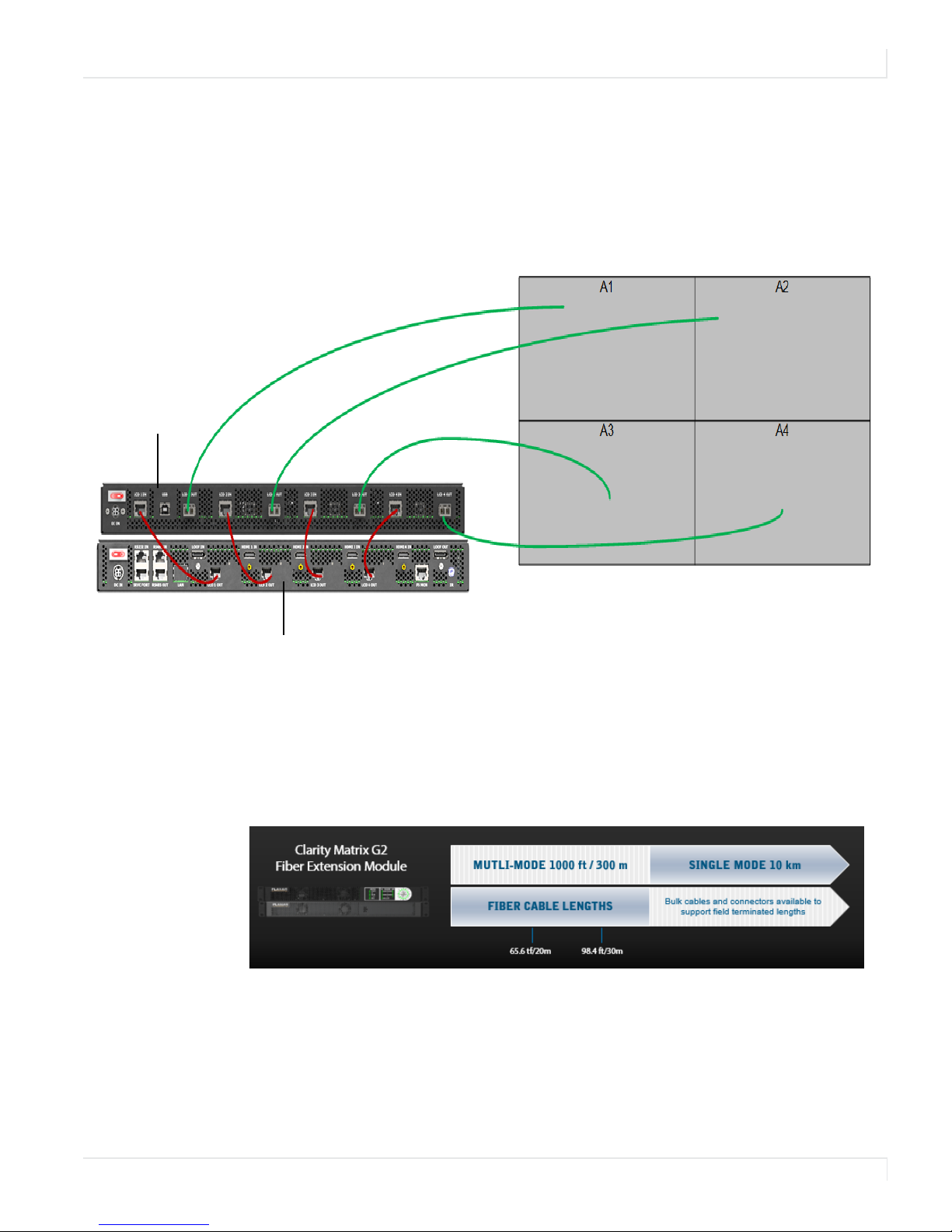
The following example shows the connections for a basic video wall.
larity Matrix Fiber Video
Extension Module
System Architecture
Clarity Matrix Quad Controller
Supported Fiber Cable Lengths
The following graphic illustrates the supported fiber cable lengths for the Fiber Video
Extension module. Planar supplies multi-mode transceivers, but the Fiber Video
Extension module is also compatible with single-mode transceivers available from
third parties.
Note: To accommodate the Fiber Video Extension module extended distance difference from
the maximum Power Supply distance, Quad Controllers may need to be separated from the
Power Supply module and powered from an optional DC Power Brick. See the Clarity Matrix
LCD Video Wall System with G2 Architecture Installation Guide for information.
© 2015 Planar Clarity Matrix Fiber Video Extension User Guide 4
Page 5

Fiber Video Extension Module – Front View
Air intake – keep clear
Fiber Video Extension Module – Rear View
System Architecture
Fiber module
power switch
DC Power (4-pin mini-DIN)
for Fiber module
USB 2.0
(Type-B connector)
SFP fiber transceiver connection output to the panel
Input from the Quad Controller
© 2015 Planar Clarity Matrix Fiber Video Extension User Guide 5
Page 6

Installing the Fiber Video
Extension
Unpacking the Box
The following items are included with the Fiber Video Extension module:
Part Description Number Picture
Fiber Video
Extension
module
Transceiver Connections for the fiber
CAT6 patch
cables (1 m)
DC power brick
(4 ft)
Extends the Quad
Controller with fiber optic
cable out to the LCDs.
optic cable.
Connects the Quad
Controller module to the
Fiber Video Extension
module.
Powers the Fiber Video
Extension module.
Includes AC cable (2.5 m).
1
4
4
1
USB cable (3 m) Connects a PC to the Fiber
Video Extension module
for USB devices located at
the panel, such as a touch
sensor.
© 2015 Planar Clarity Matrix Fiber Video Extension User Guide 6
1
Page 7

Optional Accessories
Part Number Description
159-0055-00 10G OM3 50/125 micron multi-mode duplex Plenum fiber optic
159-0054-00 10G OM3 50/125 micron multi-mode duplex Plenum fiber optic
903-1474-00 Bulk Matrix multi-mode fiber cable – 1640 ft./500m spool.
159-0057-00 50 um multi-mode LC Unicam, OM3 pre-polished fiber connector –
159-0058-00 Connector trigger, narrow pitch. Used to create a duplex connector
541-0139-00 Pre-polished kit for field termination of multi-mode and single-
Unpacking the Box
cable – 20 m / 65.6 ft.
cable – 30 m / 98.4 ft.
1 piece.
using 2 159-0057-00 single connectors.
mode LC, SC and ST® compatible connectors. Includes precision flat
cleaver, 1.25 and 2.50 mm VFL ferrule adapters and all required fiber
preparation, cleaning tools and materials.
175-1068-00 Cable Assy, PWR, AUX, TOUCH. Used to connect the optional touch
sensor to the LCD panel for DC power.
© 2015 Planar Clarity Matrix Fiber Video Extension User Guide 7
Page 8

Connecting Cables
This procedure provides steps for how to connect the Fiber Video Extension module
to the Quad Controller module and the LCDs.
It does not cover how to install the LCDs, Quad Controller modules, and power
supply. For detailed installation instructions, refer to the Clarity Matrix LCD Video Wall
System with G2 Architecture Installation Guide.
1 On the Quad Controller module, plug one end of the CAT 6 video cables into
the LCD Out connections. Plug the other end into the LCD In connections on
the Fiber Video Extension module.
Connecting Cables
2 On the Fiber Video Extension module, do the following:
a Insert the transceivers into the LCD Out connections.
b Remove the black cap from the end of each of the transceivers.
c Plug one end of the fiber optic cables into the transceivers.
© 2015 Planar Clarity Matrix Fiber Video Extension User Guide 8
Page 9

Connecting Cables
3 On the Panel Interface Board of each LCD, do the following:
a Insert a transceiver into the LCD In connection.
b Remove the black cap from the transceiver.
c Plug the other end of the fiber optic cable into the transceiver.
4 Connect the DC power brick to the Fiber Video Extension module and plug
the AC power cord into the power source.
© 2015 Planar Clarity Matrix Fiber Video Extension User Guide 9
Page 10

Connecting the USB Option
The Fiber Video Extension also incorporates an embedded USB extension in the fiber
optic cable, eliminating the need for a third party USB extension when using
Clarity® Matrix™ MultiTouch interactive LCD video wall displays and other USB
devices at the video wall. The LCD modules can also provide power for Clarity Matrix
MultiTouch, eliminating the need for separate AC power connection at the video
wall.
Follow these steps to set up the USB option.
1 Connect the touch sensor USB cable to a LCD Panel Interface Board that is
connected to LCD 1 on the Fiber Video Extension module.
2 Use the power adapter cable to connect all points of power on the touch
sensor to the 5V Aux port on any convenient LCD Panel Interface Board.
Connecting the USB Option
3 Connect the touch control PC to the Fiber Video Extension module that is
connected to the LCD Panel Interface Board in step 1.
© 2015 Planar Clarity Matrix Fiber Video Extension User Guide 10
Page 11

Dimensions
Fiber Video Extension Module
Transceiver
© 2015 Planar Clarity Matrix Fiber Video Extension User Guide 11
Page 12

Specifications
Fiber Video Extension Module Specification
Specification MG2-FC Connector Notes
Dimensions in/lbs mm/kg
Width
Height
Depth
Weight
Power In Mini DIN 24-48V, 5A max
Video Input RJ45
Video Out LC SFP+
USB USB Type B
Environmental Specifications
Specification Maximum Minimum Optimal Notes
Temperature
operating
non-operating
40° C
113° F
85° C
122° F
19" 482.4 mm
1.7" 43.7 mm
20.4" 517.7 mm
13.5 lbs 6.1 kg
10° C
50° F
–20° C
–4° F
20° C
68° F
All performance specifications
are maintained within this
temperature range.
Fan Noise 45dB
Altitude (barometric pressure) 2000m Above sea level, or equivalent
barometric pressure. De-rate
temperature 10° for every 1km
above 1000m.
Humidity
operating 80% R.H. 20% R.H. non-condensing
© 2015 Planar Clarity Matrix Fiber Video Extension User Guide 12
 Loading...