

Page 1

CIU-003
TV SIGNAL ANALYZER
OPERATING MANUAL
Page 2

Revision 1.4 from 12.04.13
Page 3

3
TABLE OF CONTENTS
1.
GENERAL DESCRIPTION AND PRINCIPLE OF OPERATION ..........................................4
1.1. INTRODUCTION...................................................................................................................4
1.2. SAFETY PRECAUTIONS ........................................................................................................4
1.3. FUNCTION ..........................................................................................................................4
1.4. ENVIRONMENTAL CONDITIONS............................................................................................7
1.5. PACKAGE CONTENTS ..........................................................................................................7
1.6. SPECIFICATIONS..................................................................................................................7
1.7. DESIGN AND OPERATION OVERVIEW....................................................................................8
1.7.1. Principle of Operation ................................................................................................8
1.7.2. Block Diagram ...........................................................................................................9
1.7.3. Component Arrangement...........................................................................................10
2. PREPARATION FOR OPERATION .....................................................................................10
3. OPERATION PROCEDURE..................................................................................................11
3.1. CONTROLS AND INDICATORS .............................................................................................11
3.2. PREPARATION FOR MEASUREMENTS ..................................................................................11
3.3. ANALYZER CONFIGURATION BY PC ...................................................................................11
3.3.1. General Information .................................................................................................11
3.3.2. Connection to Configuration Terminal.......................................................................11
3.3.3. Connection to LAN....................................................................................................15
3.3.4. Connection to ViewRSA.............................................................................................15
3.3.5. Viewing Device Information ......................................................................................16
3.3.6. Viewing Test Data.....................................................................................................16
3.4. OPERATING ANALYZER WITH VIEWRSA SOFTWARE...........................................................17
3.4.1. General Information .................................................................................................17
3.4.2. PC Configuration Requirements ................................................................................17
3.4.3. Software Installation.................................................................................................18
3.5. OPERATING ANALYZER VIA SNMP PROTOCOL ...................................................................18
3.5.1. General Information .................................................................................................18
3.5.2. Description of CIU-003 Branch in MIB-2 Tree...........................................................19
3.6. UPDATING FIRMWARE.......................................................................................................19
4. MAINTENANCE....................................................................................................................20
5. TROUBLESHOOTING..........................................................................................................20
6. STORAGE..............................................................................................................................21
7. TRANSPORTATION .............................................................................................................21
8. LABELING.............................................................................................................................21
9. WARRANTY INFORMATION..............................................................................................21
10. APPENDIX.........................................................................................................................23
Page 4

4
1. GENERAL DESCRIPTION AND PRINCIPLE OF OPERATION
1.1. Introduction
This Operating Manual is intended for introducing the design, functions, and basic procedures
related to operation, maintenance and transportation of CIU-003 TV Signal Analyzer (Analyzer).
CIU-003 Analyzer is designed for continuous monitoring of television and broadcasting
distribution network parameters, as well as of separate components of such networks, or other
electronic devices. Using the Analyzer, you can measure the channel level and parameters of TV
signal with analog and digital DVB-C and DVB-T modulation.
Reliability of CIU-003 Analyzer is ensured by regular maintenance procedures. These
procedures and their intervals are described in Section 5.
In this manual the following abbreviations are used:
ADC - Analog-to-Digital Converter
HF - High Frequency
IF - Intermediate Frequency
PC - Personal Computer
CD - Compact Disk
LAN - Local Area Network
BER - Bit Error Rate
DVB-C - Digital Video Broadcasting – Cable
DVB-T - Digital Video Broadcasting – Terrestrial
QPSK - Quadrature Phase Shift Keying
QAM - Quadrature Amplitude Modulation
COFDM - Coded Orthogonal Frequency Division Multiplexing
MER - Modulation Error Ratio
MPEG2 - Motion Pictures Expert Group
SNMP - Simple Network Management Protocol
1.2. Safety Precautions
You should thoroughly inspect the product and carefully read the related documentation to get
acquainted with all the safety markings and instructions before you start to operate the Analyzer.
WARNING Only trained service personnel aware of the hazards involved should
perform repair on the Analyzer.
CAUTION Tuning the Analyzer and replacement of the components that
influence the accuracy of measurements without service personnel is strictly
prohibited because the components used in the Analyzer are purpose-made and
their replacement will result in inaccurate operation of the Analyzer. You must
observe the Analyzer storage and transportation instructions (see Sections 6
and 7) to exclude the possibility of mechanical damage to CIU-003.
1.3. Function
CIU-003 TV Signal Analyzer is intended for measurement of TV channel parameters and
transfer of measurement results to remote PC via LAN.
Page 5

5
The Analyzer performs measurement of the following parameters for analog channels: video
signal level, video to audio ratio, and video carrier to noise ratio within the video channel
bandwidth. For digital TV channels the Analyzer measures actual channel power. For DVB-C TV
signals CIU-003 offers the measurement of the following reception quality parameters: modulation
error ratio MER, bit error ratio BER before and after Reed-Solomon decoder. For DVB-T signals
CIU-003 measures modulation error ratio MER, BER after Viterbi decoder and BER after ReedSolomon decoder. Using the Analyzer, you can check MPEG transport stream for compliance with
ETSI TR101290 standard requirements (priority 1 and 2). Also the Analyzer performs analog
channel audio broadcasting (mono) monitoring
1
.
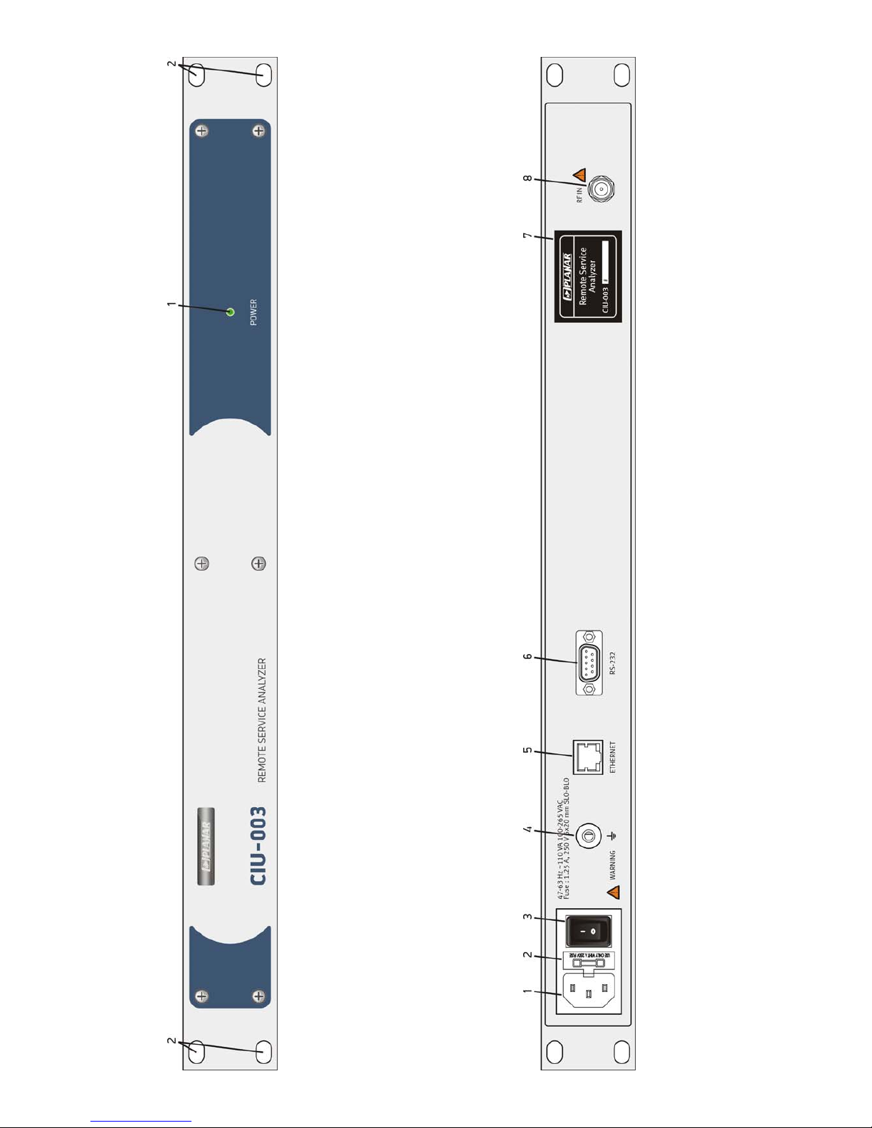
The appearance of the Analyzer and its components is shown in Figures 1.1 and 1.2.
1
For hardware modification 2.14.2 or higher
Page 6
6
Figure 1.1
Figure 1.2
Page 7

This Operating Manual is made in accordance with CIU-003 firmware version 14.0.0.7
and ViewRSA software version 2.1.9.
1.4. Environmental Conditions
Normal operating conditions:
a) ambient temperature 23±5
0
С;
b) relative air humidity 55±25%;
c) atmospheric pressure 84-106 kPa (630-795 mm Hg);
d) voltage transients in compliance with installation category CAT. II.
Rated operating conditions:
а) ambient temperature +10 to +40 °С;
b) relative air humidity not more than 80% at 25 ºС;
c) atmospheric pressure 84-106 kPa (630-795 mm Hg).
1.5. Package Contents
The Analyzer package includes:
a) CIU-003 Analyzer .................................1 pc.
b) Power Supply Cord with Europlug ........1 pc.
c) COM Port Data Transfer Cable ............1 pc.
d) CD with Software ..................................1 pc.
e) Rubber mounts ..................................... 4 pc.
f) Operating Manual ................................. 1 pc.
1.6. Specifications
Input parameters:
a) Input impedance within operating frequency range: 75 Ohm
b) Allowed resulting value of AC input voltage: 2 V
Operating frequency range 48 to 1000 MHz
Resolution 125 kHz
Built-in attenuator 20 dB, 40 dB
Level measurement mode:
- Input attenuator off 30 to 80 dBμV
- 20 dB input attenuator 50 to 100 dBμV
- 40 dB input attenuator 70 to 120 dBμV
Level measurement resolution 0.1 dB
Accuracy within 30-120 dBµV level range ±1.5 dB
Accuracy at operating temperature ±2.2 dB
Measurement channel passband for -3 dB level 230 ± 60 kHz
DVB-C
DVB-C demodulator parameters:
- Supported modulation types QAM64, QAM128,
QAM256
- Supported symbol rate 5000 to 7000 Msps
MER measurement range:
- QAM64 22 to 42 dB
- QAM256 28 to 42 dB
MER measurement resolution 0.1 dB
MER measurement accuracy (DVB-C channel power level no less
than 60 dBμV)
±2.0 dB
BER measurement range:
- BER before Reed-Solomon decoder 5.0x10
-3
to 1.0x10
-9
7
Page 8

- BER after Reed-Solomon decoder 1.0x10⁻⁴ to 1.0x10
-9
DVB-C channel power threshold (preBER <2.0x10
-4
):
- QAM64 45 dBμV
- QAM256 50 dBμV
DVB-C channel automatic frequency control ±0.25 MHz
DVB-T
DVB-T demodulator parameters:
- Modulation type COFDM
- Subcarrier modulation types QPSK, QAM16, QAM64
- Channel bandwidth 7 MHz, 8 MHz
- Number of channel subcarriers 2k, 4k, 8k
- Guard interval 1/32, 1/16, 1/8, 1/4
- Hierarchical modulation α=1, α=2, α=4
- FEC 1/2, 2/3, 3/4, 5/6, 7/8
DVB-T MER measurement range:
- QAM64, FEC 3/4 18 to 35 dB
MER measurement resolution 0.1 dB
MER measurement accuracy within 50 to 110 dBµV level range ±2.0 dB
BER measurement range:
- BER before Viterbi decoder 1.0x10
-2
to 1.0x10
-9
- BER after Viterbi decoder 1.0x10⁻³ to 1.0x10
-9
- BER after Reed-Solomon decoder 1.0x10⁻⁴ to 1.0x10
-9
DVB-T channel power threshold (postVBER <2.0x10
-4
), for
QAM64 , FEC 3/4:
40 dBμV
Automatic frequency control ±0.5 MHz
General parameters
Warm-up time 5 min
Ethernet interface: RJ-45 / 100BASE-TX
LAN parameters IPv4 / DHCP
Control protocols SNMPv1
Non-volatile memory capacity 80 measurement logs 160
channels each
Continuous stable operation under normal conditions Unlimited
Mean time between failures, no less than 10,000 hours
Average lifetime, no less than 5 years
Rack design 19’’/1U (IEC-297)
Dimensions 483x163x44 mm
Package dimensions 560х265х165 mm
Weight 2.0 kg
Weight in package 3.0 kg
CIU-003 is powered from AC circuit with 110-265 V voltage and 47-63 Hz frequency
with no more than 5% harmonic content.
Insert two 5x20 mm fuses with nominal operating current of 1.25 A into the fuse-
holder.
1.7. Design and Operation Overview
1.7.1. Principle of Operation
CIU-003 TV Signal Analyzer is a receiver of DVB-C and DVB-T signals with demodulation to the
MPEG-2 transport stream and its further analysis. The input tuner is a triple superheterodyne
receiver with auto or manual frequency tuning. Modulation error ratio MER is measured in the
process of QAM signal demodulation based on vector analysis. Bit error rate BER in digital stream
is determined by means of analyzing the Reed-Solomon and (or) Viterbi decoder operation.
Channel power is measured using analog-to-digital converter after signal peak detection at output
of logarithmic detector of the third IF amplifier.
8
Page 9
Analog channel audio broadcasting monitoring performs by measuring demodulated sound
signal with an analog-to-digital converter
1
.
The Analyzer is continuously measuring the channel parameters in the selected channel plan
and according to the selected channel template. The results of digital DVB-C/ DVB-T channel
measurement are values of actual channel power level, MER, BER before and after the ReedSolomon/Viterbi decoder. And the results of analog channel measurement are the values of signal
level, video to audio ratio and video carrier to noise ratio within the video channel bandwidth. The
MPEG transport stream is checked for compliance with ETSI TR101290 standard requirements
(priority 1 and 2).
The measured parameters are stored in the non-volatile memory of the Analyzer together with
the time and date of measurement for each channel. The CIU-003 Analyzer can store up to 80
measurement cycles (one cycle includes measurement of all channels in the channel plan). After
the saved measurement results are transferred to a remote PC with installed ViewRSA software,
the corresponding memory cells become available for saving the next measurement results. Thus
all the measurement results can be stored in the ViewRSA database for any period of time.
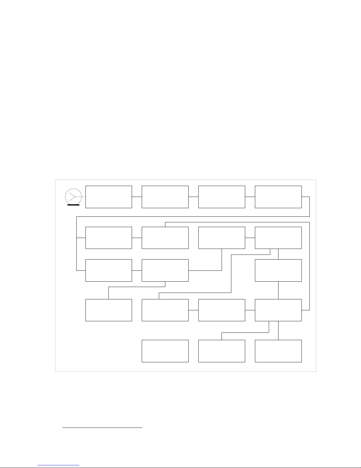
1.7.2. Block Diagram
The block diagram of CIU-003 is shown in Figure 1.3.
Low-Pass Filter
(LPF)
Attenuator
0/20/40dB
(A)
Tuner
(T)
Bandpass Filter
IF2 39.000 MHz
(BPF1)
Mixer
(M)
Bandpass Filter
IF3 10.7 MHz
(BPF3)
Logarithmic Gain
Amplifier Limiter
(LGAL)
Local Oscillator
28.3 MHz
(LO)
Bandpass Filter
IF2 36.125 MHz
(BPF2)
DVB-C/T
demodulator
(DD)
Mains Adapter
(MA)
Control Interfaces
(CI)
Nonvolatile
memory
(NVRAM)
Analog-to-Digital
Converter
(ADC)
Peak Detector
(PD)
Control Unit
(CU)
Wide-Band
Amplifier 0/11dB
(WBA)
Frequency
Detector & ADC
(FD)
Figure 1.3
After passing the Low-Pass Filter (LPF), the input signal, if necessary, is strengthened by the
Wide-Band Amplifier (WBA) or reduced by the Attenuator (A). Then it is transformed by the doubleconversion TV Tuner (T) into the second 39 MHz IF signal in the level measurement mode or into
the second 36.125 MHz IF signal in the DBV-C/DVB-T signal demodulation mode.
9
1
For hardware modification 2.14.2 or higher
Page 10

The second IF signal is converted in the Mixer (M) by means of the 28.3 MHz Local Oscillator
(LO) into the third IF signal, and further filtered by 10.7 MHz filter (BPF3), which also determines
the receiver bandwidth.
Logarithmic Gain Amplifier Limiter (LGAL) performs logarithmation and signal detection.
Peak Detector (PD) enables the measurement of the video carrier level by means of Analogueto-Digital Converter (ADC). The digital code of the input signal peak level logarithm is defined as
real value and corrected in accordance with the calibration matrix of the Control Unit (CU)
microcontroller.
From the LGAL limiter output signal is forwarding to the frequency detector with the built in
analog-to-digital converter, and as a result, demodulated and digitalized signal is processed with
the control unit. This allows to perform analog channel audio brouadcasting monitoring
1
.
In digital DVB-C/DVB-T signal demodulation mode the second IF signal is filtered by the
Bandpass Filter (BPF2) and supplied to the DVB-C/DVB-T Demodulator (DD), which performs
demodulation and measurement of signal parameters. The measured results are processed by the
Control Unit.
The Control Unit (CU) uses the Control Interfaces (CI) to support the Analyzer operation with
ViewRSA software and receive the commands entered by the user during the Analyzer
configuration via COM port.
The nonvolatile memory (NVRAM) stores factory calibration coefficients, channel template,
channel plan, limit plan, measurement logs, and service information.
The Mains Adapter (MA) forms the required voltages from an external power source.
1.7.3. Component Arrangement
CIU-003 TV Signal Analyzer is made in 19’’/1U steel shockproof sectional housing that includes
printed and three-dimensional wiring. The Analyzer dimensions are 483x163x44 mm.
The front panel of the Analyzer (see Figure 1.1) has the POWER indicator (index 1) and holes
for mounting the Analyzer on the rack (index 2). The back panel of the Analyzer (see Figure 1.2)
contains a socket for mains supply (index 1), fuse-holder (index 2), mains switch (index 3),
additional grounding connector
(index 4), ETHERNET RJ-45 connector for the Analyzer
connection to LAN (index 5), RS-232 DB-9 connector for setting and updating the Analyzer
firmware from external PC (index 6), label with the device serial number and type (index 7), and
the RF IN input 75 Ohm F-male connector (index 8).
2. PREPARATION FOR OPERATION
Perform external examination to make sure your CIU-003 is free from any visible mechanical
damage.
Upon receipt of the package, check the availability of the items contained in it against the list
provided (see Section 1.5).
If your CIU-003 has been kept in the environment other than the rated operating conditions,
leave the Analyzer in facilities with normal operating conditions at least for 2 hours prior to
operation.
If the Analyzer is going to be used in laboratory (without mounting into the rack), fix 4 rubber
mounts into the holes of the Analyzer housing base.
10
1
For hardware modification 2.14.2 or higher
Page 11

11
3. OPERATION PROCEDURE
3.1. Controls and Indicators
The location of controls, indicators and connectors is shown in Figures 1.1 and 1.2. These
elements have the following functions:
а) socket for mains supply is intended for the Analyzer connection to power supply line using
the power supply cord;
b) fuse-holder is intended for inserting 2 fuses;
c) mains switch turns the power of the Analyzer on/off;
d) additional grounding connector ensures the Analyzer grounding in case the primary power
supply line does not have a protective grounding loop;
e) POWER indicator shows that the Analyzer is switched on;
f) ETHERNET connector is intended for the Analyzer connection to LAN;
g) RS-232 connector is intended for configuring and updating the Analyzer firmware from an
external PC;
h) RF IN connector is used for the test signal input via F-male connector.
3.2. Preparation for Measurements
Before you start operating your CIU-003, make sure to carefully read this Operating Manual as
well as to inspect the location of the controls and indicators of the Analyzer (see Section 3.1).
To prepare your Analyzer for operation, proceed as follows:
a) make sure that two proper fuses are inserted into the fuse-holder;
b) ground the Analyzer using the additional grounding connector (if the primary power supply
line does not have a protective grounding loop);
c) connect the Analyzer to the 220 V AC circuit via power supply cord;
d) turn the Analyzer on;
e) configure the Analyzer for operation in the LAN by using an external PC (see Section 3.3);
f) connect the Analyzer to the LAN and establish the connection with the ViewRSA software
(see ViewRSA operating manual).
3.3. Analyzer Configuration by PC
3.3.1. General Information
You can use the mode of CIU-003 configuration by PC to perform the following procedures:
a) set and view the following CIU-003 parameters in the LAN: device MAC address, IP address,
subnet mask, and IP address of the network gateway;
b) view the information about your Analyzer: hardware and firmware version, serial number,
current date and time;
c) self-test the Analyzer;
d) set and view ViewRSA connection mode: ViewRSA server IP-address and port.
3.3.2. Connection to Configuration Terminal
The Analyzer setting is performed with Microsoft HyperTerminal or similar software via the
COM port. To configure HyperTerminal software for operation with the Analyzer, proceed as
follows:
a) connect the Analyzer to a free COM port of the PC and turn it on;
b) run HyperTerminal on your PC:
Page 12

START->Programs->Accessories->Communications->HyperTerminal or
START->Run…->type hypertrm command
c) enter the name and select the icon for a new connection (see Figure 3.1);
Figure 3.1
d) select the COM port, which will be used for this connection (see Figure 3.2);
Figure 3.2
e) select the parameters of the COM port as shown in Figure 3.3;
12
Page 13

Figure 3.3
f) after creating a new connection, open the program properties window (on the File menu,
click Properties). Select the Parameters tab and perform the following settings as shown in
Figure 3.4;
Figure 3.4
g) in the same window and tab click the ASCII Parameters… button and set the following
input/output settings as shown in Figure 3.5;
13
Page 14

Figure 3.5
h) after you have finished configuring the settings, press ENTER on the keypad or type help
command or click ? in the input/output window. If the Analyzer is properly connected to your
PC, you will see the text with the list of available commands in the input/output window (see
Figure 3.6).
Figure 3.6
We recommend following the below instructions when entering commands:
a) use ENTER to complete entering of any command;
b) you can use both upper and lowercases for entering symbols;
c) to correct the wrong symbol, change the cursor position by pressing arrow keys;
d) to get additional data about a command, type its name without any additional parameters.
Example:
set
14
Page 15

15
e) if you enter a command incorrectly, unknown command message will appear on the
screen.
3.3.3. Connection to LAN
You should proceed as follows to configure parameters of CIU-003 TV Signal Analyzer in the
LAN:
a) make sure the Analyzer is connected to a free COM port of the PC and that the Analyzer
configuration program is started (see Section 3.3.1);
b) set MAC address of the device (if necessary). Example:
set mac 00:1F:66:03:00:01
CAUTION Each Analyzer has a unique MAC address assigned by the
manufacturer and usually you do not have to change it.
In case the MAC address of the Analyzer was accidentally changed, you can restore its default
value by using the following command:
set mac default
c) if IP addresses in the LAN are appointed by DHCP server, type the following command:
set ip dhcp
CAUTION The IP address appointed by DHCP server shall be static with
unlimited lease time to provide the Analyzer communication with ViewRSA.
In other case, if IP addresses are assigned manually, type the following list of commands (IP
addresses are given only as an example):
set ip 192.168.0.1 - sets the IP address
set mask 255.255.255.0 - sets subnet mask
set gw 192.168.0.101 - sets the IP address of network gateway
d) restart the Analyzer by the following command:
restart
This command is equivalent to switching the Analyzer off and then on again. You should use
this command after changing any of the Analyzer parameters related to its registration in the LAN,
and also after changing the IP address of the Analyzer in DHCP-server table of addresses.
e) connect the Analyzer to the LAN via the ETHERNET connector. If the connection is correct,
orange indicator will flash on the connector;
f) check the Analyzer settings by viewing identification data (see Section 3.3.5);
g) if all the settings of the Analyzer are correct, you can check its communication with the LAN
by pinging its IP address with a remote PC connected to the same LAN.
3.3.4. Connection to ViewRSA
You should proceed as follows to configure ViewRSA and CIU-003 connection mode:
a) make sure the Analyzer is connected to a free COM port of the PC and that the Analyzer
configuration program is started (see Section 3.3.1);
b) If the Analyzer and ViewRSA server are located at the save subnetwork or in the distributed
network without NAT, type the following command:
set server auto
and follow the rule (d)
Page 16

16
c) If the Analyzer and ViewRSA server are operated in the distributed network with NAT you
should set external IP-address and port of the server with the installed ViewRSA software.
IP-address and port of server should be set to be external, taking into consideration that
they will be translated with the NAT. Example of the command (ViewRSA external IP-
address – 10.0.5.101, external port – 48050):
set server 10.0.5.101:48050
d) restart the Analyzer by the following command:
restart
Table of the used TCP/IP ports:
port
connection mode protocol data direction
downstream upstream
TCP CIU-003 ViewRSA 8801 PPP*
set server auto
TCP ViewRSA CIU-003 PPP* 8801
UDP ViewRSA CIU-003 PPP* 8801
TCP CIU-003 ViewRSA 8801 PPP*
set server IP:PPP
TCP ViewRSA CIU-003 PPP* 8801
* PPP – port, set in the ViewRSA settings.
3.3.5. Viewing Device Information
You should perform the following procedures to view information about CIU-003:
a) make sure the Analyzer is connected to a free COM port of the PC and that the Analyzer
configuration program is started (see Section 3.3.1);
b) type the following command:
info
c) the following data will appear in the input/output window:
Device name, e.g.: ***** CIU-003 *****;
Hardware version of the Analyzer, e.g.: HW version: 2.12.1;
Software version of the Analyzer, e.g.: SW version: 12.00.00.04;
Serial number of the Analyzer, e.g.: Serial number: 10040001;
MAC address of the Analyzer, e.g.: MAC address: 00:1f:66:03:00:04;
IP address of the Analyzer, e.g.:
IP address: 192.168.0.1 – if the IP address is set manually;
IP address: assigned by DHCP (not assigned yet) – if the IP address is assigned by
DHCP server, but it has not been assigned yet;
IP address: assigned by DHCP (192.168.0.1) – if the IP address is assigned by DHCP
server, and has already been assigned.
Subnet mask, for example: Subnet mask: 255.255.255.0 (other variants of displaying are
equivalent to those of IP address);
Network gateway address, for example: Gateway: 192.168.0.101 (other variants of displaying
are equivalent to those of IP address);
Date and time (universal), for example: Date/time: 07.06.2010 9:30:00 UTC;
ViewRSA server IP address and port, for example: Server: 10.0.5.101:48050.
3.3.6. Viewing Test Data
You can perform the Analyzer self-test by following the below procedure:
Page 17

17
a) make sure the Analyzer is connected to a free COM port of the PC and that the Analyzer
configuration program is started (see Section 3.3.1);
b) type the following command:
test
c) the following test data will appear in the input/output window:
Device name, e.g.: ***** CIU-003 *****;
Calibration status, e.g.: Calibration: Ok;
Temperature inside the Analyzer, e.g.: Temperature: +37C Ok;
Tuner status, e.g.: Tuner: Ok;
Status of the DVB-C channel demodulator, e.g.: Demod. DVB-C: Ok;
Status of the DVB-T channel demodulator, e.g.: Demod. DVB-T: Ok;
Status of the non-volatile memory, e.g.: Memory: Ok;
Status of the temperature sensor, e.g.: Temp. sensor: Ok;
Clock status, e.g.: Clock: Ok;
Status of the Ethernet module, e.g.: Ethernet: Ok;
Status of the internal data bus, e.g.: Internal Bus: Ok;
Error code, e.g.: Error code: none.
If self-test does not detect any error, Ok status is displayed, and if an error is detected in any of
the test parameters, Error is displayed.
If there is any error detected during self-test, the Analyzer should be sent to repair service to
have the defects corrected.
Temperature error means that the temperature is beyond the allowed range. Temperature error
affects the accuracy of measurements and in some cases may even lead to the Analyzer failure. In
case such error occurs, check the Analyzer operating conditions.
3.4. Operating Analyzer with ViewRSA Software
3.4.1. General Information
ViewRSA software is intended for operating CIU-003 Signal Analyzers via the LAN. With this
software, you can perform the following procedures:
a) edit channel template of the Analyzer;
b) edit channel plan of the Analyzer;
c) edit channel limit plan;
d) view measurement results and save them to the database;
e) check measurement results against limit plans;
f) view device information;
g) view self-test data of the device.
This Manual describes only ViewRSA installation procedure. You can find more information in
the ViewRSA operating manual.
3.4.2. PC Configuration Requirements
Minimal system requirements for your PC:
a) Intel Pentium processor 3 (or higher);
b) Microsoft Windows XP/Vista operating system, Windows Server 2003/2007;
Page 18

18
c) 256 MB RAM;
d) 25 MB of hard drive free space for software and additional space for database (depends on
device running time, number of connected devices and quantity of measurements);
e) network interface controller supporting the operation in Ethernet network;
f) SVGA monitor and video card (256 colors and 1024x768 pixel resolution);
g) mouse.
3.4.3. Software Installation
Installation of the required software is executed by Setup_ViewRSA_2.1.3.exe program
(program software version can be different), which performs the procedure of installing ViewRSA
software to the computer hard drive.
• Before installation, close all active applications and log in as administrator.
• If you are using CD for installation, place it into the disk drive. After the disk is loaded, find
Setup_ViewRSA_2.1.3.exe file and run it. If you received the software in some different
way, just run Setup_ViewRSA_2.1.3.exe.
• After you have started the installation program, the installation wizard window will appear.
Click Next to initialize installation.
• Then select the folder where you would like to save the program files. By default, the files
are saved into C:\Program Files\PLANAR\ViewRSA. To save the files into a different
folder, click Browse. Select the required path and click OK.
• The following steps will be fulfilled automatically. If the installation is correct, the information
window indicating successful installation will appear on the screen. Click Finish to complete
the installation.
After the installation has been completed, the ViewRSA folder containing a shortcut for
accessing the program will be created in the Windows Start menu.
3.5. Operating Analyzer via SNMP Protocol
3.5.1. General Information
CIU-003 TV Signal Analyzer supports the SNMPv1 communication protocol and can be
connected to third-pary monitoring systems, which use this protocol. Follow the procedure below to
connect the Analyzer to monitoring system:
a) include the MIB-file of CIU-003 Analyzer into the monitoring system. You can find it on CD
included into the Analyzer package. Also you can download this file from our web-site
www.planar.chel.ru.
b) add the Analyzer to the monitoring system. You should set the following parameters of
SNMP protocol:
- communication protocol: SNMPv1;
- SNMP protocol port: 161;
- port for trap reception: 162;
- read password: public;
- write password: public.
c) make sure the Analyzer is working correctly by viewing one of the standard nodes of MIB-
2 tree;
d) configure the IP addresses of trap recipients (see Section 3.5.2);
e) restart the Analyzer and make sure the SNMP-manager received the Coldstart trap.
Page 19

19
3.5.2. Description of CIU-003 Branch in MIB-2 Tree
CIU-003 TV Signal Analyzer branch has the following identification number in MIB-2 tree:
1.3.6.1.4.1.32108.2.2. By using this branch, you can perform the following actions:
a) view the device information: serial number, firmware and hardware versions;
b) select and view the name of the monitored network node;
c) control the measurement process: change the measurement interval, start and stop the
measurement process;
d) view and set time and date of the Analyzer;
e) restart the Analyzer;
f) set the IP addresses of trap recipients (up to 3 addresses);
g) view the Analyzer channel plan parameters: channel name, channel type and frequency;
h) view the last measurement results for each channel: signal level, video/audio ratio,
signal/noise ratio, MER value, BER value before and after Reed-Solomon decoder;
i) view the results of the last limit test;
j) check current temperature inside the Analyzer;
k) receive the traps from the Analyzer with the following data: firmware and hardware errors of
the device, temperature errors (when temperature value is beyond the allowed range), and
also the results of channel measurement, which failed the limit test.
You can find the list of all CIU-003 branch nodes and more detailed information about them in
the Appendix.
3.6. Updating Firmware
You can update the firmware of CIU-003 TV Signal Analyzer without use of any additional
equipment. We go on with development of the devices and keep on working out new firmware
versions that provide new features. These new firmware versions are available for free download
on our website
www.planar.chel.ru in the section that describes CIU-003 Analyzer. Each version of
the firmware has its unique identification number, e.g. 14.0.0.3. You can see the current device
firmware version in configuration terminal window (see Section 3.3.5), by using ViewRSA and also
in the SoftVersion node if you operate the Analyzer via SNMP protocol (see Appendix).
You should proceed as follows to update your firmware:
a) connect your Analyzer to a free COM port of the PC by using a standard cable;
b) create a new folder on your PC for new firmware, e.g. CIU003_Update. Copy
CIU002_SoftLoader installer-program into this folder from our website. CIU002_SoftLoader
requires WindowsXP or Windows Vista operating system. It provides communication with the
Analyzer and downloads new firmware onto it;
c) download new firmware into CIU003_Update folder from our website (file name contains the
number of program version with .bsk extension, e.g. 14_0_0_3.bsk) and copy the file describing
changes to the firmware (file with .txt extension);
d) start CIU002_SoftLoader on your PC (see Figure 3.19). Select COM port of PC, which
connects it to your CIU-003;
e) select the file with new version of CIU-003 firmware by clicking button for file opening (index
1 in Figure 3.19). Find the required file in the standard file selection dialog and click ОК;
f) click Start and follow the instructions of the program. First, a warning notice will appear
advising you to power off your CIU-003 Analyzer and check the connection of the cable to the PC
COM port. Then another data window will appear; follow its instructions.
Page 20

Figure 3.19
1
If your CIU-003 functions properly, COM-port cable is connected correctly, appropriate COM
port is selected, and the firmware to be downloaded is compatible with the Analyzer, the process of
downloading will start automatically. When the downloading is over, a pop-up window will
announce that the task has been successfully completed. The Analyzer will reboot and turn on in
the similar mode as if first time switched on.
CAUTION Do not interrupt the loading process. This can lead to malfunction of
the Analyzer. But, if this does occur, repeat the process of program update.
4. MAINTENANCE
Required maintenance is limited to following the instructions related to proper operation, storage
and shipment, which are given in this Manual and also minor defects correction.
After the warranty period has expired and annually since then you should perform preventive
inspections covering check of controls, and reliability of the assembly.
5. TROUBLESHOOTING
Defect detection: CIU-003 Analyzer does not switch on.
Possible reason: One or both fuses are missing or damaged.
Methods of correction: Insert two proper fuses into the fuse-holder.
Defect detection: CIU-003 switches on, but cannot be configured by PC (see Section 3.3.2) or
connected to ViewRSA.
Possible reason: Firmware hang-up.
Methods of correction: Restart the Analyzer.
Possible reason: Firmware failure.
20
Page 21

21
Methods of correction: Install the applicable firmware from the external computer (see Section
3.6).
Defect detection: Analyzer is pinged by a remote PC, but fails to connect with ViewRSA.
Possible reason: Network port employed by ViewRSA is used by another application.
Method of correction: Select the network port, which is not used by any other PC application.
Possible reason: ViewRSA network traffic is blocked by firewall, network monitors or other
hardware or software tools.
Method of correction: Permit the network traffic according to the choosed ViewRSA and the
Analyzer connection mode (see 3.3.4). Check the connection status by special utility program
CIUTestNet.exe located in the folder ViewRSA was installed to.
Defect detection: High error of level measurements for all or several channels.
Possible reason: Incorrect configuration of channel plan, leading to frequency offset during
Analyzer tuning.
Method of correction: Configure the channel plan with ViewRSA.
Possible reason: Incorrect setting of channel template.
Method of correction: Check the parameters of the Analyzer’s channel template by using
ViewRSA.
6. STORAGE
Store your CIU-003 at ambient temperature from -20 to +40 0С and relative humidity up to 90%
(at 30
0
С).
7. TRANSPORTATION
CIU-003 Signal Analyzer must be shipped in any closed vehicle at temperature from -20 to
+40
0
С, relative humidity 90% (at 30 0С) and atmospheric pressure of 84 to 106.7 kPa (630 to
800 mm Hg).
Cargo holds, railway cars, containers, and truck beds, used for shipment of the Analyzer should
be free from any traces of cement, coal, chemicals, etc. When shipped by air the products should
be kept in aircraft sealed compartments.
8. LABELING
Serial number contains an index number and date-of-manufacture code, you can find it on the
Analyzer back panel and also view it in the configuration terminal window (see Section 3.3.5), by
using ViewRSA and in SerialNumber node if you operate the Analyzer via SNMP protocol (see
Appendix).
9. WARRANTY INFORMATION
The manufacturer warrants CIU-003 Cable TV Signal Analyzer to conform to the specifications
of this Manual when used in accordance with the regulations of operation detailed in this Manual.
Page 22

22
The manufacturer will repair or replace without charge, at its option, any CIU-003 TV Signal
Analyzer found defective in manufacture within the warranty period, which is twenty four (24)
months from the date of purchase. If you fail to submit the warranty card which is appropriately
certified by the seller and contains its stamp and date of purchase, the warranty period will be
determined by the date of manufacture.
The warranty is considered void if:
а) defect or damage is caused by improper storage, misuse, neglect, inadequate maintenance,
or accident;
b) product is tampered with, modified or repaired by an unauthorized party;
c) product seals are tampered with;
d) product has mechanical damage.
The batteries are not included or covered by this warranty.
Transport risks and costs to and from the manufacturer or the authorized service centers are
sustained by the buyer.
The manufacturer is not liable for direct or indirect damage of any kind to people or goods
caused by the use of the product and/or suspension of use due to eventual repairs.
When returning the faulty product, please include the accurate details of this product and clear
description of the fault. The manufacturer reserves the right to check the product in its laboratories
to verify the foundation of the claim.
Page 23

23
10. APPENDIX
DESCRIPTION OF MIB-2 TREE
Identification Branch
Name: Device serial number
Node: SerialNumber (1.3.6.1.4.1.32108.2.2.1.1.0)
Parameters: OCTET STRING, viewing only
Description: View serial number of the device.
Name: Device hardware version
Node: HardVersion (1.3.6.1.4.1.32108.2.2.1.2.0)
Parameters: OCTET STRING, viewing only
Description: View the number of device hardware version.
Name: Device firmware version
Node: SoftVersion (1.3.6.1.4.1.32108.2.2.1.3.0)
Parameters: OCTET STRING, viewing only
Description: View the number of the device firmware version.
Name: Distribution network node monitored by device
Node: TestPointName (1.3.6.1.4.1.32108.2.2.1.4.0)
Parameters: OCTET STRING(0…255), viewing and saving
Description: View and edit the name of TV distribution network node (e.g. headend) which is
monitored by the device.
Control Branch
Name: Channel measurement interval
Node: MeasurementPeriod (1.3.6.1.4.1.32108.2.2.2.1.0)
Parameters: INTEGER(0…60), viewing and saving
Description: View and edit the interval of channels measurement by the device. Set 0 value to
select manual measurement mode.
Name: Measurement start and stop
Node: MeasurementLaunch (1.3.6.1.4.1.32108.2.2.2.2.0)
Parameters: INTEGER(stop(0), start(1)), viewing and saving
Description: Set 1 to start, and 0 to stop the channels measurement.
Name: Device current time
Node: TimeUTC (1.3.6.1.4.1.32108.2.2.2.3.0)
Parameters: OCTET STRING, viewing and saving
Description: View and edit the current time of the device. The time is set in HH:MM:SS format,
where HH stands for hours (0…23), MM stands for minutes (0…59), and SS is for
seconds (0…59). Note! Time is set in Greenwich UTC format.
Name: Device current date
Node: DateUTC (1.3.6.1.4.1.32108.2.2.2.4.0)
Parameters: OCTET STRING, viewing and saving
Description: View and edit the current date of the device. The date is set in DD:MM:YYYY
format, where DD stands for day (1…31), MM stands for month (1…12), and YYYY
is for year (>2000).
Name: Device restart
Page 24

24
Node: UnitRestart (1.3.6.1.4.1.32108.2.2.2.5.0)
Parameters: INTEGER(1), saving only
Description: Set 1 to restart the device. This function may be useful when a problem appears
during device operation.
Name: Device trap receivers
Node: IPAddress (1.3.6.1.4.1.32108.2.2.2.6.1.2)
Parameters: IpAddress, viewing and saving, list
Description: View and edit the IP addresses of device traps recipients. You can set up to 3
addresses. To remove one of the trap recipients from the list, set 0.0.0.0 as its IP
address.
Example: To set only one trap recipient with IP address 192.168.1.1, proceed as follows:
192.168.1.1 IPAddress.1
0.0.0.0 IPAddress.2
0.0.0.0 IPAddress.3.
Measurements Branch
Name: Number of channels in channel plan
Node: ChannelsNumber (1.3.6.1.4.1.32108.2.2.3.1.0)
Parameters: INTEGER, viewing only
Description: View the number of channels in the channel plan.
Name: Number of measurements
Node: MeasurementsCounter (1.3.6.1.4.1.32108.2.2.3.5.0)
Parameters: Counter32, viewing only
Description: View the number of measurement cycles performed since the Analyzer has been
switched on. One measurement cycle corresponds to measurement of all channels
in the channel plan.
Name: Device temperature
Node: Temperature (1.3.6.1.4.1.32108.2.2.3.6.0)
Parameters: INTEGER, viewing only
Description: View the value of current temperature inside the device in degrees Centigrade.
Name: Service data
Node: Temperature (1.3.6.1.4.1.32108.2.2.3.7.0)
Parameters: INTEGER, viewing only
Description: View the service data for further device troubleshooting, command available only
for service personnel.
Channel Plan Table
Name: Channel name in the channel plan
Node: ChName (1.3.6.1.4.1.32108.2.2.3.2.1.2)
Parameters: OCTET STRING, viewing only, list
Description: View the name of any channel in the channel plan.
Example: ChName.1 s23 ch.
Name of the first channel in the channel plan is s23 ch.
Name: Channel frequency in the channel plan
Node: ChFreq (1.3.6.1.4.1.32108.2.2.3.2.1.3)
Parameters: INTEGER, viewing only, list
Description: View the frequency (in kHz) of any channel in the channel plan.
Example: ChFreq.2 471250.
Page 25

25
Frequency of the second channel in the channel plan is 471.250 MHz.
Name: Channel type in the channel plan
Node: ChType (1.3.6.1.4.1.32108.2.2.3.2.1.4)
Parameters: INTEGER(Analog(0), QAM64(3), QAM128(4), QAM256(5), COFDM-QPSK(6),
COFDM-QAM16(7), COFDM-QAM64(8), Digital-unknown(255)), viewing only, list
Description: View the modulation type of any channel in the channel plan.
Example: ChType.2 0.
The second channel in the channel plan is analog.
Measurement Results Table
Name: Channel level
Node: Level (1.3.6.1.4.1.32108.2.2.3.3.1.2)
Parameters: INTEGER, viewing only, list
Description: View the channel level for analog channels and actual channel power for digital
channels. The level value is expressed in (dBμV * 10).
Example: Level.2 657.
The level of the second channel is 65.7 dBμV.
Name: Video/audio ratio of analog channel
Node: VAR (1.3.6.1.4.1.32108.2.2.3.3.1.3)
Parameters: INTEGER, only viewing, list
Description: View the value of video/audio ratio for analog channel. The value is expressed in
(dB * 10). For digital channels the value is always set to 0.
Example: VAR.2 85.
The video/audio ratio of the second channel is 8.5 dB.
Name: Signal/noise ratio of analog channel
Node: CNR (1.3.6.1.4.1.32108.2.2.3.3.1.4)
Parameters: INTEGER, viewing only, list
Description: View the value of signal/noise ratio for analog channel. The value is expressed in
(dB * 10). For digital channels the value is always set to 0.
Example: CNR.2 432.
The signal/noise ratio of the second channel is 43.2 dB.
Name: MER value of digital channel
Node: MER (1.3.6.1.4.1.32108.2.2.3.3.1.5)
Parameters: INTEGER, viewing only, list
Description: View MER value for digital channel. The MER value is expressed in (db * 10). If
synchronization with the channel is not achieved, the 0 value is indicated. For
analog channels the value is always set to 0.
Example: MER.3 322.
MER value of the third channel is 32.2 dB.
Name: Bit Error Rate value before Reed-Solomon decoder
Node: preBER (1.3.6.1.4.1.32108.2.2.3.3.1.6)
Parameters: INTEGER, viewing only, list
Description: View preBER value for digital channel. The value is expressed as (preBER *
10^10). If synchronization with the channel is not achieved, 2^32-1 is indicated.
For analog channels the value is always set to 0.
Example: preBER.3 11.
The preBER value of the third channel is 1.1E-9.
Page 26

26
Name: Bit Error Rate value after Reed-Solomon decoder
Node: postBER (1.3.6.1.4.1.32108.2.2.3.3.1.7)
Parameters: INTEGER, viewing only, list
Description: View postBER value for digital channel. The value is expressed as (postBER *
10^10). If synchronization with the channel is not achieved, 2^32-1 is indicated.
For analog channels the value is always set to 0.
Example: postBER.3 5000.
The postBER value of the third channel is 5.0E-7.
Limit Test Results Table
Name: Channel error indicator
Node: Alert (1.3.6.1.4.1.32108.2.2.3.4.1.2)
Parameters: INTEGER( true(1), false(0) ), viewing only, list
Description: Check if a channel passed the limit test. If 1 is indicated, the channel measurement
results fail to correspond to one or several test criterias.
Example: CNR.2 1.
The second channel failed the limit test by one or several test criteria.
Name: Indicator of low signal level
Node: LowLevel (1.3.6.1.4.1.32108.2.2.3.4.1.3)
Parameters: INTEGER( true(1), false(0) ), viewing only, list
Description: Check if a channel passed the limit test by the following test criteria: minimum
channel level for analog channel and minimum actual power for digital channel.
Name: Indicator of high signal level
Node: HighLevel (1.3.6.1.4.1.32108.2.2.3.4.1.4)
Parameters: INTEGER( true(1), false(0) ), viewing only, list
Description: Check if a channel passed the limit test by the following test criteria: maximum
channel level for analog channel and maximum actual power for digital channel.
Name: Indicator of low video/audio ratio
Node: LowVAR (1.3.6.1.4.1.32108.2.2.3.4.1.5)
Parameters: INTEGER( true(1), false(0) ), viewing only, list
Description: Check if a channel passed the limit test by the following test criteria: minimum
allowed value of video/audio ratio for analog channel.
Name: Indicator of high video/audio ratio
Node: HighVAR (1.3.6.1.4.1.32108.2.2.3.4.1.6)
Parameters: INTEGER( true(1), false(0) ), viewing only, list
Description: Check if a channel passed the limit test by the following test criteria: maximum
allowed value of video/audio ratio for analog channel.
Name: Indicator of low signal/noise ratio
Node: LowCNR (1.3.6.1.4.1.32108.2.2.3.4.1.7)
Parameters: INTEGER( true(1), false(0) ), viewing only, list
Description: Check if a channel passed the limit test by the following test criteria: minimum
allowed value of signal/noise ratio for analog channel.
Name: Indicator of low MER value
Node: LowMER (1.3.6.1.4.1.32108.2.2.3.4.1.8)
Parameters: INTEGER( true(1), false(0) ), viewing only, list
Description: Check if a channel passed the limit test by the following test criteria: minimum
allowed MER value for digital channel.
Name: Indicator of high preBER value
Page 27

27
Node: HighPreBER (1.3.6.1.4.1.32108.2.2.3.4.1.9)
Parameters: INTEGER( true(1), false(0) ), viewing only, list
Description: Check if a channel passed the limit test by the following test criteria: maximum
allowed BER value before Reed-Solomon decoder for digital channel.
Name: Indicator of high postBER value
Node: HighPostBER (1.3.6.1.4.1.32108.2.2.3.4.1.10)
Parameters: INTEGER( true(1), false(0) ), viewing only, list
Description: Check if a channel passed the limit test by the following test criteria: maximum
allowed BER value after Reed-Solomon decoder for digital channel.
Name: Indicator of high ripple for adjacent channels
Node: HighDL_adjacent (1.3.6.1.4.1.32108.2.2.3.4.1.11)
Parameters: INTEGER( true(1), false(0) ), viewing only, list
Description: Check if a channel passed the limit test by the following test criteria: maximum
allowed ripple value for adjacent channels.
Name: Indicator of high ripple within 40 to 300 MHz frequency range
Node: HighDL_40_300_MHz (1.3.6.1.4.1.32108.2.2.3.4.1.12)
Parameters: INTEGER( true(1), false(0) ), viewing only, list
Description: Check if a channel passed the limit test by the following test criteria: maximum
allowed ripple value within the frequency range of 40 to 300 MHz.
Name: Indicator of high ripple within 40 to 600 MHz frequency range
Node: HighDL_40_600_MHz (1.3.6.1.4.1.32108.2.2.3.4.1.13)
Parameters: INTEGER( true(1), false(0) ), viewing only, list
Description: Check if a channel passed the limit test by the following test criteria: maximum
allowed ripple value within the frequency range of 40 to 600 MHz.
Name: Indicator of high ripple within the frequency range of 40 to 1000 MHz
Node: HighDL_40_1000_MHz (1.3.6.1.4.1.32108.2.2.3.4.1.14)
Parameters: INTEGER( true(1), false(0) ), viewing only, list
Description: Check if a channel passed the limit test by the following test criteria: maximum
allowed ripple value within the frequency range of 40 to 1000 MHz.
Name: Indicator of high ripple within any frequency range with 100 MHz bandwidth
Node: HighDL_DF100_MHz (1.3.6.1.4.1.32108.2.2.3.4.1.15)
Parameters: INTEGER( true(1), false(0) ), viewing only, list
Description: Check if a channel passed the limit test by the following test criteria: maximum
allowed ripple value within any frequency range with 100 MHz bandwidth.
Name: Indicator of high ripple between digital and analog channels
Node: HighDL_An_Dg (1.3.6.1.4.1.32108.2.2.3.4.1.16)
Parameters: INTEGER( true(1), false(0) ), viewing only, list
Description: Check if a channel passed the limit test by the following test criteria: maximum
allowed ripple value between digital and analog channels.
Name: Indicator of MPEG stream error: two or more consecutive corrupted sync bytes
detected (ETSI TR101290 1.1)
Node: mpeg_TS_Sync_loss (1.3.6.1.4.1.32108.2.2.3.4.1.17)
Parameters: INTEGER( true(1), false(0) ), viewing only, list
Description: Check the results of channel MPEG stream test for ETSI TR101290 1.1 error.
Name: Indicator of MPEG stream error: correct sync byte not detected in packet (ETSI
TR101290 1.2)
Node: mpeg_Syn_byte_error (1.3.6.1.4.1.32108.2.2.3.4.1.18)
Page 28

28
Parameters: INTEGER( true(1), false(0) ), viewing only, list
Description: Check the results of channel MPEG stream test for ETSI TR101290 1.2 error.
Name: Indicator of MPEG stream error: sections with table_id 0x00 do not appear at
least every 0.5 sec on PID 0x0000;
sections with table_id other than 0x00 found on PID 0x0000;
Scrambling_control_field not 00 for PID 0x0000 (ETSI TR101290 1.3a)
Node: mpeg_PAT_error (1.3.6.1.4.1.32108.2.2.3.4.1.19)
Parameters: INTEGER( true(1), false(0) ), viewing only, list
Description: Check the results of channel MPEG stream test for ETSI TR101290 1.3a error.
Name: Indicator of MPEG stream error: incorrect packets order; A packet occurs more
than twice; Lost packets (ETSI TR101290 1.4)
Node: mpeg_Continuity_count_error (1.3.6.1.4.1.32108.2.2.3.4.1.20)
Parameters: INTEGER( true(1), false(0) ), viewing only, list
Description: Check the results of channel MPEG stream test for ETSI TR101290 1.4 error.
Name: Indicator of MPEG stream error: sections with table_id 0x02 do not occur every
0.5 sec on each program_map_PID which is referred to in the PAT;
scrambling_control_field not 00 for all packets containing information of sections
with table_id 0x02 on each program_map_PID which is referred to in the PAT
(ETSI TR101290 1.5a)
Node: mpeg_PMT_error (1.3.6.1.4.1.32108.2.2.3.4.1.21)
Parameters: INTEGER( true(1), false(0) ), viewing only, list
Description: Check the results of channel MPEG stream test for ETSI TR101290 1.5a error.
Name: Indicator of MPEG stream error: one of PID streams does not appear at least
every 5 sec (ETSI TR101290 1.6)
Node: mpeg_PID_error (1.3.6.1.4.1.32108.2.2.3.4.1.22)
Parameters: INTEGER( true(1), false(0) ), viewing only, list
Description: Check the results of channel MPEG stream test for ETSI TR101290 1.6 error.
Name: Indicator of MPEG stream error: transport_error_indicator in TS-header is set to 1
(ETSI TR101290 2.1)
Node: mpeg_Transport_error (1.3.6.1.4.1.32108.2.2.3.4.1.23)
Parameters: INTEGER( true(1), false(0) ), viewing only, list
Description: Check the results of channel MPEG stream test for ETSI TR101290 2.1 error.
Name: Indicator of MPEG stream error: CRC error detected in CAT, PAT, PMT, NIT, EIT,
BAT, SDT or TOT table (ETSI TR101290 2.2)
Node: mpeg_CRC_error (1.3.6.1.4.1.32108.2.2.3.4.1.24)
Parameters: INTEGER( true(1), false(0) ), viewing only, list
Description: Check the results of channel MPEG stream test for ETSI TR101290 2.2 error.
Name: Indicator of MPEG stream error: time interval between two consecutive PCR
values more than 40 ms (ETSI TR101290 2.3a)
Node: mpeg_PCR_repetition_error (1.3.6.1.4.1.32108.2.2.3.4.1.25)
Parameters: INTEGER( true(1), false(0) ), viewing only, list
Description: Check the results of channel MPEG stream test for ETSI TR101290 2.3a error.
Name: Indicator of MPEG stream error: the difference between two consecutive PCR
values is outside the range of 0...100 ms without the discontinuity_indicator_set
(ETSI TR101290 2.3b)
Node: mpeg_PCR_discontinuity_error (1.3.6.1.4.1.32108.2.2.3.4.1.26)
Parameters: INTEGER( true(1), false(0) ), viewing only, list
Description: Check the results of channel MPEG stream test for ETSI TR101290 2.3b error.
Page 29

29
Name: Indicator of MPEG stream error: PCR accuracy of one of the programs is not
within ±500 ns (ETSI TR101290 2.4)
Node: mpeg_PCR_accuracy_error (1.3.6.1.4.1.32108.2.2.3.4.1.27)
Parameters: INTEGER( true(1), false(0) ), viewing only, list
Description: Check the results of channel MPEG stream test for ETSI TR101290 2.4 error.
Name: Indicator of MPEG stream error: packets with transport_scrambling_control not 00
present, but section with table_id = 0x01present; Section with table_id other than
0x01 on PID 0x0001 (ETSI TR101290 2.6)
Node: mpeg_CAT_error (1.3.6.1.4.1.32108.2.2.3.4.1.28)
Parameters: INTEGER( true(1), false(0) ), viewing only, list
Description: Check the results of channel MPEG stream test for ETSI TR101290 2.6 error.
Name: Indicator of analog channel audio broadcasting disappearing.
Node: sound_error (1.3.6.1.4.1.32108.2.2.3.4.1.29)
Parameters: INTEGER( true(1), false(0) ), viewing only, list
Description: Check if a channel passed the limit test by the following test criteria: analog
channel audio broadcasting is present.
Traps
Name: Device calibration error
Node: tCalibrationError (1.3.6.1.4.1.32108.2.2.4)
Trap number: 1
Additional
nodes
-
Description: Sent if device calibration error is detected (usually shortly after the device is
switched on). This error can affect the accuracy of channel parameters
measurements.
Name: Device hardware error
Node: tHardwareError (1.3.6.1.4.1.32108.2.2.4.2)
Trap number: 1
Additional
nodes
InfoHardware
Description: Sent if device hardware error is detected or after the device returns to normal
operation. InfoHardware node contains the information about the hardware error.
Example: Trap tHardwareError (tuner error):
InfoHardware tuner\
Trap tHardwareError (return to normal operation):
InfoHardware Ok
Name: Device temperature error
Node: tTemperatureSeverity (1.3.6.1.4.1.32108.2.2.4.4)
Trap number: 1
Additional
nodes
Temperature, InfoTemperature
Description: Sent if the device temperature is beyond the allowed range of -10 to +50 0C or after
the temperature returns to the allowed range. Temperature error affects the
accuracy of level measurements. Temperature node shows the current
temperature value, and InfoTemperature contains the data about temperature
error.
Example: Trap tTemperatureSeverity (temperature value beyond allowed range):
Temperature 60
InfoTemperature out of range!
Page 30

30
Trap tTemperatureSeverity (temperature value returns to allowed range):
Temperature 48
InfoTemperature Ok
Name: Limit test error
Node: tChannelSeverity (1.3.6.1.4.1.32108.2.2.4.5)
Trap number: 1
Additional
nodes
TestPointName, ChIndex, ChName, ChFreq, ChType, Level_severite,
VAR_severity, CNR_severity, MER_severity, preBER_severity, postBER_severity
Description: Sent if a channel failed the limit test by one or several test criteria. The trap
contains the following information:
TestPointName – name of the monitored node of the distribution network
ChIndex – number of the channel with error in the channel plan
ChName – name of the channel with error
ChFreq – frequency of the channel with error
ChType – type of the channel with error
Level_severity – data about the channel level error
VAR_severity – data about the video/audio ratio error
CNR_severity – data about the signal/noise ratio error
MER_severity – data about the MER error
preBER_severity – data about the preBER error
postBER_severity – data about the postBER error
MPEG_severity – data about the MPEG error
sound_severity – data about analog channel audio broadcasting disappearing
Example: Trap tChannelSeverity (low value of signal/noise ratio):
TestPointName main headend
ChIndex 2
ChName MTV
ChFreq 191250
ChType 0
Level_severity
VAR_severity
CNR_severity 25.1 (<43) dB
MER_severity
preBER_severity
postBER_severity
mpeg_severity
sound_severity
tChannelSeverity trap (value of signal/noise ratio returns to normal):
The same nodes values, except for the CNR_severity node:
CNR_severity Ok
Name: Limit test error (ripple error)
Node: tFlatnessSeverity (1.3.6.1.4.1.32108.2.2.4.6)
Trap number: 1
Additional
nodes
TestPointName, ChIndex1, ChName1, ChFreq1, ChType1, ChIndex2, ChName2,
ChFreq2, ChType2, SeverityType, SeverityValue
Description: Sent if a pair of channels failed the limit test by one of the test criteria. The trap
contains the following data:
TestPointName – name of the monitored node of the distribution network
ChIndex1 – number of the first channel with error in the channel plan
ChName1 – name of the first channel with error
ChFreq1 – frequency of the first channel with error
ChType1 – type of the first channel with error
ChIndex2 – number of the second channel with error in the channel plan
Page 31

31
ChName2 – name of the second channel with error
ChFreq2 – frequency of the second channel with error
ChType2 – type of the second channel with error
SeverityType – type of error. Can have one of the following values:
dL(40-300MHz) – high ripple of channels within 40 to 300 MHz frequency range;
dL(40-600MHz) – high ripple of channels within 40 to 600 MHz frequency range;
dL(40-1000MHz) - high ripple of channels within 40 to 1000 MHz frequency
range;
dL(adjacent) – high ripple of adjacent channels;
dL(An/Dg) – high ripple between analog and digital channels with
minimum/maximum level in the network;
dL(dF=100MHz) – high ripple of channel levels in any 100 MHz bandwidth in the
network;
SeverityValue – numerical value of the error.
Example:
Trap tFlatnessSeverity (adjacent channels ripple appeared):
TestPointName main headend
ChIndex1 2
ChName1 MTV
ChFreq1 191250
ChType1 0
ChIndex2 3
ChName2 RTR
ChFreq2 199250
ChType2 0
SeverityType dL(adjacent)
SeverityValue 6.3 (>5)
Trap tFlatnessSeverity (adjacent channels ripple disappeared):
The same nodes values, except for the SeverityValue node:
SeverityValue «Ok»
Name: Unknown error
Node: tUnrecognizedError (1.3.6.1.4.1.32108.2.2.4)
Trap number: 3
Additional
nodes
-
Description: Sent if an unidentified error is detected. In this case the device is automatically
restarted.
 Loading...