

Page 1

c50RP/c67RP, c50RX/c67RX Quick Start Guide
This guide walks you through the basic setup needed to get
your new Planar displays up and running. Detailed information
is contained in the Installation & Configuration Guide, which is
in a CD-ROM on the back of this guide.
Planar Systems, Inc.
1195 NW Compton Drive
Beaverton, OR 97006-1992
Phone: +1-503-748-1100
Toll-free Phone: +1-866-475-2627
Fax: +1-503-748-5532
www.planar.com
Technical Support:
Phone: +1-503-748-5799
Toll-free Phone: +1-866-PLANAR1 (752-6271)
Email: planarsupport@planar.com
Contents
Product/Safety Information
1
Planning for Your Installation
2
Checking Accessories
3
Installing the Option Key
4
Installing the VIM
5
Wall, Tower or Banner Installation
6
Releasing the Optical Engine
7
Installing Screens
8
Connecting Source Cables
9
Connecting Power, Turning It On/Off
10
Using the Remote and Menus
11
Selecting a Source
12
Adjusting Levels for Analog Sources
13
Adjusting Input Levels and Position
14
Color Balancing for Multiple Displays
15
Troubleshooting
16
Changing a Lamp
17
Changing an Air Filter
18
Declaration of Conformity
19
020-0629-00A
Page 2
Product and Safety Information
The c50RP/c67RP, c50RX/c67RX are a family of digital monitors with a 50" (c50RP or c50RX) or 67" (c67RP or c67RX) diagonal screen size. The c50RP/c67RP is an SXGA+ format, with a
1400 x 1050 resolution. The c50RX/c67RX is an XGA format,
with a 1024 x 768 resolution. The displays can be configured
in arrays up to two units high without additional support, and
any number of units wide, which makes them ideal for many
command/control room and digital signage applications.
Model Depth in/mm Aspect Ratio Native Resolution
c50RP 27” / 686mm
c67RP 34” / 864mm
c50RX 25” / 635mm
c67RX 32” / 813mm
1.33 (4:3) 1400 x 1050 pixels
1.33 (4:3) 1024 x 768 pixels
Although the RP and RX versions of the 50” and 67” displays
are very similar, there are differences. These will be noted
when applicable. Unless there are specific differences to
address, the displays will be referred to as the c50R/c67R
throughout this guide.
The c50R/c67R accepts a wide range of input pictures from
VGA to UXGA in either analog or digital (DVI). With the
optional Video Input Module (VIM), the c50R/c67R accepts
the following:
• Composite (NTSC, PAL or SECAM)
• S-Video (50Hz or 60 Hz)
• Component (480i, 480p, 576i, 576p, 720p, 1080i)
• SDI (Serial digital interface inputs from 480i to 1080p)
Safety Precautions
The c50R/c67R sometimes contains very high voltages. It produces UV (ultra-violet) radiation, and some parts are very hot.
Your physical health and safety are important. Take a few
minutes to read this section at least once.
Note:
The plug on the power cord serves as the disconnect for this
product. No user serviceable parts are inside. All parts replacement
is done at the module level by a qualified service technician.
Fully assembled, the c50RP/c50RX display weighs about
85lbs. The c67RP/c67RX weighs about 124lbs. When assembling a wall, you will need two people.
• The lamps need very high voltages to ignite, around 15,000
volts
.
• The lamps produce lots of light and UV radiation. UV light can
damage your retinas. After the light leaves the lamps and
passes through the optical engine, there is no more UV.
• There are no electrical interlocks on the display. Opening the
screen or removing the rear panel does not turn off the high
voltage to the lamps.
RoHS Compliance
The c50R/c67R is fully RoHS compliant.
Disposal Information
Lamp(s) inside this product contain mercury. This
product may contain other electronic waste that can
be hazardous if not disposed of properly. Recycle or
dispose in accordance with local, state, or federal Laws. For
more information, contact the Electronic Industries Alliance
at www.eiae.org
check www.lamprecycle.org
. For lamp specific disposal information,
.
Page 3

Planning for Your Installation
2
Planning for
Your Install
Before you unpack your displays, you should have a detailed
plan of how the displays are to be configured. It should include
the following calculations:
•Floor load
• If you have a wall of three or more high, plan to tie back upper
units to a wall or other building structure to prevent tipping
• Power (maximum of 6 units per 20A circuit for 115V operation)
• Access to assembled units
• Space allowance behind units for rear service access (recommended but not required)
•Cable runs
• Ventilation and cooling requirements (this is very important)
• At least two people to help lift units into place
• There are motorized adjustments that need to be made to the
optical engine. See the Installation & Configuration Guide CD.
Have the following tools available:
• String, to check the straightness across the fronts of the units
• Long carpenter’s level; 48" or longer if possible
• Steel tape measure; to check the squareness of the wall
• #2 Phillips screwdriver with a long shaft, 8" (203mm) or more
• Utility knife to open box and display packaging
• Computer network LAN cables (straight through - no crossover)
to interconnect multiple displays for RS232 control.
• #50 Glass Cleaner (www.clairemfg.com
inc.com)
or www.sprayway-
• Although a VGA cable is included with every unit, you may wish
to obtain a long-run VGA, SDI or DVI cable if your source is
located far away from the display(s).
Unpacking the c50R/c67R
Keep the screens in their separate boxes until needed.
All the c50R/c67R chassis are shipped on pallets by themselves,
and screens are grouped together on one or more separate pallets.
Leave the screens in their cartons until they are needed.
Page 4
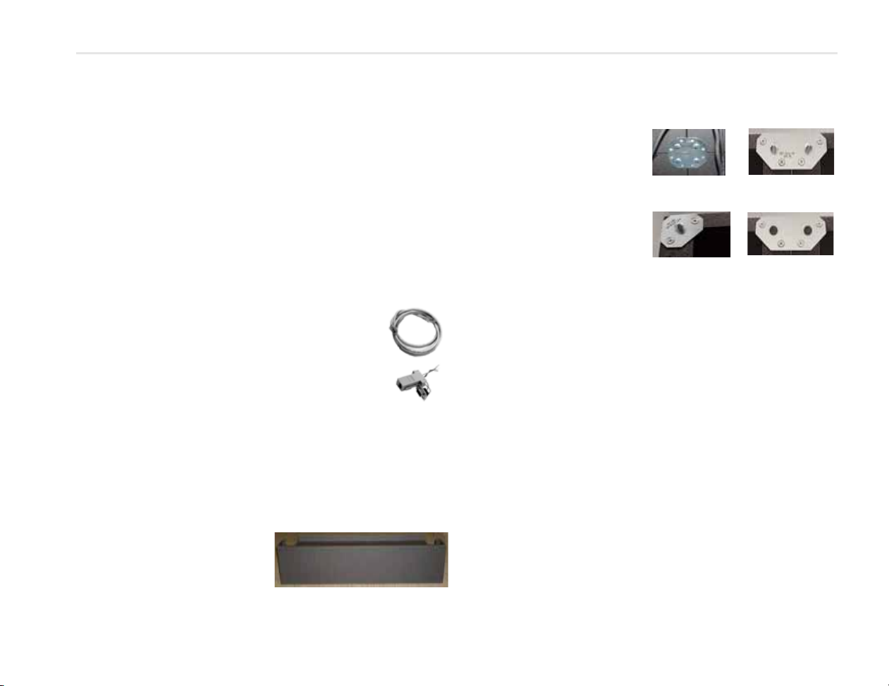
Checking Accessories
Center
Side Top-Bottom
(front shown)
Corner (front shown)
Side Top-Bottom
(rear shown)
Checking
3
Accessories With Each Display
Accessories
Check for the following items included in your accessory box:
• This guide and the Installation & Configuration Guide CD on the
back of this guide
• Remote control (with the batteries already installed)
• Power cord (for use in North America)
• VGA cable (15-pin cable for analog computer pictures)
•DVI-D cables
• Plastic spacers used for front access installations
• M8 x 8mm flathead Phillips screws (for screen brackets)
• Suction cup (used to open the screen after the wall is built)
Make sure you have the following customer-supplied items as needed to complete your installation:
• RJ45 to 9-pin adapter, if you will use RS232 commands to control the displays
• RJ45 cable, computer network type
• Component video cables
• S-video cables
• Shims to level the bottom of displays
Accessories With Each Order of Displays
The number of screen brackets included in an order of c50R/
c67Rs depends on the size and configuration of the proposed
video wall. The number of brackets required for your planned
wall are all packed in a separate accessory kit.
Bottom Row Screen Support
If you have a wall higher than
two units, this support provides
additional wall stability.
Brackets
The following brackets are
available:
• Center Screen Bracket
•Front or Rear Corner
Screen Bracket
•Front or Rear Side TopBottom Screen Bracket
Optional Accessories
Video Input Module (VIM)
Contains inputs for component, S-Video, composite and SDI
sources. This ships separately and is installed on site.
Option Key
Contains Planar’s Big PictureTM and/or Set it and Forget itTM (SiFi).
The SiFi feature includes Auto Color Balance (ACB) and the dual
lamp scheduling feature. The Big Picture lets you spread one
picture over the whole wall, or over part of it. SiFi allows you to
automatically adjust color balance over a whole wall of displays.
It also allows you to configure settings for automatic lamp
switching. The Option key ships separately and is installed on
site.
WallNet
Is a system of hardware and software that displays information
about a wall of displays on a network browser. It is primarily
used for monitoring, reporting and some control (for example,
manually powering displays on and off). WallNet is required for
Auto Color Balance.
Page 5
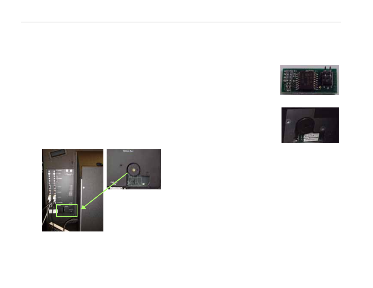
Installing the Option Key
The Option key for Planar’s Big PictureTM and/or for SiFi is
shipped separately and installed on site. The Option key can be
installed without removing the control board.
1 Attach a ground strap to your wrist and the chassis.
WAR NING! Failure to properly use a grounding strap can destroy sensi-
tive electronic components in the control board.
2 Turn off the power on the c50R/c67R and remove the
power cord.
WARNING! Always turn off power and remove the power cord when
adding or removing an electronic part.
3 Remove the two screws and the small plate on the bottom
of the control board.
4 Remove the Option key from its shipping pouch and anti-
static bag.
5 The Option key has six pins.
Plug the key into the socket on
the control board. Be sure all
six pins go in. If only one row of
pins is connected, the whole
display may not function.
6 The Option key is now installed.
7 Using the two screws you set
aside earlier, reinstall the
Option Key cover plate.
4
Installing the
Option Key
Page 6
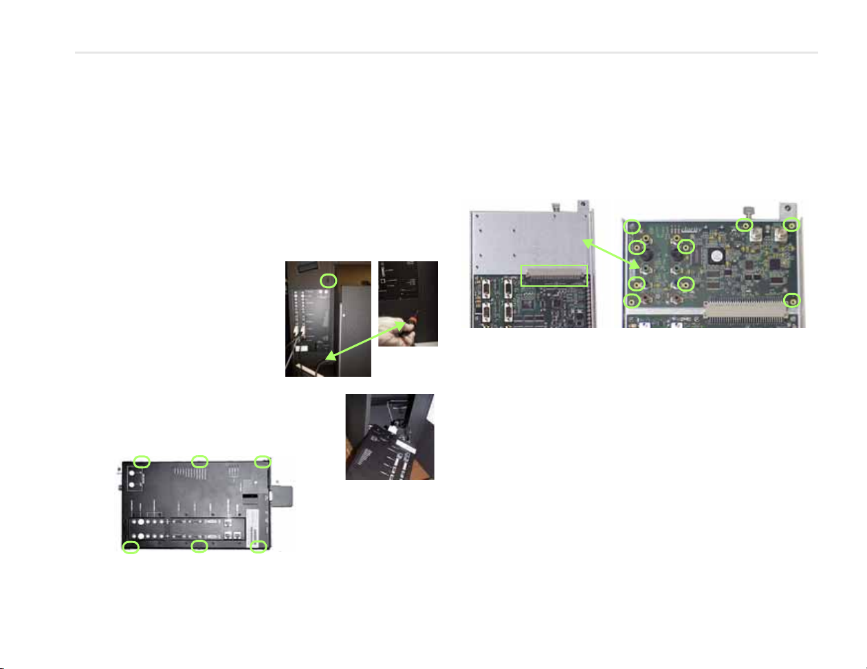
Installing the Video Input Module (VIM)
Connector
Installing the
VIM
5
The optional VIM is shipped separately and installed on site.
WARNING! Always turn off power and remove the power cord when
adding or removing an electronic part.
Removing the Control Board
1 Attach a ground strap to your wrist and the chassis.
WARNING! Failure to properly use a grounding strap can destroy sensi-
tive electronic components in the control board.
2 Loosen the screws on the
back of the display that hold
the control board in place.
3 Swing the control board to
about 45° and lift it off its pin
hinges. It will still be connected to two or more
cables at the bottom.
4 Bring the control board partly out the
opening and disconnect all the cables.
5 Remove six screws from the sides of the
covers.
6 Remove the DVI connector EMI shield. Use a 3/16" nut
driver. The EMI plate may be stuck to some EMI tape. Try
not to tear the tape.
7 Remove the cover of the control board. It is a snug fit.
Installing the VIM
1 Slide the VIM in its space and press it into its connector on
the main control board.
2 Install nine screws to secure the board.
3 Replace the control board cover. Check first to see that all
the LEDs are straight and none are bent over. Carefully lay
the cover all the way down over the control board, watching the LEDs to see that they are visible through their
holes.
4 Press the cover onto the control board; it is a snug fit.
5 Attach the cover using the 6 screws at the sides.
6 Install the two nuts and washers in the top right corner.
7 Replace the EMI shield at the bottom with the 3/16" stand-
off nuts.
8 Reconnect any cables you may have removed.
9 Replace the control board in the display. The hinge is two
pins on the display chassis and two holes on the control
board. Fit the top hole first. That pin is a little longer.
10 It is now safe to replace the power cord and turn on the
power.
Page 7

Wall, Tower or Banner Installation
As
seen
from
top of
unit
Installing the First or Bottom Row
Note: Detailed instructions for wall, tower or banner installation can
be found on the Installation & Configuration Guide CD.
1 Unpack the displays for the bottom row only. Do NOT
unpack screens yet. Check the contents. (page 3)
2 Make sure all VIMs and Option keys are installed on each
display. If you are building a tall array, it is easier to install
them while they are on the ground.
3 Release the optical engines from their shipping position.
4 For each unit, install a screen support.
5 Assemble the bottom row ONLY. Start by finding the high-
est part of the installation area. The easiest way to deter-
mine this is by placing shims with the bottom row of units
in place and seeing which unit is highest.
6 For front access systems only, affix plastic spacers on the
top of the chassis of the lower units before stacking. These
give just enough space to allow units to be removed with-
out scratching or damaging surrounding units.
7 Check for plumb, aligned and square; adjust the bottom
shims as needed.
Note:
It is important to get the first row right. Any mistake made here
will multiply as the wall goes up.
Installing the Second and Subsequent Rows
1 Unpack only the displays that will be in this row. (page 2)
2 Make sure all VIMs and Option keys are installed on each
display.
3 Release the optical engines from their shipping position.
(page 7)
4 For front access systems, put plastic spacers on the top of
the units, before stacking more units.
5 Assemble the next row on top of the previous row, start-
ing with the center unit and working out.
6 As each second-row unit is placed on the first row, tighten
the bolt-through captive screws in the bottom row to hold
the second row in place.
7 Confirm the units are still plumb, aligned and square.
Adjust bottom row shims as needed.
Note:
For units in the same row, check that the fronts are in a straight
line by pulling a piece of string tight across the row.
8 Install screen brackets as you go up. (page 3)
9 If you have a wall of three or higher, install tie backs to a
wall or other building structure to prevent tipping. Leave
them somewhat loose for now. For greater support, use
with rear Side Top-Bottom brackets.
10 Install cables. See page 9 and page 10.
11 When the wall is complete - aligned and square, all screen
brackets installed - install screens (page 8) starting with
the center bottom row and working out in the row, Install
screens on the next row up.
6
Wall & Tower
Installation
Page 8

Releasing the Optical Engine
Releasing the
7
The c50R/c67R is shipped with the optical engine in a lockeddown position. You must release it and put it in the operation
position before you can align the image to the screen. You normally do this before you install the c50R/c67R in a wall.
1 From the rear, remove the back panel.
2 Remove the shipping foam from the back of the unit; the
large piece first and then the small wedge.
3 Using a Phillips #2 screwdriver, remove two M4 x 16mm
keystone screws and washers.
Optical Engine
4 To gain access to the area below the rear lamp, remove the
lamp.
5 Remove three M4 x 8mm screws and fender washers.
6 Replace the rear lamp.
7 Replace the back panel.
Page 9

Installing Screens
Pin in the
slot in
screen
Hook in
screen
arm
Y-a xis
X-axis
Z-axi s
1 Using two people, remove the screen from the packing
case. Grab near the corners as you lift the screen from the
packing case.
We suggest you save the screen packaging until the entire array
Note:
is installed.
2 Cut open the protective envelope. Be careful not to
scratch the screen or the frame.
Caution: The screen is heavy, delicate and expensive. Take care when
handling.
3 Remove the screen from the envelope and carefully place
it aside. Notice there are two slots in the back edge of the
screen. The screen guide arms go into slots.
There is a label on the bottom of the screen.
Note:
4 Prepare the center unit in the bot-
tom row to receive a screen by pulling the support rails all the way out.
5 Using two people, lift the
screen at the sides. Hang
the screen on the screen
guide hooks. It is easier
to do this one side at a
time, with one person
holding still, and the
other person hanging
the screen on the hook.
6 Press the heel of your hand against all four corners of the
screen until the spring-loaded latches click into place.
Note:
You may have to lift the screen a little to get guide pins on the
screen brackets to fit into the holes in the back of the screen.
Caution: Don’t hit the screen hard; it can break.
7 Continue installing screens from the center out until you
have installed screens for an entire row.
8 Move to the next row up, and install a screen on the center
unit.
9 Repeat steps 1 through 8 until all screens have been
installed.
Fine Adjustment
If the screens are not flat with
each other, there is a z-axis
adjustment screw at the top
and bottom of the inside
edge of the screen. You must
open the screen to make this
adjustment.
You can also make x-axis (left
or right) and y-axis (up or
down) adjustments at the top
corners on both sides of the
screen. These can be adjusted
without opening the screen.
8
Installing Screens
Page 10

Connecting Source Cables
Connecting
Source Cables
9
All cabling for the c50R/c67R must be run through the rear of
the display. You can run cables as the rows go up or when the
installation is complete.
Connecting Sources
The three types of picture sources are:
• Analog computer (from UXGA down to VGA)
• Digital computer (Digital Video Interface, or DVI, digitally
connects computers to their monitors or interconnects to any
display)
• Video (optional with VIM)
• Composite (NTSC, PAL or
SECAM)
• S-Video (NTSC and PAL 50Hz or 60 Hz)
• Component (480i, 480p,
576i, 576p, 720p, 1080i)
• SDI (Serial Digital Interface
inputs from 480i to 1080p)
Each of these inputs have a separate loop-through output.
Loop-Through
For all the loop-throughs except digital, what goes in is what
comes out. Switching which connector is used for the displayed
picture does not change what comes from their output connectors. Whatever goes in Analog 1 In comes out Analog 1 Out; it is
not changed in any way, but it is buffered.
Digital Out is different. For the Digital Out connector, switching
inputs does change what comes out of it. The selected picture
from either Analog In or Digital In always comes out the Digital
Out connector in digital form.
Note:
The Digital Out signal does not strictly conform to the DVI
standard. Non-Planar units will not be able to display this signal.
The advantages of DVI are:
• DVI is less subject to picture degradation than analog methods
of loop-through. (Even with DVI, loop-through is not infinite.)
• DVI inputs require much less setup and adjustment. You adjust
the picture in the first unit only, the unit with the analog input.
Selecting the Correct Input
The following table gives you common examples of which
devices have which inputs. In terms of input quality, the table is
ordered from the most desirable input to the least desirable
input.
Input Found on the Following Devices
DVI Computers with digital out capability
SDI Studio quality video equipment
Analog Computers, laptops
RGB and RGBS from video processors or other profes-
sional equipment (may need BNC to DB15 adapter
cable). These may have separate sync, composite or
sync on green.
Component DVD players
Set top boxes (e.g. for cable TV or satellite TV)
Any YPbPr signal
S-Video DVD players
Set top boxes
VCRs
Composite TV tuners
VCRs
Set top boxes
Page 11

Connecting Power, Turning It On/Off
10
Connect Power,
Turn It On/Off
Each display may draw up to 2.0A at 115V or 1.0A at 230V. For
countries outside of North America, it is the responsibility of the
installer to provide the power supply cord certified for use in the
destination country.
The power switch and power
receptacle are located at the left
rear of the display.
Connect a power cable to the
power supply. The power supply
is auto-ranging, so it works with
any source from 100 to 240 VAC,
50 to 60 Hz.
About UPS Supplies
Some installations use a UPS Uninterruptible Power Supply.
Most UPS devices will work with
the c50R/c67R. Review the
power specifications of your UPS
device to make sure it is compatible with the c50R/c67R.
Turning Power On/Off
1 With the power cord attached, turn on the power switch
located on the back of the unit.
2 Wait a few seconds and make sure that the green LED
Ready light is on.
3 Turn on the c50R/c67R by aiming the
remote at the screen and pressing the
ON button.
It is normal to leave the power connected
Note:
and the power switch on all the time and turn the
lamps on and off as desired.
4 To turn off the c50R/c67R, press the OFF
button.
You cannot turn off the lamps and then immediately turn them
Note:
on again. The lamps will not light until the mandatory cool-down
period of a minute has elapsed.
Page 12

Using the Remote and Menus
Some of these “hot keys” go
directly to the most-used
menus. Some of them go to
several menus, if you push the
button more than once.
SOURCE, SETUP and CURTAIN
perform special actions
without menus.
Pressing the up/down
arrow keys moves the
select bar (yellow
highlight in the menus).
The –/+ (left/right)
arrow keys change
values in the selected
item. The right arrow
can also take you to the
next menu.
Pressing
MENU opens
the
MAIN MENU.
Pressing PREV reverts to the
previous menu.
Pressing
ENTER moves to the
next menu, when it has a rightpointing arrow, or it toggles
the highlighted item on and
off.
Main Menu
Picture
Size & Position
Aspect Ratio & Wall
Memory
Diagnostics
Advanced Options
Program Information
Using the
Remote & Menus
Using the Remote Control
The remote control works much like a remote control for a TV or
11
DVD player, but it does more. Among other things, it opens
menus, changes values and moves the image.
The remote control operates with IR (infrared) signals going to
the IR receiver, which is located behind the lower center of the
screen.
To open menus on the c50R/c67R, aim the remote at the screen
and press the desired button(s).
Using the Menus
The c50R/c67R’s menus and functions are arranged in groups
and can be accessed through grouped functions or by using
direct access keys. The starting point for accessing menus is the
MENU button on the remote.
1Press
2 Use the up/down arrow keys to move through menu
Some of the setups described in this Quick Start Guide will
explain how to navigate through specific menus. Most of the
menus are explained in detail in the Installation & Configuration
Guide CD.
MENU on the remote to display the MAIN MENU.
options. See explanations next to the remote control picture on this page for additional navigation information.
Page 13

Selecting a Source
In this guide, a source is any type of picture. It might be an analog computer image, a video processor, a VCR or DVD, or it
might be a DVI picture from a computer.
Selecting the Source Automatically
1 Press SOURCE on the remote. The c50R/
c67R goes to the next connector that
has a valid picture on it and displays
that picture.
2 If you want to select a different source,
press
SOURCE again to select the next
connector (that has a valid picture on
it) and display the picture.
If a connector does not have a valid source, the c50R/c67R
Note:
briefly displays that it has scanned that connector and then proceeds
to the next connector.
Selecting the Source Manually
1 Press FREQ/PHASE on the remote. The c50R/c67R displays
the
PICTURE menu for the current source.
Picture
Source Digital
Colorspace RGB
Vertical Frequency (frame locked) 60Hz
Horizontal Frequency 50.00kHz
Horizontal Resolution 1366
Vertical Resolution 768
Sharpness 4
2With
Note:
menu.
SOURCE highlighted, press the + button to open the
SOURCE submenu.
The SOURCE submenu displays to the right of the PICTURE
3In the SOURCE submenu, use the up/down arrow keys to
select the desired source.
4 When the desired source is selected, press
TURE menu changes to display the settings for that
ENTER. The PIC-
source.
When the Source is Familiar to c50R/c67R
When a “new” source is selected, the c50R/c67R looks through a
list of the last 10 picture types it used. If the “new” source is like
a previous one in this list (resolution, number of active lines,
etc.), the c50R/c67R uses the stored data and does not do anything in the
AUTO SETUP OPTIONS menu. This saves time, and
the picture is displayed faster without going through adjustments, which are visible on the screen.
Best Way to Change a Source
The best way to select a source is to recall a configuration your
installer has created for you. See the Installation & Configuration
Guide CD for more detailed information.
1 On the remote, press
2 Using the arrow keys, scroll to one of the numbered con-
figurations your installer has created for you.
3 Press
4With the
ENTER to show the RECALL SLOT menu.
RECALL NOW line selected, press ENTER. If the top
of the menu displays “Current,” the source is identical to
the settings stored in the memory slot.
SAVE. The RECALL menu displays.
Source
12
Selecting a
Page 14

Adjusting Levels for Analog Sources
Input Levels
Auto Black Level (offset)
Auto White Level (gain)
Center Point 64 124 99
Black Level (offset)-All 79
Red 89
Green 67
Blue 83
White Level (gain)-All 99
Red 99
Green 99
Blue 99
Adjust Levels for
Analog Sources
13
This page applies to analog RGB (computer) pictures only. The
levels are best adjusted semi-automatically.
For analog RGB pictures, the levels for black and white vary from
one computer to another, or from one video processor to
another. They even vary between video outputs from a multiple-output video card in a computer.
Your pictures will not look their best on the c50R/c67R until you
adjust for these differences. This is not about adjusting color or
contrast. It’s about telling the c50R/c67R what the computer or
processor means by black and by white.
Semi-Automatic Level Adjustment
1 Select a source in the PICTURE menu. Display an all-black
picture from the source computer. This must come f rom the
computer source that will be used for the program.
We suggest displaying a black screen using Windows® Paint.
Note:
2 To access the INPUT LEVE LS menu, press LEVEL.
3 Select
Note:
analog input, the color of the picture will change while it is working,
then it will change back to normal.
4 Display an all-white picture from the source computer.
5In the
6 The c50R/c67R is now adjusted to the black and white lev-
AUTO BLACK LEVEL and press ENTER. This menu line
says “Working…” until the process is complete.
When doing Auto Black and Auto White with an interlaced
INPUT LEVELS menu, select AUTO WHITE LEVEL and
press
ENTER. Wait for “Working…” to disappear.
els of this computer using this video card. If you change
computers or video output cards in the computer, you
must do this again.
Manual Level Adjustment
1 Select a source in the PICTURE menu. Display an all-black
picture from the source computer.
2
INPUT LEVELS menu, Press LEVEL on the remote.
3Select
Note:
zero. The idea is to just touch the zero level.
4 Display an all-white picture from the source computer.
5Adjust
6 Although it’s not required, it is recommended that you
BLACK LEVEL and adjust it up and down with the -/+
keys to make the three center point values go to zero.
Once any value reaches zero, use the individual colors
under black level to adjust the other two values to zero.
Do not go beyond the point where the minimum just goes to
WHITE LEVEL until the image maximums just go to
255. Once any value reaches 255, use the individual colors
under white level to adjust the other two values to 255.
save the configuration to a memory slot. See the Installation & Configuration Guide CD for more information.
Page 15

Adjusting Input Levels and Position
Input Levels
Brightness 140
Contrast 165
Saturation 150
Hue 128
Blue Only
Adjust
brightness so
you can’t see
the
difference
between
these two
marks
But you can you ca n
see the difference
between these two
marks
Adjusting Levels for Video Sources
Video sources are adjusted best if a color bar test pattern is
available from the video source: the DVD or VCR player. If not,
you will have to adjust by eye and the “feel” of the picture.
When a video source is selected, Auto Setup Options are not
Note:
available. Adjustments must be made manually.
Adjusting the Picture
1 Select a video source in the PICTURE menu.
2 Press
3 Adjust one of the following:
Adjusting With Color Bars
1 If possible, use a SMPTE color bar pattern from the video
2In the
3Adjust
4Adjust
5 Uncheck
LEVEL on the remote to open INPUT LEVELS.
• Any picture from the video source.
• Using a standard SMPTE color bar pattern from the source.
source you will use for the program material.
INPUT LEVELS menu, check BLUE ONLY. You should
see the alternate color bars, all of them blue.
SATURATION to make the outer two color bars
match. Match them in brightness; they will already match
in color.
HUE to make the inner two color bars match.
BLUE ONLY.
6 If the color bar pat-
tern has a pluge
(Picture Line-Up
Generation Equipment), you can use
it to adjust brightness. Pluge is used
to calibrate the
black level on a
video monitor.
7 Although it’s not
required, it is recommended that you save the configuration to a memory slot. See the Installation & Configuration
Guide for more information about saving memory slots.
Adjusting Position
Position moves the picture on the screen but does not move the
menus. Press
POSITION menu. The four arrow keys move the picture on the
screen.
The numbers for Horizontal and Vertical Position refer to the
number of pixels from sync to the first displayed pixel. These
numbers get smaller as the picture moves up and to the left.
The Horizontal Position number shows the number of pixels
from the beginning of H sync to the first active pixel. Because
there are many black pixels after H sync, this number will not be
zero when the picture is at the left border of the screen.
The Vertical Position number is the number of lines from V sync
to the first active line, so it will not be zero when the picture is at
the top of the screen.
SIZE/POS on the remote once to open the PICTURE
14
Adjusting Input
Levels & Position
Page 16

Color Balancing for Multiple Displays
Color Balancing
15
Color balancing makes the individual displays in an array show
the same colors. Colors vary slightly from one display to the
next, because of slight variations in the lamps and DLP engines.
Color balancing can compensate for this.
There are two methods to color balance a wall:
• Manual color balance
• Auto color balance (ACB)
Manual Color Balancing
To color balance, you only have to match whites and grays.
When you make all the displays look the same with white and
gray, all the other colors will look the same.
Caution: Do not match the colors of the displays with the Black and
White Level controls or with the video controls.
Caution: If you are color blind, even a little bit, do not manually color
balance your array. Have someone else color balance the wall.
1 Turn on all the displays in the array and let them warm up
for at least five minutes. The lamps must be thoroughly
warm before you color balance.
2 On each display, open the
pressing
Note:
If the array has never been color balanced, make sure you start
with the Native color temperature option on each display. If you don’t
need a specific color temperature, use Native, which is the brightest.
3 On each display, highlight TEST PATTERN and use the left/
right arrow keys until the menu displays
Always use the internal Test Patterns for color balancing, not an
Note:
external pattern.
MISC once on the remote.
COLOR BALANCE menu by
WHITE.
4 When all displays are white, find the least bright display in
the array. This will be the “baseline” display, and you will
not adjust it. All other displays will be adjusted to this
baseline display.
5 Choose a display next to the baseline display and adjust
its white values (red, green, and blue) to make it match the
baseline display. Concentrate on the center of the displays, not the adjacent edges.
6 Continue with other adjacent displays until all the displays
have the same appearance when white. Be careful not to
change the values of displays once you are satisfied with
them.
7 When all displays look the same when showing the White
test pattern, select the Gray test pattern in all displays.
8 Choose any display as the new baseline display. It does
not need to be the baseline display you used for white.
9 Adjust gray for all the displays until they match the base-
line display. Do one display at a time. Again, match the
center part of the picture, not the edges.
10 When all displays match in gray, close all the menus. The
test pattern automatically turns off.
Auto Color Balancing (ACB)
ACB automatically determines the display’s brightness of the
maximum range of colors (also called “color gamut”) that can be
created on all the displays in the array. Then ACB matches the
light output on all the displays and adjusts the color outputs.
You must have the optional WallNet device and optional Option
key with ACB. For more information about ACB and WallNet
installation, see the WallNet manual.
Page 17

Troubleshooting
Condition Priority Each block represents 0.2 seconds
Fan failed 1
R Amber
Lamp switcher
failed
2
R Amber
R
HV power supply
fan failed
3
R R Amber
Optical engine
failed
4
R R Amber R
Lamp failed
1
5
R R
Wait On (after cooling time elapsed)
6
R R Amber Amber
Wait (lamp cooling) 7
R R R R
One lamp failed
2
8
Amber R Amber
Lamp off (Auto Off) 9
Amber Amber R
Lamp off (Ready)
3
10
Amber Amber
Lamp striking
(starting)
11
Amber Amber Amber
Lamp on and all OK 12
Amber on continuously
R = Red To show the code press
MONITOR once on the remote.
1 If system is dual lamp, both lamps failed.
2 One lamp failed, or partial lamp switcher failure.
3 The lamp is off because of lamp timeout, or because the lamp switcher is moving.
Use the following troubleshooting tables to diagnose and
resolve common problems.
If your screen shows black or a test pattern
Do This Result Explanation/Further Action
1On the remote,
press MONITOR.
2 On the remote,
CURTAIN
press
once. If the message does not
disappear, press
CURTAIN again.
3 On the remote,
4Ensure the power
MENU until
press
the
MAIN MENU
appears.
cable is connected and the
switch is
No menu appears,
but I see flashing
lights
A menu appears Did the “Curtain or Test Pattern is displayed”
The message has
not disappeared
The message has
disappeared
The “source absent”
pane is visible
The source absent
pane is not visible
ON.
The lamps may not be lit. On the remote,
press ON.
If the screen is still black, see this page for
help interpreting the meaning of the flashing
lights.
message (in red) appear on the menu?
If it does not appear, go to 3.
If the message does appear, go to 2.
Check the remote control.
If the correct source does not appear, go to 3.
Make sure the correct source is selected by
SOURCE. If necessary, change to a
pressing
different source.
Make sure the source is on.
Make sure the cable between the source and
display is correctly connected at both ends.
Make sure the green LEDs on the control
board are lit.
If the screen is still a solid color, contact Planar’s Technical Support Department.
The source is displaying a solid color or a test
pattern.
Reconnect cable or turn on unit. If none of the
previous steps have resolved the problem,
contact Planar’s Technical Support Department.
c50R/c67R doesn’t respond to remote control
Possible Cause Possible Resolution
Power is not on. Confirm that the power cable is connected and
Remote batteries are dead or improperly installed.
Your installer or service provider has
disabled the remote control.
the power switch is on.
Replace or reinstall batteries.
Contact your installer or service provider.
Common On-Screen Codes
16
Troubleshooting
Page 18

Changing a Lamp
Front lamp
Rear lamp
This picture shows two lamps in a dual-lamp system
1 Using the remote, turn off the lamp and allow the cooling
fans to stop (about one minute) before proceeding.
WARNING! Never remove a lamp that is still lit.
Caution: In the dual-lamp system, it is possible to remove and replace
the lamp that is not being used while the other lamp is on. Be careful.
Use UV protective eye wear. Also, be aware that lamps are very hot and
can stay hot for some time after they are turned off.
2 Do one of the following:
• For front access units, open the screen.
• For rear access units, remove the rear panel.
3 Turn off the power switch and remove the power cord.
(For front access units, reach through the opening next to
the control board).
4 Lift the light shield.
5 If you have a dual lamp system and want to change the
front lamp, remove the three thumb screws and bracket
above the lamps.
6 Loosen the three captive thumb screws on top of the
lamp.
7 Lift the wire handle and pull the lamp straight up and out.
8 The picture (see below) shows a dual lamp system viewed
from the back. In this picture the front lamp is in the correct position for use, so you would probably want to
replace the rear lamp in this case.
9 Remove the new lamp from its packaging and plug it into
this space. Push it all the way down. Tighten the three
screws finger tight.
Note:
If the lamp is not pushed all the way down, the light path will
not be correct. This may cause a poor picture.
10 Close the light shield.
11 Reinstall the power cord and turn the unit on.
12 Do one of the following:
• For front access units, close the screen.
• For rear access units, replace the rear panel.
13 Reset the lamp hours (MAIN MENU > DIAGNOSTICS >
HOURS).
14 Color balance the wall (page 15).
Changing a Lamp
17
Page 19

Changing an Air Filter
18
Air Filter
Changing an
Changing an Air Filter (Rear Access)
The air filter is in the back of the unit below the power cord.
1 Using the remote, turn off the lamp and allow the cooling
fans to stop (about one minute) before proceeding.
2 Power down the unit and remove the power cord.
3 If necessary, lift up the cables so they are not in the way of
the air filter.
4 Pull straight up on the air filter to remove it.
5 Insert the new air filter. Arrows on the air filter should indi-
cate air flow direction, which is into the unit.
Changing an Air Filter (Front Access)
The air filter is in the rear of the unit below the power cord.
1 Using the remote, turn off the lamp and allow the cooling
fans to stop (about one minute) before proceeding.
2 Remove the front screen.
3 Loosen the captive screws at the top and bottom of the
control board.
4 If necessary, lift up and remove the control board from its
pin hinges.
5 Reach through to the front of the unit to power down the
unit and remove the power cord.
6 If necessary, lift up the cables so they are not in the way of
the air filter.
7 Reach through to the front of the unit and pull straight up
on the air filter to remove it. From the front, it might be
hard to see.
8 Insert the new air filter. Arrows on the air filter should indi-
cate air flow direction, which is into the unit.
9 Reposition the control board on its pin hinges.
10 Tighten the captive screws at the top and bottom of the
control board.
11 Reinstall the front screen.
Page 20

Declaration of Conformity
Conformity
19
Manufacturer's Name: Planar Systems, Inc.
Manufacturer's Address: 1195 NW Compton Drive
Beaverton, OR 97006
declares that the products
Model Numbers: c50RP/c67RP, c50RX/c67RX (DLP projection display)
conforms with the provisions of:
Council Directive 89/336/EEC and amended by 92/31/EEC and 93/68/EEC on Electromagnetic Compatibility;
EN55022:1998 Radiated and Conducted Emissions from IT Equipment
EN55024:1998 Immunity of IT Equipment
Including: EN61000-4-2 Electrostatic Discharge
EN61000-4-3 Radiated Immunity
EN61000-4-4 Electrical Fast Transients
EN61000-4-5 Line Surge
EN61000-4-6 RF Conducted Susceptibility
EN61000-4-8 Magnetic Field Immunity
EN61000-4-11 Voltage Dips and Interrupts
And: EN61000-3-2 Harmonic Current Emissions
EN61000-3-3 Voltage fluctuations and Flicker
Council Directive 73/23/EEC and amended by M1 and C1 on Low Voltage Equipment Safety:
EN60950:2001 Safety of IT Equipment
The Technical Construction File required by this Directive is maintained at the corporate headquarters of Planar Systems, Inc., 1195 NW Compton Drive, Beaverton,
OR 97006.
Note: This equipment has been tested and found to comply with the limits for a Class A digital device, pursuant to part 15 of the FCC Rules. These limits are
designed to provide reasonable protection against harmful interference when the equipment is operated in a commercial environment. This equipment generates,
uses, and can radiate radio frequency energy and, if not installed and used in accordance with the instruction manual, may cause harmful interference to radio
communications. Operation of this equipment in a residential area is likely to cause harmful interference in which case the user will be required to correct the
interference at his own expense.
Industry Canada (ICES-003): This Class A digital apparatus complies with Canadian ICES-003.
Cet appareil numérique de la classe A est conforme à la norme NMB-003 du Canada.
Any changes or modifications to the display not expressly approved by Planar could void the user's authority to operate this equipment.
Other Certifications: CE
 Loading...