

Page 1

Planar Clean Screen™II PC
User’s Manual
Model Number C3215
Page 2

™
PLANAR CLEAN SCREEN
II PC
Integrated Computer with LCD Color Display
USER’S MANUAL
Model Number C3215 and Options
Document Part Number C3DOC-2
Copyright 1999 © Planar Display Solutions. All rights reserved.
Page 3

The information in this document is subject to change without notice.
This publication may not be reproduced, stored in a retrieval system, or transmitted by any means without prior written
permission of Planar Display Solutions.
Clean Screen is a trademark and Planar and The Definition of Quality are registered trademarks of Planar Display Solutions.
IBM is a registered trademark of International Business Machines Corporation.
MS-DOS is a registered trademark of Microsoft Corporation.
MMX is a trademark and Intel and Pentium are registered trademarks of Intel Corporation.
Accutouch is a trademark of ELO TouchSystems.
All other trademarks and trade names are the property of their respective companies.
Please address any questions, comments, and suggestions to:
Planar Display Solutions
13950 SW Karl Braun Drive
P.O. Box 4001
Beaverton, Oregon 97076-4001 USA
Phone: (800) 893-8885
(503) 614-4100
Fax: (503) 614-4194
Planar International Ltd.
Olarinluoma 9
P.O. Box 46
FIN-02201 Espoo, Finland
Phone: 358 0 42001
Fax: 358 0 422143
http://www.pds.planar.com
ii Planar Clean Screen II PC User’s Manual
Page 4

REGULATORY INFORMATION
U.S. Federal Communications Commission (FCC) Requirements
The Planar Clean Screen II PC has been tested and found to comply with the limits for a Class
A digital device, pursuant to Part 15 of the FCC Rules. These limits are designed to provide reasonable protection against harmful interference when the equipment is operated in a commercial
environment. This equipment generates, uses, and can radiate radio frequency energy and, if not
installed and used in accordance with the instruction manual, may cause harmful interference to
radio communications. Operation of this equipment in a residential area is likely to cause harmful interference in which case the user will be required to correct the interference at his own
expense.
If this equipment does cause harmful interference to radio or television reception, which can be
detected by turning the equipment off and on, the user is encouraged to try one or more of the
following measures:
• Reorient or relocate the receiving antenna.
• Increase the separation between the equipment and the receiver.
• Connect the equipment into an outlet on a circuit different from the circuit to which the
receiver is connected.
• Consult an experienced radio/TV technician for help.
Canadian Emissions Requirements
This digital apparatus does not exceed the Class A limits for radio noise emissions from digital
apparatus set out in the Radio Interference Regulations of the Canadian Department of
Communications.
Le présent appareil numérique n˙émet pas de bruits radioélectroniques dépassant les limites
applicables aux appareils numériques de la classe A prescrites dans le Réglement sur le brouillage radioélectrique édicté par le ministére des Communications du Canada.
WARRANTY INFORMATION
Planar Display Solutions (Planar) warrants that the goods sold hereunder will be free of defects
in materials and workmanship, and such goods will substantially conform to the specifications
furnished by Planar, and to any drawings or specifications furnished to Planar by the Buyer if
approved by Planar. This warranty shall be effective only if Planar receives notice of such defect
or nonconformance during the period of the warranty. Planar’s sole and exclusive liability for
breach of warranty shall be, at Planar’s option, to repair or replace the Planar product(s) with
refurbished units or provide a credit to buyer in the amount of the purchase price.
Commencement of Warranty
The warranty period begins on the date of shipment.
Regulatory and Warranty Information iii
Page 5

Duration of Warranty
The goods sold hereunder are warranted for a period of two years from date of shipment unless
otherwise agreed to by Buyer and Planar. No extension of the warranty will be given during the
time the goods are in Planar’s possession.
Place of Repair or Replacement
In order to obtain service under this warranty, Buyer must notify Planar of the defect before
expiration of the warranty period and request a “Return Material Authorization Number.” If the
configuration has been modified in any manner, the product must be returned to its original configuration before any warranty service will be performed by Planar. No goods are to be returned
to Planar without prior authorization. Buyer will be responsible for packaging and shipping the
defective goods to the Planar Service Facility located at Beaverton, Oregon, with shipping
charges prepaid.
Limitation of Warranty
The foregoing warranty shall not apply to defects resulting from (a) improper or inadequate
maintenance by Buyer; (b) unauthorized modification of the goods; (c) operation of the goods
outside of the environmental specifications of the goods; (d) neglect, misuse, or abuse of the
goods; or (e) modification or integration with other goods not cov ered by Planar’ s warranty when
such modification or integration increases the likelihood of damage to the goods.
THE WARRANTY IS GIVEN BY PLANAR IN LIEU OF ANY OTHER WARRANTIES,
EXPRESS OR IMPLIED. PLANAR DISCLAIMS ANY IMPLIED WARRANTIES OF
MERCHANTABILITY OR FITNESS FOR A PARTICULAR PURPOSE. PLANAR’S
RESPONSIBILITY TO REPAIR OR REPLACE DEFECTIVE PRODUCTS IS THE
SOLE AND EXCLUSIVE REMEDY PROVIDED TO THE BUYER FOR BREACH OF
THIS WARRANTY. PLANAR WILL NOT BE LIABLE FOR ANY INDIRECT, SPECIAL, INCIDENTAL, OR CONSEQUENTIAL DAMAGES IRRESPECTIVE OF
WHETHER PLANAR HAS ADVANCE NOTICE OF THE POSSIBILITY OF SUCH
DAMAGES.
Technical Assistance
The warranty set forth above shall not be enlarged, diminished or affected by, and no obligation
or liability shall arise from Planar, any authorized dealer ,or any other person’s rendering of technical advice, assistance, or services in connection with the buyer’s order of the goods furnished
hereunder. The Buyer is not relying on Planar’s skill or judgment to select or furnish suitable
goods.
Installation
Planar makes no warranty with respect to any installation of Planar’s product(s) by Planar, any
authorized dealer, or any other person.
iv Planar Clean Screen II PC User’s Manual
Page 6

Table of Contents
Regulatory Information . . . . . . . . . . . . . . . . . . . . . . . . . . . . . . . . . . . . . . . . . . . . . . . . . iii
U.S. FCC Requirements . . . . . . . . . . . . . . . . . . . . . . . . . . . . . . . . . . . . . . . . . . . . . . . . . . . iii
Canadian Emissions Requirements . . . . . . . . . . . . . . . . . . . . . . . . . . . . . . . . . . . . . . . . . . . .iii
Warranty Information . . . . . . . . . . . . . . . . . . . . . . . . . . . . . . . . . . . . . . . . . . . . . . . . . . . iii
Commencement of Warranty . . . . . . . . . . . . . . . . . . . . . . . . . . . . . . . . . . . . . . . . . . . . . . . . iii
Duration of Warranty . . . . . . . . . . . . . . . . . . . . . . . . . . . . . . . . . . . . . . . . . . . . . . . . . . . . . .iv
Place of Repair or Replacement . . . . . . . . . . . . . . . . . . . . . . . . . . . . . . . . . . . . . . . . . . . . . . iv
Limitation of Warranty . . . . . . . . . . . . . . . . . . . . . . . . . . . . . . . . . . . . . . . . . . . . . . . . . . . . .iv
Technical Assistance . . . . . . . . . . . . . . . . . . . . . . . . . . . . . . . . . . . . . . . . . . . . . . . . . . . . . . . iv
Installation . . . . . . . . . . . . . . . . . . . . . . . . . . . . . . . . . . . . . . . . . . . . . . . . . . . . . . . . . . . . . . iv
Installation Guide . . . . . . . . . . . . . . . . . . . . . . . . . . . . . . . . . . . . . . . . . . . . . . . . . . . . . . viii
Before You Begin . . . . . . . . . . . . . . . . . . . . . . . . . . . . . . . . . . . . . . . . . . . . . . . . . . . . . . . viii
What’s in the box? . . . . . . . . . . . . . . . . . . . . . . . . . . . . . . . . . . . . . . . . . . . . . . . . . . . . . . viii
What’s in the IS Manager’s Kit? . . . . . . . . . . . . . . . . . . . . . . . . . . . . . . . . . . . . . . . . . . . . viii
What’s in this manual? . . . . . . . . . . . . . . . . . . . . . . . . . . . . . . . . . . . . . . . . . . . . . . . . . . . viii
What if I’m missing something? . . . . . . . . . . . . . . . . . . . . . . . . . . . . . . . . . . . . . . . . . . . . viii
Safety Instructions . . . . . . . . . . . . . . . . . . . . . . . . . . . . . . . . . . . . . . . . . . . . . . . . . . . . . . . . ix
Chapter One: The Installation Express . . . . . . . . . . . . . . . . . . . . . . . . . . . . . . . . . 1
Chapter Two: The Clean Screen II PC . . . . . . . . . . . . . . . . . . . . . . . . . . . . . . . . . . 2
Welcome . . . . . . . . . . . . . . . . . . . . . . . . . . . . . . . . . . . . . . . . . . . . . . . . . . . . . . . . . . . . . . . 2
Clean Screen II Facts . . . . . . . . . . . . . . . . . . . . . . . . . . . . . . . . . . . . . . . . . . . . . . . . . . . . . . 2
Front Panel . . . . . . . . . . . . . . . . . . . . . . . . . . . . . . . . . . . . . . . . . . . . . . . . . . . . . . . . . . . . . . 3
Connections (Bottom) . . . . . . . . . . . . . . . . . . . . . . . . . . . . . . . . . . . . . . . . . . . . . . . . . . . . . 3
Back Housing . . . . . . . . . . . . . . . . . . . . . . . . . . . . . . . . . . . . . . . . . . . . . . . . . . . . . . . . . . . . 4
Inside . . . . . . . . . . . . . . . . . . . . . . . . . . . . . . . . . . . . . . . . . . . . . . . . . . . . . . . . . . . . . . . . . . 4
Chapter Three: Hardware Installation and Replacement . . . . . . . . . . . . . . . 6
Removing the Back Housing . . . . . . . . . . . . . . . . . . . . . . . . . . . . . . . . . . . . . . . . . . . . . . . . 6
Installing Memory . . . . . . . . . . . . . . . . . . . . . . . . . . . . . . . . . . . . . . . . . . . . . . . . . . . . . . . . 7
Memory Map . . . . . . . . . . . . . . . . . . . . . . . . . . . . . . . . . . . . . . . . . . . . . . . . . . . . . . . . . . . . .8
Replacing the Hard Disk Drive . . . . . . . . . . . . . . . . . . . . . . . . . . . . . . . . . . . . . . . . . . . . . . . 9
Replacing the Battery . . . . . . . . . . . . . . . . . . . . . . . . . . . . . . . . . . . . . . . . . . . . . . . . . . . . .10
Replacing the Fuse . . . . . . . . . . . . . . . . . . . . . . . . . . . . . . . . . . . . . . . . . . . . . . . . . . . . . . .11
Mounting the Clean Screen II . . . . . . . . . . . . . . . . . . . . . . . . . . . . . . . . . . . . . . . . . . . . . . . 12
Table of Contents v
Page 7

Table of Contents
Chapter Four: System Setup . . . . . . . . . . . . . . . . . . . . . . . . . . . . . . . . . . . . . . . . . . 13
Connecting the Keyboard . . . . . . . . . . . . . . . . . . . . . . . . . . . . . . . . . . . . . . . . . . . . . . . . . . 13
Connecting Peripherals . . . . . . . . . . . . . . . . . . . . . . . . . . . . . . . . . . . . . . . . . . . . . . . . . . . . 13
PC Card Port . . . . . . . . . . . . . . . . . . . . . . . . . . . . . . . . . . . . . . . . . . . . . . . . . . . . . . . . . . . 13
Ethernet Connection . . . . . . . . . . . . . . . . . . . . . . . . . . . . . . . . . . . . . . . . . . . . . . . . . . . . . .13
Floppy Drive Connection . . . . . . . . . . . . . . . . . . . . . . . . . . . . . . . . . . . . . . . . . . . . . . . . . . 14
Power Supply . . . . . . . . . . . . . . . . . . . . . . . . . . . . . . . . . . . . . . . . . . . . . . . . . . . . . . . . . . . 14
Power Cord Selection . . . . . . . . . . . . . . . . . . . . . . . . . . . . . . . . . . . . . . . . . . . . . . . . . . . . . 14
USB Connection . . . . . . . . . . . . . . . . . . . . . . . . . . . . . . . . . . . . . . . . . . . . . . . . . . . . . . . . .14
External Speakers . . . . . . . . . . . . . . . . . . . . . . . . . . . . . . . . . . . . . . . . . . . . . . . . . . . . . . . . 14
Powering Up the Clean Screen II PC . . . . . . . . . . . . . . . . . . . . . . . . . . . . . . . . . . . . . . . . . . 15
Setup (<F2>) . . . . . . . . . . . . . . . . . . . . . . . . . . . . . . . . . . . . . . . . . . . . . . . . . . . . . . . . . . . 15
Driver Overview . . . . . . . . . . . . . . . . . . . . . . . . . . . . . . . . . . . . . . . . . . . . . . . . . . . . . . . . . 15
Brightness Control . . . . . . . . . . . . . . . . . . . . . . . . . . . . . . . . . . . . . . . . . . . . . . . . . . . . . . .15
Chapter Five: BIOS Setup . . . . . . . . . . . . . . . . . . . . . . . . . . . . . . . . . . . . . . . . . . . . . 16
Entering the BIOS Setup Program . . . . . . . . . . . . . . . . . . . . . . . . . . . . . . . . . . . . . . . . . . . 16
Setup Screens . . . . . . . . . . . . . . . . . . . . . . . . . . . . . . . . . . . . . . . . . . . . . . . . . . . . . . . . . . . 16
Main Menu . . . . . . . . . . . . . . . . . . . . . . . . . . . . . . . . . . . . . . . . . . . . . . . . . . . . . . . . . . . . . 17
Primary Master/Slave Sub-Menu . . . . . . . . . . . . . . . . . . . . . . . . . . . . . . . . . . . . . . . . . . . . 19
Boot Options Sub-Menu . . . . . . . . . . . . . . . . . . . . . . . . . . . . . . . . . . . . . . . . . . . . . . . . . . . 21
Advanced Menu . . . . . . . . . . . . . . . . . . . . . . . . . . . . . . . . . . . . . . . . . . . . . . . . . . . . . . . . .22
I/O Device Configuration Sub-Menu . . . . . . . . . . . . . . . . . . . . . . . . . . . . . . . . . . . . . . . . . 24
Power Management Menu . . . . . . . . . . . . . . . . . . . . . . . . . . . . . . . . . . . . . . . . . . . . . . . . . 26
Boot Menu . . . . . . . . . . . . . . . . . . . . . . . . . . . . . . . . . . . . . . . . . . . . . . . . . . . . . . . . . . . . . 28
Exit Menu . . . . . . . . . . . . . . . . . . . . . . . . . . . . . . . . . . . . . . . . . . . . . . . . . . . . . . . . . . . . . 29
Chapter Six: Care and Cleaning . . . . . . . . . . . . . . . . . . . . . . . . . . . . . . . . . . . . . . . . 30
Maintenance Tips . . . . . . . . . . . . . . . . . . . . . . . . . . . . . . . . . . . . . . . . . . . . . . . . . . . . . . . .30
Cleaning Tips . . . . . . . . . . . . . . . . . . . . . . . . . . . . . . . . . . . . . . . . . . . . . . . . . . . . . . . . . . . 30
vi Planar Clean Screen II Screen PC User’s Manual
Page 8

Table of Contents
REFERENCE GUIDE . . . . . . . . . . . . . . . . . . . . . . . . . . . . . . . . . . . . . . . . . . . . . . . . . . . . 31
Appendix A: Product Specifications . . . . . . . . . . . . . . . . . . . . . . . . . . . . . . . . . . 31
General Specifications . . . . . . . . . . . . . . . . . . . . . . . . . . . . . . . . . . . . . . . . . . . . . . . . . . . . 31
LCD Support . . . . . . . . . . . . . . . . . . . . . . . . . . . . . . . . . . . . . . . . . . . . . . . . . . . . . . . . . . . 31
VGA/Flat Panel Graphics Controller . . . . . . . . . . . . . . . . . . . . . . . . . . . . . . . . . . . . . . . . . 31
Cardbus Interface . . . . . . . . . . . . . . . . . . . . . . . . . . . . . . . . . . . . . . . . . . . . . . . . . . . . . . . . 31
Ethernet Support . . . . . . . . . . . . . . . . . . . . . . . . . . . . . . . . . . . . . . . . . . . . . . . . . . . . . . . . . 31
External Serial Ports . . . . . . . . . . . . . . . . . . . . . . . . . . . . . . . . . . . . . . . . . . . . . . . . . . . . . . 32
USB Ports . . . . . . . . . . . . . . . . . . . . . . . . . . . . . . . . . . . . . . . . . . . . . . . . . . . . . . . . . . . . . 32
Floppy Disk Drive Port . . . . . . . . . . . . . . . . . . . . . . . . . . . . . . . . . . . . . . . . . . . . . . . . . . . . 32
Optional Resistive Touch Screen Controller . . . . . . . . . . . . . . . . . . . . . . . . . . . . . . . . . . . . 32
Hot Keys . . . . . . . . . . . . . . . . . . . . . . . . . . . . . . . . . . . . . . . . . . . . . . . . . . . . . . . . . . . . . . 32
Keyboard Interface . . . . . . . . . . . . . . . . . . . . . . . . . . . . . . . . . . . . . . . . . . . . . . . . . . . . . . .32
Environmental Specifications . . . . . . . . . . . . . . . . . . . . . . . . . . . . . . . . . . . . . . . . . . . . . . . .33
Power Supply . . . . . . . . . . . . . . . . . . . . . . . . . . . . . . . . . . . . . . . . . . . . . . . . . . . . . . . . . . . 33
Appendix B: Programming Interface . . . . . . . . . . . . . . . . . . . . . . . . . . . . . . . . . . 34
Assigned and Available IRQs . . . . . . . . . . . . . . . . . . . . . . . . . . . . . . . . . . . . . . . . . . . . . . . 34
DMAs . . . . . . . . . . . . . . . . . . . . . . . . . . . . . . . . . . . . . . . . . . . . . . . . . . . . . . . . . . . . . . . . 34
I/O Address List . . . . . . . . . . . . . . . . . . . . . . . . . . . . . . . . . . . . . . . . . . . . . . . . . . . . . . . . . 35
Appendix C: Troubleshooting . . . . . . . . . . . . . . . . . . . . . . . . . . . . . . . . . . . . . . . . . 36
Anti-Virus Alert . . . . . . . . . . . . . . . . . . . . . . . . . . . . . . . . . . . . . . . . . . . . . . . . . . . . . . . . . 36
Troubleshooting Procedure . . . . . . . . . . . . . . . . . . . . . . . . . . . . . . . . . . . . . . . . . . . . . . . . . 36
Boot Failures . . . . . . . . . . . . . . . . . . . . . . . . . . . . . . . . . . . . . . . . . . . . . . . . . . . . . . . . . . . . 37
Problems At Initial System Startup . . . . . . . . . . . . . . . . . . . . . . . . . . . . . . . . . . . . . . . . . . . 38
Problems After the System Has Been Running Correctly . . . . . . . . . . . . . . . . . . . . . . . . . . . 38
Problems Running New Application Software . . . . . . . . . . . . . . . . . . . . . . . . . . . . . . . . . . . 39
Problems Operating PC Cards . . . . . . . . . . . . . . . . . . . . . . . . . . . . . . . . . . . . . . . . . . . . . . . 39
Problems with Ethernet . . . . . . . . . . . . . . . . . . . . . . . . . . . . . . . . . . . . . . . . . . . . . . . . . . . 39
Problems and Suggestions . . . . . . . . . . . . . . . . . . . . . . . . . . . . . . . . . . . . . . . . . . . . . . . . . 40
Error and Information Messages . . . . . . . . . . . . . . . . . . . . . . . . . . . . . . . . . . . . . . . . . . . . . 42
PCI Configuration Status and Error Messages . . . . . . . . . . . . . . . . . . . . . . . . . . . . . . . . . . 44
Resetting the System . . . . . . . . . . . . . . . . . . . . . . . . . . . . . . . . . . . . . . . . . . . . . . . . . . . . . .45
Appendix D: Touch Screen (optional) . . . . . . . . . . . . . . . . . . . . . . . . . . . . . . . . . 46
CMOS Configuration . . . . . . . . . . . . . . . . . . . . . . . . . . . . . . . . . . . . . . . . . . . . . . . . . . . . . 46
Appendix E: Technical Support . . . . . . . . . . . . . . . . . . . . . . . . . . . . . . . . . . . . . . . 47
For Service . . . . . . . . . . . . . . . . . . . . . . . . . . . . . . . . . . . . . . . . . . . . . . . . . . . . . . . . . . . . . 47
For Further Information and Driver Updates . . . . . . . . . . . . . . . . . . . . . . . . . . . . . . . . . . . . 47
vii
Page 9

INSTALLATION GUIDE
Before Y ou Begin
Installing and setting up your Clean Screen II PC is very straightforward. But before you get
started, there are some things you should know.
What’s in the box?
Each box will contain a Planar Clean Screen II head (that is, the integrated computer and LCD
display), three Torx drivers (sizes: T15, T20, T25), the external power supply, and the power
cord. Remove the equipment carefully and inspect for damage. Immediately notify the shipping
company if damage has occurred. Set aside the packing material for possible future use.
What’s in the
This manual and several 3.5" diskettes with all the display dri v ers necessary to install your Clean
Screen II PC to various Microsoft operating systems. (If you ordered your Clean Screen II PC
with a preloaded OS, then the drivers will already be installed on the hard disk.) The IS
Manager’ s Kit is sold separately from the Clean Screen II PC. If you need to purchase additional
kits, please call (503) 614-4100. Together, the Clean Screen II shipping box and the IS
Manager’s Kit contain everything you need for installation and setup.
IS Manager’s Kit
?
What’s in this manual?
This manual is an advanced guide for installation and setup. It is intended for Information
Services Department professionals. We are not going to tell you things you already know about
PCs. We will cover what is unique about a Planar Clean Screen II and what you need to know to
successfully install and set them up. We encourage you to look through the entire manual before
you begin. Even if you don’t need all the information right now, it is good to know where it is
for later reference.
What if I’m missing something?
If something is missing from the box, please contact us at (503) 614-4100 or (800) 893-8885.
There are, however, several other items you may need. In this manual we will assume you
already have the IS Manag er’s Kit, standard Planar mounting equipment for the Clean Screen II,
and a Planar 3.5" external floppy drive (for loading any necessary drivers). If you are missing
any of these, please check with your department. If necessary, you can contact us for more information or to order these parts.
viii Planar Clean Screen II PC User’s Manual
Page 10
Clean Screen II Mounts and Accessories P/N
12" wall mounted swing arm M3S12
Flush wall mount system (for head and keyboard cabinet) M3WC0
Flush wall mount system (head only) M3FHM
Roll stand only M3POLE
Roll stand with UPS M3POLE-PS2
IS Manager’s Kit C3DOC-2
IS Manager’s Kit, TOUCH C3DOC-TS
Keyboard cabinet with keyboard and mouse M3W00
External floppy drive C3FLOP
Safety Instructions
Your Planar Clean Screen II PC has been designed, assembled, and inspected to ensure both the
highest quality product and greatest level of safety for the user. To maintain both quality and
safety, you must follow the instructions in the manual and the following safety guidelines.
1. Read the safety and installation guidelines carefully.
2. Keep the manual handy for future reference.
3. Install and use the Clean Screen II only on a sturdy surface and in stable surroundings.
4. Use the Clean Screen II in dry environments only.
5. Do not block vents or other slots on the Clean Screen II housing.
6. Use only the power supply module included with the Clean Screen II.
7. Use and maintain the safety ground plug set (power cord) included with the unit.
8. After the Clean Screen II has been installed, secure all electrical cords out of the way to pre-
vent the unit from being pulled off the table or other accidental damage.
9. Turn off and unplug the Clean Screen II before removing the back housing to access internal
user serviceable parts.
10. Avoid placing the Clean Screen II or any of its cables on or near heat sources.
11. Clean Screen II and its power supply meet the UL2601 standard for cleaning in a hospital
environment. Please see Chapter Six: Care and Cleaning for details.
12. Before cleaning, or if the unit becomes wet for any reason, it is always best to disconnect
the unit from its power source.
13. Practice caution when moving the Clean Screen II to a different location. Use original pack-
aging whenever possible.
14. If the Clean Screen II does not power-up when the power is switched on, refer to the
Troubleshooting section of this manual in Appendix C and follow the directions. If the Clean
Screen II still does not work, immediately disconnect it from its power source and contact a
qualified service technician.
If this device is used in a medical facility, any application software used on the
Clean Screen II PC must be in the language of the user.
Installation Guide ix
Page 11
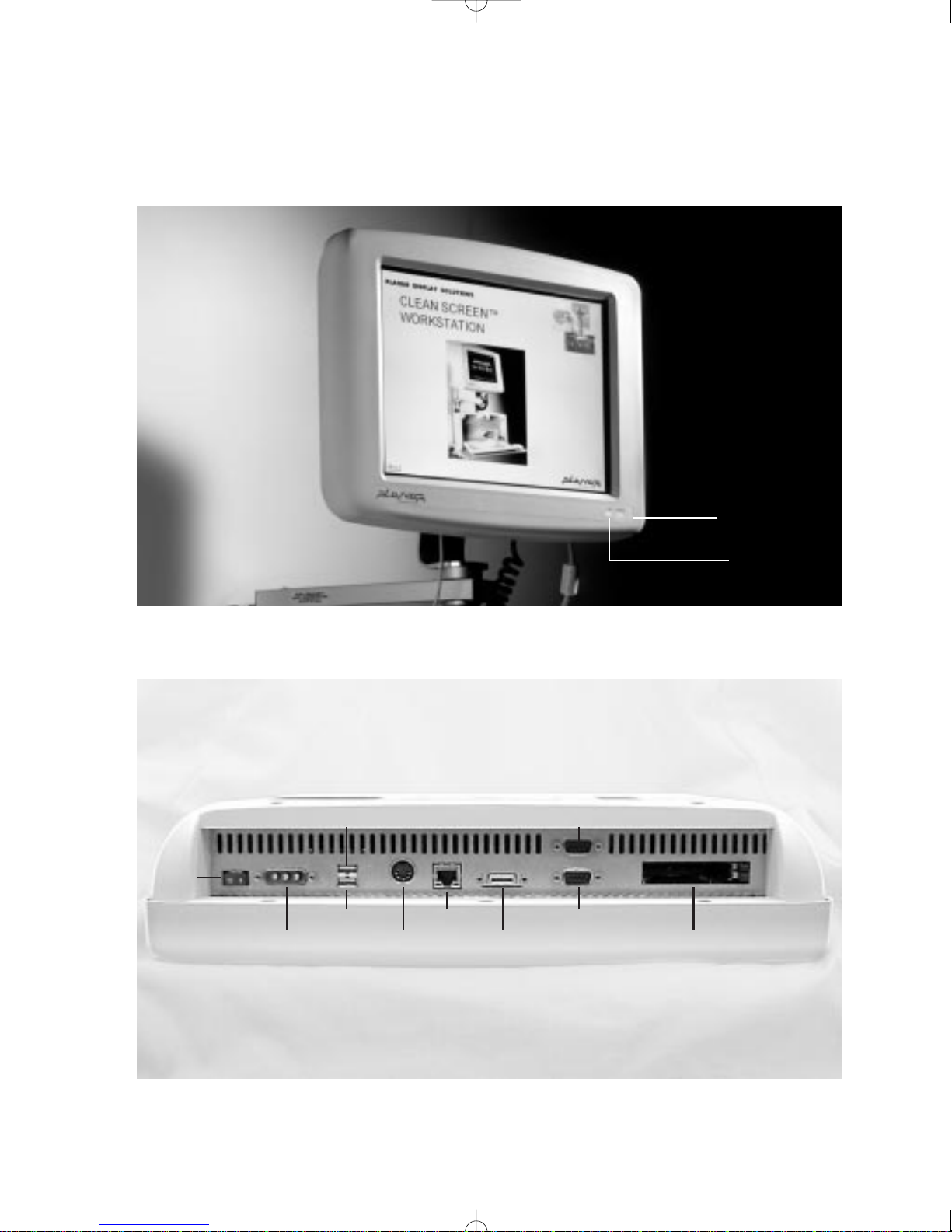
Front Panel
Figure 1
Power-on
Light
Hard
Disk
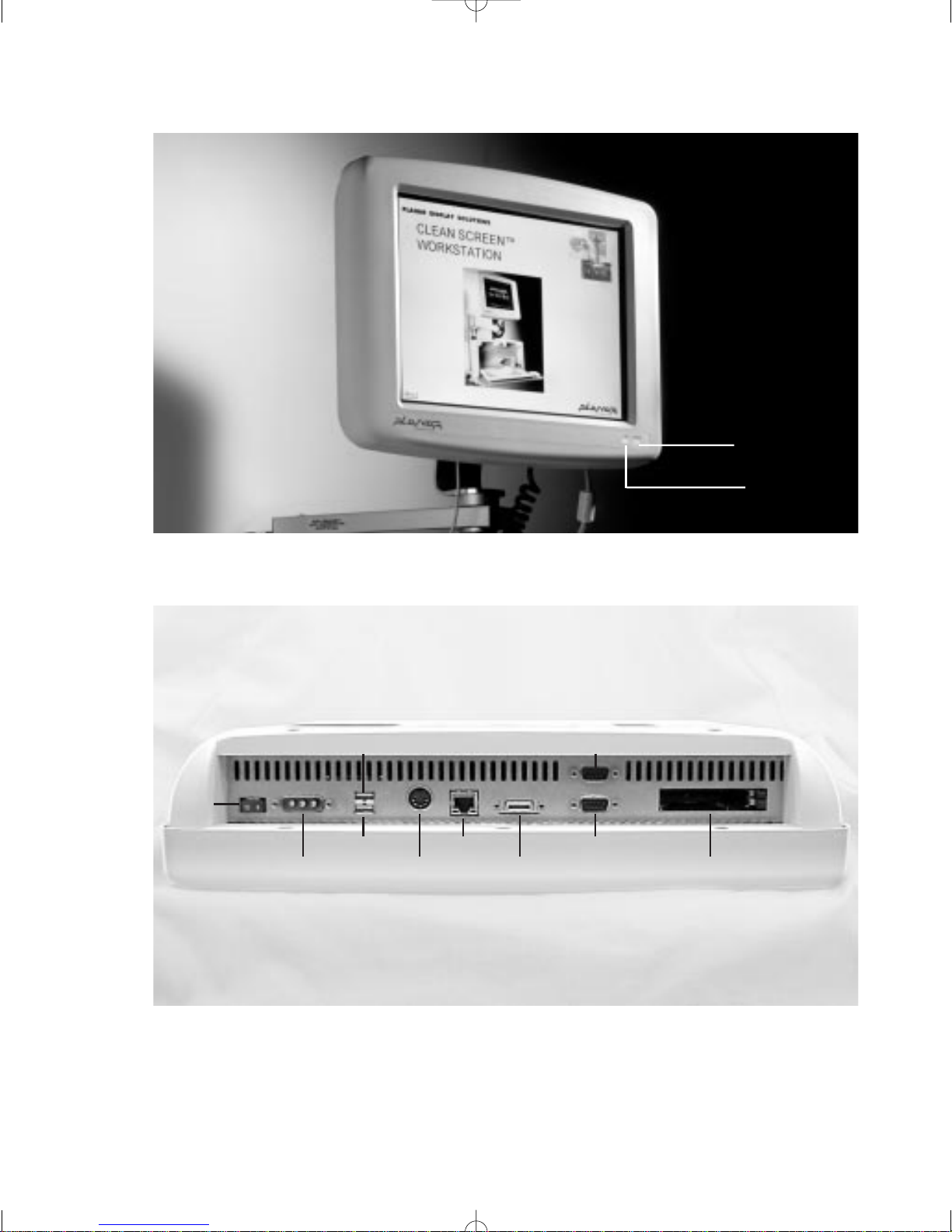
Connections (Bottom)
Power
Switch
Power
Connector
Figure 2
USB 1
USB 2 LAN
AT
Keyboard
Floppy
Connector
COM A
COM B
PC Card
Slot
x Planar Clean Screen II PC User’s Manual
Page 12
Chapter One: The Installation Express
If you are an experienced technician who has installed Clean Screen II PCs, then check out
Chapter One:The Installation Express. It covers the major steps. If you are the least bit unsure
of any step, please resume reading the rest of the manual.
1. Review the Before You Begin section of the manual — especially its Safety Instructions.
2. Unpack the Clean Screen II PC and save the packing.
3. If you need to add memory or a hard driv e,read Chapter Three: Hardware Installation and
Replacement for details.
4. Connect the keyboard, network, mouse, and any other peripherals. If you need help, refer to
Chapter Four: System Setup.
5. Before connecting the power, make sure the power switch is in the off (O) position. Connect
the power.
To prevent damage to the Clean Screen II, ensure correct orientation of the
power connector before plugging it into the unit. Always secure the connector
in place before turning on the Clean Screen II.
6. Turn on the unit.
7. Press <F2> immediately when prompted to enter the CMOS Setup. The screens are self-
explanatory. If a floppy disk is required for setup, you will need to enable drive “A.”
8. If your system was purchased without an operating system, you will need to use a boot disk
to create disk partitions and format the HDD before installing your operating system.
9. Load any drivers necessary for your system from the IS Manager’s Kit. Follow the
Readme.doc and other information on the disks.
10. Load your application software.
11. You may want to read the rest of the manual. There are many helpful details about your new
Clean Screen II PC, especially in the REFERENCE GUIDE section.
While the LCD display has a 25,000-hour back light life, the use of power
management to turn off the display when not in use is highly recommended.
Chapter One: The Installation Express 1
Page 13
Chapter Two: The Clean Screen II PC
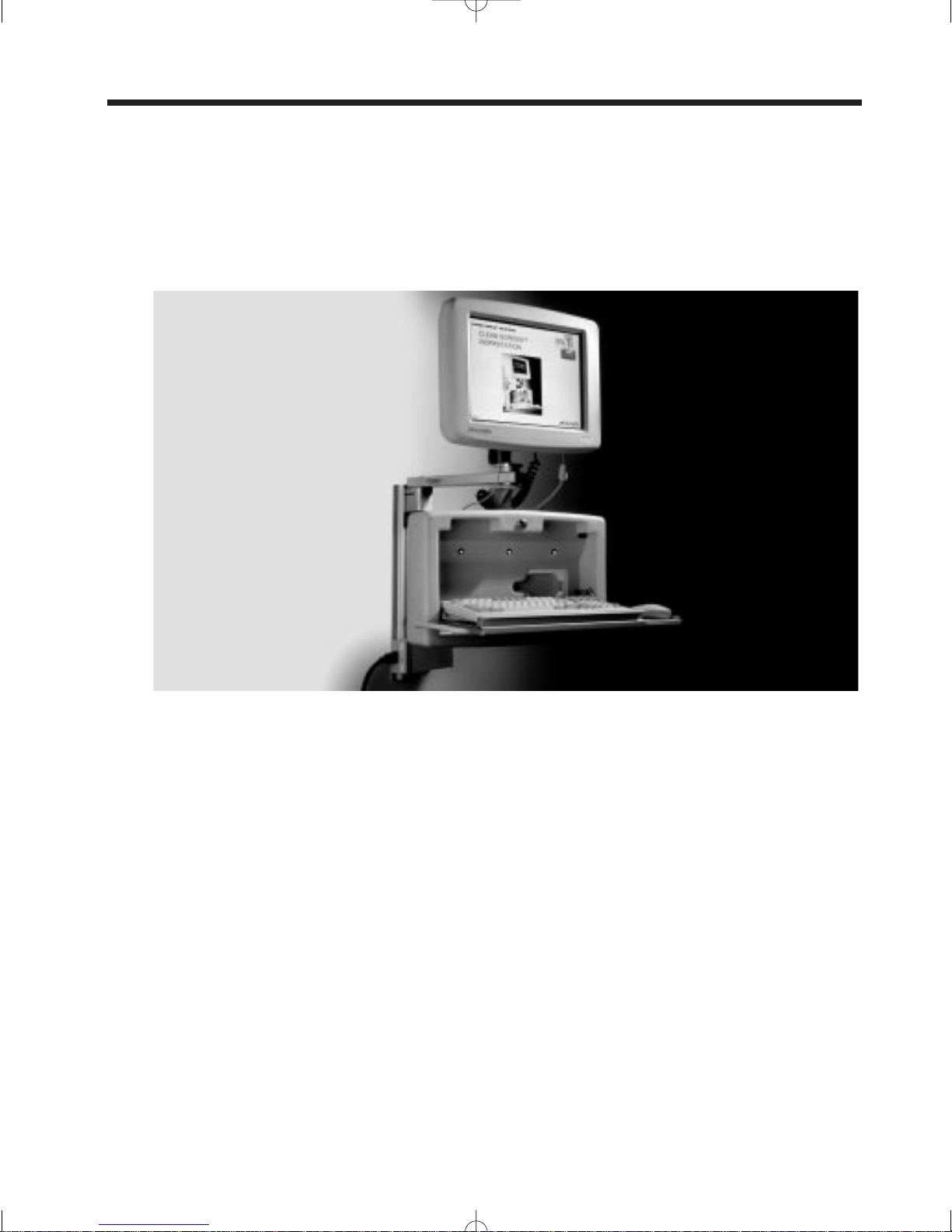
Welcome
Thank you for purchasing Planar’s Clean Screen II color LCD personal computer, an IBM®compatible PC integrated with a full color LCD VGA display. The Clean Screen II PC combines
Intel®Pentium®performance with state-of-the-art display technology to offer the most advanced,
rugged, and lightweight PC system commercially available.
Figure 3 — Planar Clean Screen II with keyboard cabinet.
Clean Screen II Facts
The Clean Screen II is an IBM compatible PC integrated with a color LCD screen. It supports
an Intel Pentium 266 MHz microprocessor and memory configurations to 256 MB FPM, EDO
DRAM, to 256 MB 66 MHz SyncDRAM. The system supports all EIDE and Ultra DMA/33
hard drives in the 3.5-inch form factor. The system includes a 15-inch AMLCD-TFT display
supporting resolutions of 640 x 480, 800 x 600, and 1024 x 768. The entire unit is rated to withstand shocks of up to 50 g, is powered by a single power supply, and is certified to meet the
UL2601.1 standard for safety. The system provides two Universal Serial Bus ports, two serial
ports, one AT keyboard port, one external floppy drive port, and one PC Card Type III expansion
socket. Additionally, the system provides onboard Ethernet connectivity with either 10 or
100Base-T support.
The system BIOS supports the Pentium processor with MMX™technology. The system BIOS is
year 2000 compliant, but it is recommended by the manufacturer to re-boot the system with the
century change.
Touch screen support is optional. If your unit has a touch screen, please refer to the manual
included on the disk with the touch screen drivers and Appendix D of this manual.
2 Planar Clean Screen II PC User’s Manual
Page 14
The Clean Screen II PC does not include an integrated floppy disk. There is provision for
externally accessing a floppy disk drive through a custom connector. This is for diagnostic and
service use only.
Front Panel
Power-on
Light
Hard
Disk
Figure 4
Connections (Bottom)
Power
Switch
Power
Connector
USB 1
USB 2 LAN
AT
Keyboard
Floppy
Connector
COM A
COM B
PC Card
Slot
Figure 5
Chapter Two: The Clean Screen II PC 3
Page 15
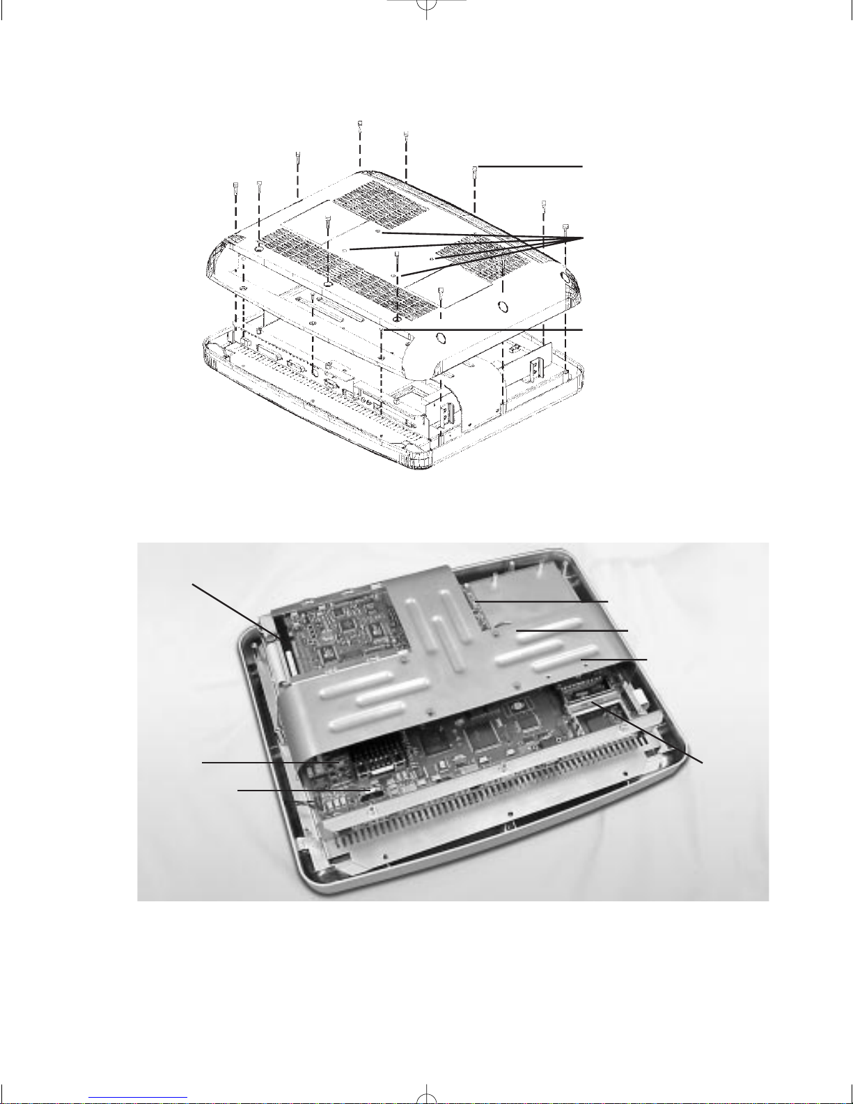
Back Housing
Figure 6 — Remove the back housing to gain access to the unit.
Twelv e T25 Torx screws
Four holes for standard
Planar mounting options (10⁄32)
Three T20 Torx screws
Inside
Figure 7
HDD
CPU
Touch Controller Board
(Optional)
Memory
Battery
PC Card
Slot
Fuse
4 Planar Clean Screen II PC User’s Manual
Page 16

Do not remove the T-Bar or the standoffs.
Their removal is not necessary to install or replace the battery, hard disk,
memory, or fuse . The display unit contained beneath the motherboard uses high
voltages.The display unit is not field serviceable and its connections are easily
damaged.
Static sensitive equipment.
Use proper grounding procedures while working inside the Clean Screen II.
Chapter Two: The Clean Screen II PC 5
Page 17
Chapter Three: Hardware Installation and
Replacement
This chapter refers to installing or replacing options within the Clean Screen II itself.
Instructions on installing the Clean Screen II onto a standard Planar mounting option will come
with the mounting equipment itself.
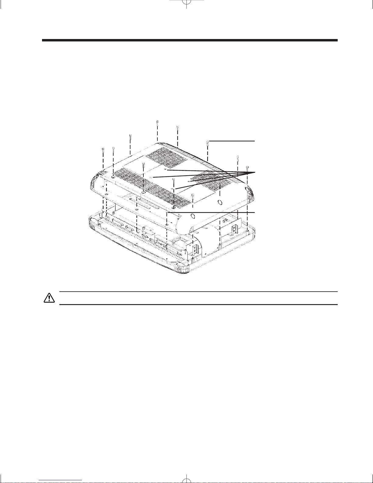
Removing the Back Housing
Twelv e T25 Torx screws
Four holes for standard
Planar mounting options (10⁄32)
Three T20 Torx screws
Figure 8
Power down unit first and disconnect it from the power source.
1. Power down unit first and disconnect it from the power source.
2. Use a static-free workstation.
3. Place Clean Screen II face down on a secure flat surface, using a cloth or other non-abrasive
material to protect the display.
4. Remove the twelve attachment screws from the back housing using a T25 torx driver.
5. Remove the three attachment screws from the back housing located near the connector ports
using a T20 torx driver.
6. Remove the back panel itself by gently lifting the bottom back edge first.
6 Planar Clean Screen II PC User’s Manual
Page 18
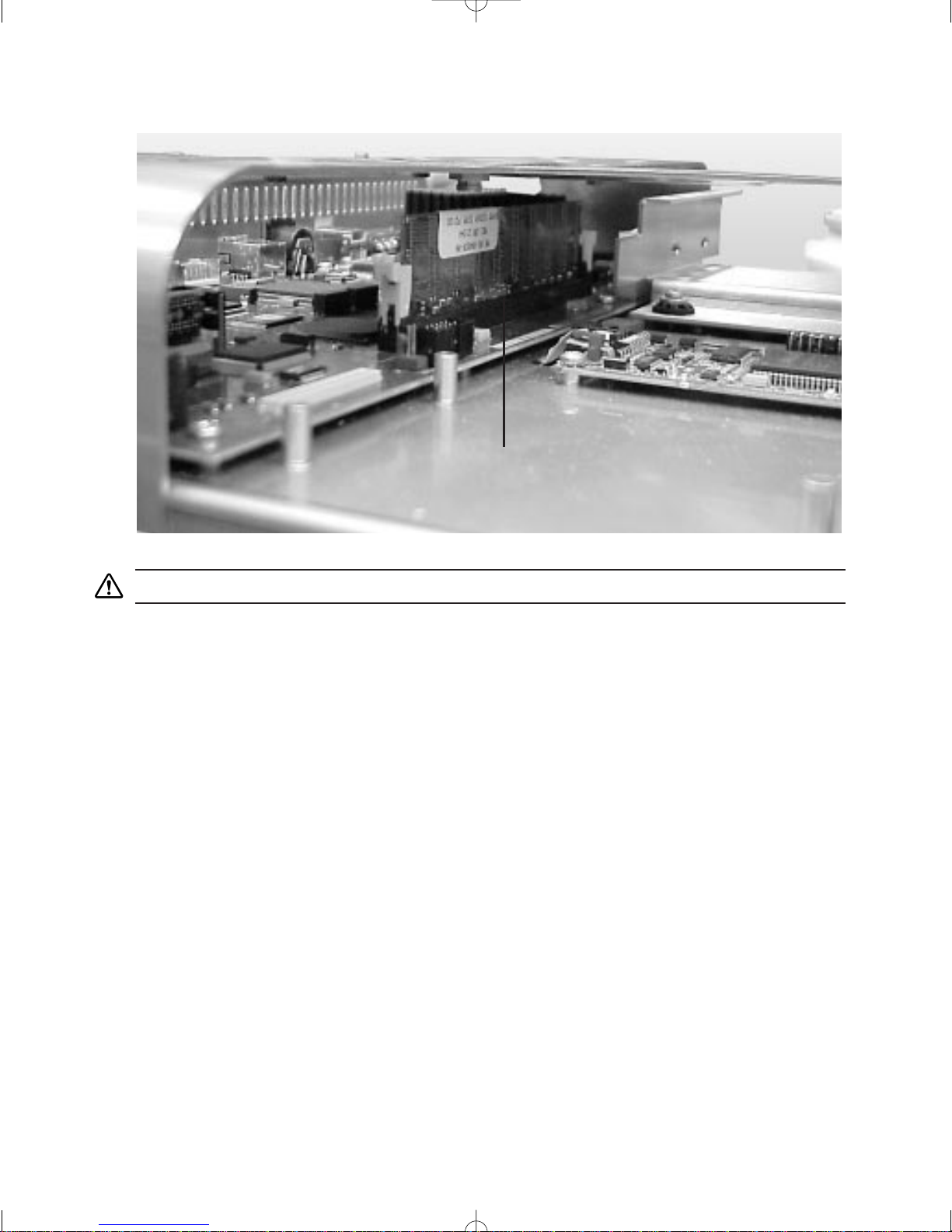
Installing Memory
Figure 9
Memory Slot with Memory Installed
Do not remove the T-Bar or standoffs.
To remove a memory module
1. Remove back housing as above.
2. Placing your hands on both sides of the T-Bar, gently open both side catches simultaneously
(apply pressure to the plastic part of the catch, not the metal spring).
3. The module will pop up.
4. Remove the memory module.
To install a memory module
1. Remove back panel as above.
2. Placing your hands on both sides of the T-Bar, gently insert the memory module into the
empty socket. Ensure correct orientation using the module notch located next to the contacts.
3. Push the module down gently until the side catches snap up into place, coaxing them if
necessary.
Technical Note: The memory module will only insert one way into the socket; do not force
it. If you meet with resistance, check the orientation of the module.
For correct memory configuration, see table on the following page.
Chapter Three: Hardware Installation and Replacement 7
Page 19

Memory Map
Range CPU address Region Cached
0 to 640K 00000000-0009FFFF DRAM yes
640K to 768K 000A0000-000BFFFF VGA memory no
768K to 816K 000C0000-000CBFFF Shadowed VGA BIOS yes
816K to 896K 000CC000-000DFFFF ISA bus or UBE yes
896K to 1M 000E0000-000FFFFF Shadowed System ROM BIOS yes
1M to 16M 00100000-00FFFFFF DRAM yes
If no DRAM, ISA or PCI memory no
16M to 64M 01000000-0FFFFFFF DRAM yes
If no DRAM, PCI no
64M to (4.0G–512K) 10000000-FFF7FFFF PCI no
Top 512K to Top 16K FFF80000-FFFFFFFF FBD no
8 Planar Clean Screen II PC User’s Manual
Page 20

Replacing the Hard Disk Drive
HDD mounting location
HDD Power
HDD Interface Cable
Figure 10
Removing the existing hard disk
1. Remove the back housing as above.
2. Locate the hard disk.
3. Remove the four screws that secure the hard disk to the hard disk cage.
4. Gently detach the hard disk power and I/O cable from the hard disk.
5. Slide the hard disk out of the cage.
Installing the new hard disk
1. Slide the hard disk into the cage so its four bottom-mount screws face upward.
2. Using the supplied 8-32 x 3⁄8" Phillips head screws, attach the hard disk to the hard disk cage.
3. Gently plug the I/O cable into the slotted I/O jack on the hard disk.
4. Gently plug the power cable into the hard disk power jack.
5. Replace the back cover before you power up the unit.
You will need a Phillips screwdriver with a #2 magnetic tip to complete this
process.
Static sensitive equipment.
Use proper grounding procedures while working inside the Clean Screen II.
To prevent damage to the Clean Screen II ensure correct orientation of the
I/O cable before plugging it into the I/O jack on the hard disk.
Chapter Three: Hardware Installation and Replacement 9
Page 21

Replacing the Battery
Battery
(Rayovac BR2335 or equivalent)
Figure 11
Battery: Rayovac BR2335 or equivalent.
1. Remove the back housing as above.
2. Gently pulling up on the battery bracket, remove the old battery.
3. Slide in a new battery. Dispose of the old battery in compliance with local regulations.
4. Upon startup, the system defaults will load. Enter Setup and go to the Exit menu to restore
the CMOS settings saved in your flash memory. See Chapter Five: BIOS Setup for details.
Technical Note: Before removing the battery you must ensure the CMOS is backed up in
flash memory. See Chapter Five: BIOS Setup.
10 Planar Clean Screen II PC User’s Manual
Page 22

Replacing the Fuse
Fuse (F5)
Bussman GDA-5A, 5 A
Figure 12
Replace fuse
(F5) by prying
from socket using a
small standard screwdriver
Use only the fuse specified below to prevent damage to the Clean Screen II.
Fuse: F5 Bussman GDA-5A, 5 A
1. Remove the back housing as above.
2. Using a small (jeweler-type) flat screwdriver, gently pry up on the fuse.
3. Snap in a new fuse that meets the above specifications.
Chapter Three: Hardware Installation and Replacement 11
Page 23

Mounting the Clean Screen II
16.29
0.42 0.42
0.55 0.55
0.35
5.76
3.92
∅0.22 ∅0.22
∅0.22 ∅0.22
4.75
3.502.60
0.35
0.610.61
4.65
12.78
Figure 13 — The back of the Clean Screen II, showing the location of mounting holes.
Planar offers a variety of mounting options. If you are using one of these, please refer to the
instructions included with your mounting hardware. If you are providing your own mounting
hardware, please follow these simple guidelines:
1. Use the drawing above to create a template for greater accuracy in locating the mounting
holes on your hardware.
2. Mount the Clean Screen II in such a way as to NOT block the rear cooling vents. Planar recommends a minimum of 1" rear clearance.
3. Use only mounting hardware that complies with OSHA, NFPA, and local as well as country
building codes.
4. Ensure the weight or load limit of the mount is 3 times the weight of the Clean Screen II, or
approximately 42 pounds.
5. Follow and comply with the vendor’s mounting instructions.
6. Use four (4) 10⁄32 x 1⁄2" stainless steel screws. If the thickness of the material you are mounting
to requires the use of longer screws, simply add that thickness to the 1⁄2 " screw length. Do not use
any screw that will protrude more than 3⁄8" into the back of the Clean Screen II.
12 Planar Clean Screen II PC User’s Manual
Page 24

Chapter Four: System Setup
Attach the keyboard and all peripherals before you power up the unit. All connections are made
at the bottom of the unit. If you have not yet attached the Clean Screen II PC to a standard mounting bracket, then lay the unit face down before you attach the keyboard and peripherals. Be sure
to use a non-abrasive cloth or other material to protect the face plate.
Power
Switch
Figure 14
Power
Connector
USB 1
USB 2 LAN
AT
Keyboard
Floppy
Connector
COM A
COM B
PC Card
Slot
Connecting the Keyboard
Your Clean Screen II can use any AT style keyboard. USB ports are also provided to support
USB keyboards.
Connecting Peripherals
Mouse
The Clean Screen II PC uses a serial type mouse. COM A is the default. A USB mouse can be
used with the USB port.
Printer
Printer support is provided through USB.
PC Card Slot
The Clean Screen II allows the connection of one Type III PCMCIA or PC Card or the use of
two Type I or Type II PCMCIA or PC Cards.
Ethernet Connection
The Ethernet connector is a right angle RJ-45.
Chapter Four: System Setup 13
Page 25

Floppy Drive Connection
Please note that this is NOT a standard floppy drive connection. The Clean Screen II is not
designed for regular use with an external floppy drive. The connector will only allow use of a
Planar 3.5" external floppy driv e and is intended only for diagnostic and service use. If you need
to load drivers for your operating system or other programs, you will need to obtain the correct
drive. See What if I’m missing something? in the Before Y ou Begin section.
If this device is used in a medical facility, any operating systems or programs
used are required to be in the user’s language.
Power Supply
If you will be using AC po wer , you will need to use the AC po wer supply adapter that was packed
with your Clean Screen II. If you will be using a Planar mounting stand with batteries, you will
use its power connector. To prevent accidental power disconnect, always secure the power plug
into the jack using the attached thumb screws.
Power Cord Selection
The Clean Screen II AC power supply adapter has been provided with a “Hospital Only” or
“Hospital Grade” type cord and plug. The plug has NEMA 5-15 approval. In the event it
becomes necessary to replace the power cord, it is important to select a “Hospital Only” or
“Hospital Grade” type cord and plug.
USB Connection
The dual stacked USB port connectors are mounted on the I/O shield.
External Speakers
Speakers are supported through USB.
14 Planar Clean Screen II PC User’s Manual
Page 26

Powering Up the Clean Screen II PC
Figure 15
Power-on
Light
Hard
Disk
Power On
Once the keyboard, mouse, power , and all peripherals have been connected, use the power switch
located beneath the power-on indicator to power up the unit.
Always power down the unit before you connect or disconnect any peripheral.
Setup (<F2>)
When the screen first writes, press <F2> on the keyboard to enter the CMOS Setup menu. Refer
to the next chapter for details.
Driver Overview
If you ordered the Clean Screen II PC with an operating system pre-loaded, then the display,
network, and touch drivers will already be loaded on the hard disk. Otherwise you will need to
check the floppy disks that came with the IS Manager’s Kit for the appropriate drivers. You will
find documentation and instructions in the Readme files stored on the disks.
Brightness Control
Display brightness can be controlled either by a hot key sequence of control–alt–F1 to increase
brightness, or control–alt–F2 to decrease brightness. Some operating systems may provide additional brightness adjustment.
Chapter Four: System Setup 15
Page 27

Chapter Five: BIOS Setup
The Setup program customizes the way the Clean Screen II PC uses the hardware features of its
BIOS (Basic Input/Output System). The Setup data is stored in CMOS and guides the computer
every time it is turned on. A special feature of the Clean Screen II PC is its ability to also store
the Setup information in flash memory, so Setup information can be recovered by the system
should the CMOS become corrupted. See the Exit menu section for details.
Entering the BIOS Setup Program
When you first boot up the Clean Screen II PC, there is a short-time window during which a
message is displayed telling you to Press F2 to enter Setup. Press and hold <F2> to enter Setup.
Setup Screens
The System BIOS Setup menus are the standard Phoenix NuBIOS 4.06 (with plug-and-play and
PCI support) screens with RadiSys extensions. A legend at the bottom of each screen provides
information for the user to manipulate setup options.
Use the up and down arrow keys to move the cursor from field to field, and the right and left
arrows to move from menu to menu. If the arrow keys are used to leave a menu and then return,
the active field is always at the beginning of the menu. Fields with a triangle to the left are
sub-menu headings; pressing <enter> when the cursor rests on one of these headings opens that
sub-menu. Within the sub-menu, most fields allow the user to flip through available choices by
pressing the <+> and <-> keys. Once the desired entry has been selected, use the up or down
arrow to move the cursor to the next field.
There are four menus: Main, Advanced, Power, and Exit. Note that item specific Help is provided whenever an item is selected. In this manual we will only detail the more important
sub-menus and choices.
Accessed from the Main screen, a Boot Delay option is added to the Boot Options screen and
allows the User to specify the boot delay in seconds. The Boot Delay is the only mechanism that
prevents a boot failure on slow devices.
The System BIOS also supports advanced features such as 32-bit disk I/O, Block and Fast
Programmed I/O, Ultra DMA/33, and the Intel/Microsoft INT13 disk extensions. These features
are automatically configured in the IDE setup menus if the System BIOS has determined
(through autotyping information) that the installed hard disk is capable of supporting them.
16 Planar Clean Screen II PC User’s Manual
Page 28

Main Menu
Main Advanced Power Boot Exit
PhoenixBIOS Setup Utility
System Time: [16: 17: 18]
System Date: [03/01/99]
Legacy Diskette A: [Not installed]
©
Primary Master: (1705MB)
©
Primary Slave: (None)
©
Memory Cache:
©
Boot Options:
©
UBE Shadow Control:
©
Boot-time Diagnostic Screen: [Enabled]
System Memory: 640 KB
Extended Memory: 64512 KB
F1 Help ↑↓ Select Item -/+ Change Values F9 Set Defaults
ESC Exit ↔ Select Menu Enter Select
©
Sub-Menu F10 Save and Exit
Item Specific Help
<Tab>, <Shift-Tab>, or
<Enter> selects field.
Figure 16 — Main BIOS Setup menu.
The first screen you’ll see is the Main menu.
System Time and System Date
These values are changed by moving to each field and typing in the desired entry. The TAB key
moves from hours to minutes to seconds, or from months to days to years.
Legacy Diskette A:
This field specifies the type of floppy disk installed as drive A:. Possible settings are
1.44/1.25 MB, 31⁄2; 360 KB; 1.2 MB; 720 KB; and Disabled. The default is 1.44/1.25 MB, 31⁄2.
Primary Master and Primary Slave Sub-Menus
These fields are headings for menus that allow entering complete disk drive information.
Usually, if your hard disk has not been defined, you will press <enter> at the IDE Adapter 0
Master sub-menu. There you can select Autotype Fixed Disk to allow the system to detect the
drive type automatically. The entry in the Main menu shows the drive selected.
Memory Cache Sub-Menu
The term memory cache refers to the technique of caching BIOS images.
UBE Shadow Control Sub-Menu
The options under this menu enable up to three user BIOS extensions and specify a source,
destination shadow address, and size.
Chapter Five: BIOS Setup 17
Page 29

Boot Options Sub-Menu
This sub-menu allows changing the boot delay for slow hard drives. The Boot Delay option is
used to set the system to delay booting for a time period expressed in seconds from 0 through 255.
This allows for long startup times on boot devices that spin up slowly. The default is 0 seconds.
Boot-Time Diagnostic Screen
This field specifies whether or not a boot-time diagnostic screen of the BIOS boot progress is
displayed during BIOS POST. The options are Enabled and Disabled. The default for this field
is Disabled.
System Memory
This field is not editable and displays the amount of conventional memory (below 1 MB).
No user interaction is required.
Extended Memory
This field is not editable and displays the amount of extended memory (above 1 MB). No user
interaction is required.
18 Planar Clean Screen II PC User’s Manual
Page 30

Primary Master/Slave Sub-Menus (under Main Menu)
The system supports two IDE devices. The following menu is representative of the menus for
each of these devices. The detailed characteristics for each connected drive is available in this
sub menu.
PhoenixBIOS Setup Utility
Primary Master/Slave Sub-Menus
Autotype Fixed Disk: [Auto]
Multi-Sector Transfers: [Disabled]
LBA Mode Control: [Disabled]
32-Bit I/O: [Disabled]
Transfer Mode: [Standard]
Ultra DMA Mode: [Disabled]
USB Legacy Support: [Disabled]
F1 Help ↑↓ Select Item -/+ Change Values F9 Set Defaults
ESC Exit ↔ Select Menu Enter Select
Figure 17 — Primary Master/Slave sub-menu.
©
Sub-Menu F10 Save and Exit
Item Specific Help
<Tab>, <Shift-Tab>, or
<Enter> selects field.
Autotype Fixed Disk
This option is used when setting up new disks. It allows Setup to determine the proper settings
of the disk for drives that comply with ANSI specifications. The ENTER key is used to invoke
this function.
Existing (formatted) disks must be set up using the same parameters that were originally used at
the time the disk was formatted. The specific cylinder, head, and sector information as listed on
the factory label must be manually entered on this screen using a User type described below.
Type
None is selected if there is no IDE hard disk drive for this adapter . In cases where there is an IDE
disk but the Autotype feature cannot be employed, then the User type is selected and the correct
drive values for cylinders, heads, sectors/track, and write precompensation are entered. For
MultiBoot II the selections for this field are: Auto, ATAPI Removable. IDE Removable, CD-
ROM, User, and None. The default is Auto.
Multi-Sector Transfers
This option allows the user to configure the System BIOS to read ahead by the specified number of sectors whenever a disk access is performed. This has the effect of reading more data at
once and reduces the absolute number of discrete disk reads performed by the operating system,
thus increasing system performance. The possible selections are Disabled, 2 sectors, 4 sectors,
8 sectors, or 16 sectors. Note that autotyping may change this value if the hard disk reports that
it support block accesses. The default is Disabled.
Chapter Five: BIOS Setup 19
Page 31

LBA Mode Control
When enabled, this option allows the System BIOS to reference hard disk data as logical blocks
instead of using the traditional Cylinders/Heads/Sectors (CHS) method. This option can only be
used if both the hard disk being configured and the operating system support Logical Block
Addressing (LBA). If disabled, then CHS mode is used. Note that autotyping may change this
value if the hard disk reports that it supports LBA. The default is Disabled.
32-Bit I/O
This option allows the System BIOS to access the hard disk controller with 32-bit I/O accesses,
increasing system performance, This selection is not affected by autotyping. If the PCI IDE controller in the chipset is being used, then this option should be set to Enabled to maximize system
performance. If an ISAbus IDE controller is installed in the system, then this option should be
set to Disabled. The default is Disabled.
Transfer Mode
This option selects the mode that the System BIOS uses to access the hard disk. The selections
are: Standard, Fast PIO 1, Fast PIO 2, Fast PIO 3, and Fast PIO 4.
Older hard disks only support Standard. Newer hard disks adhering to Fast ATA or Enhanced
IDE specifications may support the fast programmed I/O or DMA modes. Note that autotyping
may change this value depending on the transfer modes that the hard disk supports. The fast
DMA modes take full advantage of the onboard bus master hard disk controller and yields the
highest performance when used in conjunction with multitasking operating systems that support
it. The default is Standard.
Ultra DMA Mode
This option selects the Ultra DMA Mode that the System BIOS uses to access the hard disk. The
selections are: Disabled, Mode 0, Mode 1, and Mode 2. The default is Disabled.
USB Legacy Support
This option allows for USB support of non-USB supported operating systems. Enabling of this
option can cause system conflicts with operating systems that support USB. The default is
Disabled.
20 Planar Clean Screen II PC User’s Manual
Page 32

Boot Options Sub-Menu (under Main Menu)
PhoenixBIOS Setup Utility
Boot Options
Summary Screen: [Disabled]
Numlock: [Auto]
Keyclick: [Disabled]
Keyboard Auto-Repeat Mode: [30/sec]
Keyboard Auto-Repeat Delay: [1/4 sec]
Boot Delay: [0]
F1 Help ↑↓ Select Item -/+ Change Values F9 Set Defaults
ESC Exit ↔ Select Menu Enter Select
Figure 18 — Boot Options Sub-Menu
©
Sub-Menu F10 Save and Exit
Item Specific Help
Display system configuration
on boot
Numlock
This option is used to enable or disable the Numlock feature of the keyboard on booting. This
enables the use of the keypad numbers. The Auto setting automatically engages the numlock ke y
at boot time. The default is Auto.
Keyclick
This option is used to enable or disable the keyclick feature on the keyboard. If enable, the system produces an audible click each time a key is pressed. The default is Disabled.
Keyboard A uto-Repeat Rate
This option is used to set the auto-repeat rate if holding a key down on the keyboard. The rates
can be set to one: 2/sec, 6/sec, 10/sec, 13.3/sec, 18.5/sec, 21.8/sec, 26.7/sec, and 30/sec. The
default is 30/sec.
Keyboard A uto-Repeat Delay
This option is used to set the delay between the time a key is pressed and the auto-repeat feature
begins. Options are 1/4 sec,1/2 sec,3/4 sec, and 1 sec. The default is 1/4 sec.
Boot Delay
This sub-menu allows changing the boot delay for slow hard drives. The Boot Delay option is
used to set the system to delay booting for a time expressed in seconds from 0 through 255. This
allows for long startup times on boot devices than spin up slowly. The default is 0 seconds.
Chapter Five: BIOS Setup 21
Page 33

Advanced Menu
The Advanced menu contains settings for configuring peripherals, the chipset, PCIbus, User
BIOS Extensions, Plug-and-Play control, and large disk access mode.
PhoenixBIOS Setup Utility
Main Advanced Power Boot Exit
Setup Warning
Setting items on this menu to incorrect values
may cause your system to malfunction.
©
I/O Device Configuration:
Installed O/S: [WIN 95]
Rest Configuration Data: [No]
PS/2 Mouse: [Disabled]
Large Disk Access Mode: [DOS]
Secured Setup Configurations: [No]
Legacy USB Support: [Disabled]
©
PCI Configuration:
F1 Help ↑↓ Select Item -/+ Change Values F9 Set Defaults
ESC Exit ↔ Select Menu Enter Select
Figure 19 — Advanced menu.
©
Sub-Menu F10 Save and Exit
Item Specific Help
Peripheral
configuration
I/O Device Configuration Sub-Menu
This option is used to configure the I/O addresses, interrupts, and modes of certain configurable
I/O devices.
Installed OS Win 95
If Win 95, this option informs the System BIOS that the operating system that will be booted
supports plug-and-play. This forces the plug-and-play portion of the System BIOS to only configure baseboard devices and those peripherals that are necessary for booting (display, hard disk,
etc.), the rest being left to the operating system to configure. The default is Win 95.
Reset Configuration Data
If enabled, this option clears the Extended System Configuration Data (ESCD) block residing in
the FBD. This is necessary the first time a system is turned on or if the ESCD becomes corrupted. The default is No. This option is automatically reset to No after the ESCD is cleared.
Large Disk Access Mode
If you are using a hard disk larger than 528 MB and are running MS-DOS®, then set this selection to DOS. If you are using a different operating system, then set it to Other. When set to DOS,
the System BIOS will perform cylinder/head translation, if the drive is configured in Setup to
have more than 1024 cylinders. This allows access to hard disks up to 8 GB (1024C x 255H x
63S) in size without special drivers or LBA. The default is DOS.
22 Planar Clean Screen II PC User’s Manual
Page 34

PCI Configuration Sub-Menu
This option is used to select the PCI configuration sub-menu in order to configure the PCI
devices.
PS2 Mouse
You need to enable PS2 mouse to use USB mouse under Win 95 or NT 4.0.
Legacy USB Support
Again, you need to enable to use USB mouse under Win 95 or NT 4.0.
Chapter Five: BIOS Setup 23
Page 35

I/O Device Configuration Sub-Menu (under Advanced Menu)
The options in this sub-menu configure the onboard serial and disk controllers.
PhoenixBIOS Setup Utility
I/O Device Configuration
Local Bus IDE Adapter: [Primary]
Serial Port A: [Auto]
Serial Port B: [Auto]
Mode: [Normal]
Serial Port C: [Auto]
Floppy Disk Controller: [Enabled]
F1 Help ↑↓ Select Item -/+ Change Values F9 Set Defaults
ESC Exit ↔ Select Menu Enter Select
Figure 20 — Integrated Peripherals sub-menu.
©
Sub-Menu F10 Save and Exit
Item Specific Help
Enable the integrated
local bus IDE adapter
Local Bus IDE Adapter
This option enables either Both, Primary, or Secondary IDE controllers. The default is Primary.
Serial Port A
This option configures Serial Port A. The choices for this option are: Auto, OS Controlled,
Enabled, or Disabled. When the Auto option is selected, the BIOS or the OS configures the
device. When the OS Controlled option is selected, the OS configures the device. When the
Enabled option is selected the User configures the device. The default is Auto.
Serial Port B
This option configures Serial Port A. The choices for this option are: Auto, OS Controlled,
Enabled, or Disabled. When the Auto option is selected, the BIOS or the OS configures the
device. When the OS Controlled option is selected, the OS configures the device. When the
Enabled option is selected the User configures the device. The default is Auto.
Mode
Sets the mode for Serial Port B. The default is Normal.
Serial Port C
This option configures Serial Port C. The choices for this option are: Auto, OS Controlled,
Enabled, or Disabled. When the Auto option is selected, the BIOS or the OS configures the
device. When the OS Controlled option is selected, the OS configures the device. When the
Enabled option is selected the User configures the device. This port must be selected Auto, OS
Controlled, or Enabled if the Touch Screen option is installed on the Clean Screen II. The
default is Auto.
24 Planar Clean Screen II PC User’s Manual
Page 36

Floppy Disk Controller
This option enables or disables the onboard floppy disk controller. The choices for this option
are: Auto, OS Controlled, Enabled, or Disabled. When the Auto option is selected, the BIOS or
the OS configures the device. When the OS Controlled option is selected, the OS configures the
device. When the Enabled option is selected the User configures the device. The default is
Enabled.
Chapter Five: BIOS Setup 25
Page 37

Power Management Menu
The options in this menu provide control over the power management facilities. Only about half
of the Po wer menu screen entries are actually visible at an y one time; ho wev er ,for illustrative purposes, all of the Power menu entries are listed and annotated below.
System BIOS Power Management supported states are: Maximum Performance, Maximum
Battery Life, Customized, and Disabled. Wake-up event setup items are TBD.
PhoenixBIOS Setup Utility
Main Advanced Power Boot Exit
Power Savings: [Customized]
Idle Mode: [Off]
Standby Timeout: [Off]
Auto Suspend Timeout: [Off]
Resume On Time: [Off]
Resume Time: [00.00.00]
F1 Help ↑↓ Select Item -/+ Change Values F9 Set Defaults
ESC Exit ↔ Select Menu Enter Select
Figure 21 — Power Management menu.
©
Sub-Menu F10 Save and Exit
Item Specific Help
Use < ↑ > or < ↓ > to select
a device, then press < + > to
move it down the list.Press
< esc> to exit this menu.
Power Savings
This option enables and selects the kind of power management, or it can be used to disable power
management. The options are: Maximum Performance, Maximum Battery Life, Customized, and
Disabled. The default is Customized.
Idle Mode
This option enables power saving during Idle Mode. Idle Mode slo ws do wn the CPU during brief
periods when the system is not busy. The default is Off.
Standby Timeout
This option enables and sets the duration of inactivity required before the system is placed in
Standby mode, or it disables Standby Timeout. The options are: Off, 1 min, 2 min, 4 min, 6 min,
8 min, 12 min, and 16 min. The default is Off.
Suspend Timeout
This option enables and sets the inactivity duration required to elapse before the system is placed
in Suspend mode from Standby mode, or it disables Suspend Timeout. The options are: Off, 5
min, 10 min, 20 min, 30 min, 40 min, and 60 min. The default is Off.
26 Planar Clean Screen II PC User’s Manual
Page 38

Resume On Time
This options are Off and On. The default is Off.
Resume Time
The default is 00:00:00.
IDE Monitoring
IDE monitoring is enabled. This means access to the IDE driv e will not allo w the system to enter
a power management state. Access to the IDE will cause wake-up.
Note: These options take effect only under DOS. Win95 and Win98 control power management
through APM 1.2. NT 4.0 will also disable these settings via APM 1.2.
Chapter Five: BIOS Setup 27
Page 39

Boot Menu
Main Advanced Power Boot Exit
PhoenixBIOS Setup Utility
1. [Diskette Drive]
2. [Removable Devices]
3. [Hard Drive]
4. [ATAPI CD-ROM Drive]
©
Hard Drive
©
Removable Devices
©
Removable Format
F1 Help ↑↓ Select Item -/+ Change Values F9 Set Defaults
ESC Exit ↔ Select Menu Enter Select
Figure 22 — Boot menu.
©
Sub-Menu F10 Save and Exit
Item Specific Help
1. Hard Drive
The system attempts to boot to the operating system from the first hard drive in this list. If no
operating system is found, the system tries the next drive listed until the operating system is
found.
2. Removable Devices
The operating system assigns drive letters to these removable devices (Ex. LS-120, Zip drive,
etc.) in the order displayed. Change the sequence and the drive lettering of a device by selecting
it with <↑> or <↓> and moving it with the <+> or <-> key.
3. Removable Format
Select the format used by the removable media.
28 Planar Clean Screen II PC User’s Manual
Page 40

Exit Menu
The options in this menu allow the user to save CMOS settings and exiting, or abandon changes
and exit the system.
PhoenixBIOS Setup Utility
Main Advanced Power Boot Exit
Save Changes & Exit
Discard Changes & Exit
Get Default Values
Load Previous Values
Save Changes
Exit & Update the BIOS
©
CMOS Save & Restore
F1 Help ↑↓ Select Item -/+ Change Values F9 Set Defaults
ESC Exit ↔ Select Menu Enter Select
Figure 23 — Exit menu.
©
Sub-Menu F10 Save and Exit
Item Specific Help
Exit system setup and
save your changes to
CMOS.
Save Changes and Exit
This option saves the values that have been entered into CMOS and reboots the system.
Discard Changes and Exit
This option discards the changes just made and reverts to the state when Setup was entered. The
system reboots with the old values.
Get Default Values
This option resets the Setup values to the original default values set at the factory, before any
suppliers or end users made changes.
Load Previous Values
This option loads the previous values that were in effect before the editing session started.
Save Changes
This option saves to CMOS the edits made during a session.
Exit and Update BIOS
This option initiates a System BIOS update.
CMOS Save and Restore Sub-Menu
This option selects a sub-menu to allow saving, restoring, or erasing an image of CMOS memory
from the FBD. The CMOS CSR restore condition is also selectable.
Chapter Five: BIOS Setup 29
Page 41

Chapter Six: Care and Cleaning
Maintenance Tips
The Clean Screen II PC is a well designed unit that does not require any routine maintenance.
There are, however, a few tips we would like to pass along.
When installing and using the unit, make sure that nothing is blocking the vents. All circuitry
generates heat in normal operation and keeping the vents unblocked is essential for trouble-free
operation.
A combination of screen savers and power-saving routines will preserve the quality of the LCD
screen. Set a screen saver to come on after a few minutes of inactivity. Then use the hardware
BIOS Setup program (see Chapter Five) to turn off the display after a few more minutes. You
will save power and protect the display.
Cleaning Tips
The Clean Screen II PC was designed to take rough treatment in busy hospitals. In addition to
taking 50 g shocks, it also meets the tough UL2601 standard for safe operation. It can continue
to operate even while being cleaned in a normal fashion for a hospital environment, such as with
a saturated sponge or dampened, soft cloth. The UL2601 standard includes protection from standard cleaning chemicals and protection from liquids consistent with these cleaning procedures.
It has an IPX-1 rating per IEC529.
Approved cleaning solutions include:
Commercial or industrial grade general purpose cleaners (non-abrasive)
Isopropanol (70% isopropyl alcohol)
5% bleach solution (5% aqueous sodium hypochlorite)
1.6% aqueous ammonia
0.5% phenolic compounds
0.5% chlorhexidine in 70% isopropyl alcohol
Commercial or industrial grade glass cleaners
DO NOT USE acetone or acetone-based cleaners.
Although such cleaning should be perfectly safe, we nevertheless recommend cutting power to
the unit whenever possible before cleaning. Although the Clean Screen II and its power supply
meet UL2601 standards, your peripherals or wall socket may not.
30 Planar Clean Screen II PC User’s Manual
Page 42

REFERENCE GUIDE
Appendix A: Product Specifications
General Specifications
The Clean Screen II is an IBM compatible PC integrated with a color LCD screen. It supports
an Intel Socket 9 Pentium 266 MHz microprocessor and memory configurations to 256 MB
FPM, EDO DRAM, to 256 MB 66 MHz SyncDRAM. The system supports all EIDE and Ultra
DMA/33 hard drives in the 3.5-inch form factor. The system includes a 15-inch AMLCD-TFT
display supporting resolutions of 640 x 480, 800 x 600, and 1024 x 768. The entire unit is rated
to withstand shocks of up to 50 g, is powered by a single power supply, and is certified to meet
the UL2601.1 standard for safety. The system provides two Universal Serial Bus ports, two serial ports, one AT keyboard port, one external floppy drive port, and one PC Card Type III expansion socket. Additionally, the system provides onboard Ethernet connectivity with either 10 or
100Base-T support. The unit can be safely wiped down without interrupting operation.
In short, the Clean Screen II PC provides compact, rugged, and efficient PC support to medical,
industrial, and clean room applications.
LCD Support
The standard Clean Screen II display is a 15-inch, 1024 x 768, 36-bit TFT-AM LCD panel.
VGA/Flat Panel Graphics Controller
A Chips and Technologies video-accelerated 69000 controller with 2 MB embedded SDRAM
memory and 64-bit GUI is used to implement a high performance flat panel video interface.
Cardbus Interface
A Texas Instruments PCI1250A PCI-to-Cardbus Host Adapter chip supplies a Cardbus and PC
Card interfaces. The PCI120A is PCI 2.1, PC Card standard, and ACPI 1.0 compliant. The
PCI1250A Cardbus controller is also connected to IRQ3, IRQ4, IRQ5, IRQ7, IRQ11, IRQ12,
IRQ14, and IRQ15 for ISA legacy support.
Ethernet Support
An Intel 82558 Ethernet controller is used to implement a high performance PCI-based
10/100Base-T Ethernet interface. The controller is a highly integrated Ethernet solution which
provides a complete Ethernet node in a single IC. The controller is a bus master device which
allows high data throughput with low CPU and system bus utilization.
Appendix A: Product Specifications 31
Page 43

External Serial Ports
A National Semiconductor PC87309VLJ Super I/O controller is used to implement the two
standard PC COM ports. These COM ports are compatible with the standard 16450 and 16550
architectures. They are labeled COM A and COM B and may be configured for any of the
following ports:
• COM1 (I/O address = 3F8-3FF, IRQ4) (COM A default)
• COM2 (I/O address = 2F8-2FF, IRQ3) (COM B default)
• COM3 (I/O address = 3E8-3EF, IRQ4)
The serial ports cannot share the interrupts with other devices.
USB Ports
A Universal Serial Bus (USB) controller is a host/hub controller and moves data between the
main system memory and devices on the serial bus. The USB controller also includes the first
level hub. This permits connection of two USB peripheral devices directly to the CPU chip set
without an external hub. The port signals are accessible on two stacked USB connectors. If more
external USB devices are required, an external hub can be connected to any one of these ports.
Floppy Disk Drive Port
The National Semiconductor PC87309VLJ super I/O controller provides a PC floppy disk port
that supports one floppy disk drive. The floppy interface is a MiniD 20. The port includes +12V
and +5 V to power the disk drive, which will be current limited by Raychem Polyfuses to 1 A
max. The connector for this port is unique to the Clean Screen II, so a Planar-supplied drive with
custom cables should be used. Only pre-formatted diskettes should be used.
Optional Resistive Touch Screen Controller
Optional touch screen support is provided by an ELO TouchSystems E271-2210™controller. If
your Clean Screen has a touch screen, please refer to the Read Me file included on the touch
screen driver disk. The E271-2210 controller board is mounted inside the display enclosure.
Power is sourced inside the display. See Appendix D for additional touch screen information.
Hot Keys
control – alt – F1 = brightness up.
control – alt – F2 = brightness down.
Keyboard Interface
An external 87C42 keyboard controller will provide on AT-style keyboard port and support hot
keys for adjusting the back-light inverter. The unit may be operated without a keyboard when
appropriate pointing devices are installed.
32 Planar Clean Screen II PC User’s Manual
Page 44

Environmental Specifications
Operating Temperature +10° C to +40° C
Operating Humidity 20 to 80% RH non-condensing
Operating Shock 50 g
EMI Standards Conducted Limits FCC CFR 47, Part 15, Class A; CISPR 22,
Class A; EN55011 Class A; EN50082-1;
Canadian Emissions Class A
UL and C-UL Safety Certification
United States Standards UL2601-1
Canadian Standards C22.2 No. 601.1 (power supply only)
Connectors Commonly used external connections
to be drip proof
Power Supply
The Clean Screen II is rated to work from 90 to 250 VAC at 47 – 63 Hz.
Line Voltage 90 – 250 VAC RMS
Line Frequency 47 – 63 Hz
Power Output 72 W max
Line Current 2 A max
Safety UL1950, CSA22.2 no. 125 and no. 220, EN69950
EMI FCC CFR 47, Part 15, Subpart B, Class B; IEC 901-2, -3, and -4;
EN55022 Class B Emissions for CE
An alternate low leakage UL2601 supply is rated to work from 90 to 120 VAC at 57 – 63 Hz.
Both power supplies have a standard IEC male power inlet adapter. An approved low leakage
power cord must be used with the UL2601 listed power supply.
Line Voltage 90 – 120 VAC RMS
Line Frequency 57 – 63 Hz
Power Output 72 W max
Line Current 2 A max
Safety UL2601, CSA22.2 no. 125 and no. 220, EN60601-1
EMI FCC CFR 47, Part 15, Subpart B, Class A; IEC 901-2, -3, and -4;
EN55022 Class A Emissions for CE
Power connector pinout:
Description Pin
NC 1
GND 2
+12 VDC 3
Appendix A: Product Specifications 33
Page 45

Appendix B: Programming Interface
Assigned and Available IRQs
Keyboard Cascade or or Memory Touch Floppy Time Numeric Hard Cardbus
Timer Controller Interrupt Com4 Com3 Parity Screen SNN Disk Clock Coprocessor Disk PCI Control
IRQ0 D
IRQ1 D
IRQ2 D
IRQ3 DX X XX
IRQ4 XD X XX
IRQ5 XX X XX
IRQ6 DX
IRQ7 XX X XX
IRQ8 D
IRQ9 XX
IRQ10 XX
IRQ11 XX
IRQ12 XX X XX
IRQ13 D
IRQ14 DXX
IRQ15 XX
NMI X
SMI XX
D
indicates factory default, Xindicates optional or available IRQs
Com2 Com1 Real IDE
Note: PCI interrupts such as Ethernet, Cardbus, and Video will be mapped to unused ISA
interrupts during PCI enumeration (i.e. power-up).
DMAs
PCS PC-compatible DMA channels:
DMA2 8-bit Floppy Disk Controller
DMA4 DMA0–DMA3 cascade
DMA5 16-bit unassigned
DMA6 16-bit unassigned
DMA7 16-bit unassigned
34 Planar Clean Screen II PC User’s Manual
Page 46

I/O Address List
Never attempt to access an I/O address for which no device exists.
I/O Address Device
0000 to 000F DMA controller 1
0020 to 0021 Interrupt controller 1
002E Super I/O #2
002F Configuration
0040 to 0043 System timer
0060 to 0064 Keyboard controller, NMI status and control is at 0061
0070 to 0071 Real-time clock, NMI mask
0080 to 0087 DMA controller 1
0088 to 008F DMA controller 2
00A0 to 00A1 Interrupt controller 2
00B2 to 00B3 Power management
00C0 to 00DE DMA controller 2
00F0 to 00FF Coprocessor
015C Super I/O #1
015D Configuration
01F0 to 01F7 Primary IDE
02E8 to 02EF Serial port COM4
02F8 to 02FF Serial port COM2
03B4 to 03DA VGA controller
03E8 to 03EF Serial port COM3
03F0 to 03F3 Floppy disk controller
03F4 to 03F6 Primary IDE
03F7 Floppy disk controller
03F8 to 03FF Serial port COM1
04D0 to 04D1 Interrupt controller
0CF8 to 0CFF PCI configuration
Note: Other I/O resources such as USB, Bus Master IDE, Ethernet, Cardbus, PM registers, and
SM registers are dynamically configured at power on reset (POST).
Appendix B: Programming Interface 35
Page 47

Appendix C: Troubleshooting
Anti-Virus Alert
Please note that you should run an anti-virus program whenever your system exhibits problems.
Although the cause of the problem may not be a virus, you could save considerable time and
effort if your system does turn out to be infected. Many virus programs display intermittent
symptoms that seem to be restricted to the hardware, the software, or the operating system. A
virus may also exhibit different symptoms at different times.
Troubleshooting Procedure
This section provides a step-by-step troubleshooting procedure to identify a problem and locate
its source.
Turn off the system and any peripheral devices before you disconnect
peripheral cables from the system. Otherwise you can permanently damage
the system or the peripheral devices.
1. Disconnect all external peripherals from the system, except for the keyboard.
2. Make sure the system is plugged into a properly grounded power outlet.
3. Make sure the keyboard is correctly connected to the system.
4. If the operating system normally loads from the hard disk driv e,make sure there is no diskette
in the floppy drive. If the operating system normally loads from a flopp y diskette,insert the operating system diskette into the drive.
5. Turn on the system. If the power indicator does not light, but the system seems to be operating normally, the indicator is probably defective.
6. Monitor the power-on self test (POST) execution on the display. Each time you turn on the
system, the POST checks the Clean Screen II, memory, keyboard, and certain peripheral devices.
Check the following during the POST:
a. If the POST does not detect any errors, the system beeps once and boots up.
b. Errors that do not prevent the boot process (non-fatal errors) display a message
that looks similar to the following:
Error Message Line 1
Error Message Line 2
Press <F1> to continue,
Press <F2> for Setup,
<Esc> to Boot
You can note the error and press <esc> to resume the boot-up process or <F2> to
enter Setup.
c. Errors that prevent the boot process from continuing (fatal errors) are communi-
cated by a series of audible beeps. If this type of error occurs, refer to the error
codes and messages listed at the end of this chapter.
7. Confirm that the operating system has loaded.
36 Planar Clean Screen II PC User’s Manual
Page 48

Boot Failures
The System BIOS attempts to display an error message on the display and halts when it
encounters the following error conditions.
1. Fixed disk error
Causes:
• No drive connected
• Configured for 0 cylinders
• Controller reset failed
• Drive not ready
• Track 0 seek timed out
• Drive initialization failed
• Drive recalibration failed
• Last track seek failed
2. CMOS checksum failed
Causes:
• CMOS checksum failed
3. Timer error
Causes:
• System timer (0) failed
4. I/O error
Causes:
• I/O conflicts exist for serial and parallel ports, hard disk (any or all)
5. Other error
Causes:
• Peripheral components IRQ conflicts
The System BIOS prints an error message but does not halt when it encounters the following
error conditions.
1. RTC error
Causes:
• RTC lost power
2. CMOS error
Causes:
• RTC battery failed
3. Configuration error
Causes:
• User BIOS Extension Region X will exceed DFFFFH
Appendix C: Troubleshooting 37
Page 49

Problems At Initial System Startup
Problems that occur at initial startup are usually caused by incorrect installation or configuration.
Hardware failure is a less frequent cause.
______ Are all cables correctly connected and secured?
______ Are the configuration settings correct in Setup?
______ Are all drivers properly installed?
______ Are you using the supplied power supply?
______ Are add-in boards and the disk drive installed correctly?
______ Is there a keyboard attached?
______ Is a bootable diskette installed in drive A?
______ If the system has a hard disk, is it properly formatted or defined?
______ Is the memory module installed correctly? Try reseating the memory module.
______ Is the operating system properly loaded? See the operating system documentation.
Problems After the System Has Been Running Correctly
After the system hardware and software have been running correctly, new problems often indicate equipment failure. Go through the checklist below to see if the situation is one that may be
easily corrected. If the problem recurs after you have checked and corrected all of these items,
refer to the troubleshooting procedures (see Troubleshooting Procedure in this chapter).
______ If you are running the software from a diskette, try a new copy.
______ If you are running the software from a hard disk, try running it from a diskette. If the
software runs correctly, there may be a problem with the copy on the hard disk.
Reinstall the software on the hard disk and try again. Make sure all the necessary files
are installed.
______ Try clearing CMOS RAM and running Setup.
______ If the problems are intermittent, there may be a loose cable, dirt in the keyboard (if
keyboard input is incorrect), a marginal power supply, or other random component failures.
______ A transient voltage spike, power outage, or brownout may have occurred. Symptoms of
voltage spikes include a flickering video display, unexpected system reboots, and lack
of system response to user commands. Reload the software and try again.
______ Voltage spikes can occasionally cause the heads of the disk drive to contact the disk.
This can corrupt or destroy data files. If you are experiencing voltage spikes on the
power line, install a surge suppressor between the power outlet and the system power
cord.
______ Try reseating the memory module.
38 Planar Clean Screen II PC User’s Manual
Page 50

Problems Running New Application Software
Problems that occur when you install or run new application software are usually related to the
software. Faulty equipment is much less likely, especially if other software runs correctly. In
some instances newly installed software may affect a previously installed software package. Go
through the checklist below to see if the situation is one that may be easily corrected. If the problem persists after you have checked and corrected all of these items, contact the software vendor’s customer service representative.
______ Does the system meet the minimum hardware requirements for the software? Refer to
the software documentation.
______ Is the software an authorized copy? Unauthorized copies often do not work. Obtain an
authorized copy of the software.
______ If you are running the software from a diskette, is it a good copy?
______ If you are running the software from a hard disk, is the software correctly installed?
Were all necessary procedures followed and files installed?
______ Are the correct device drivers installed?
______ Are the correct video drivers installed?
______ Is the software correctly configured for the system?
______ Are you using the software correctly?
Problems Operating PC Cards
Problems related to PC cards are usually related to improper card installation or interrupt and
address conflicts. Go through the checklist below to see if you can correct the problem. If the
problem persists after you have checked and corrected all of these items, contact the card vendor’s customer service representative.
______ Did you install the PC card according to the manufacturer’s instructions? Check the
documentation that came with the card.
______ Is there PC card service software loaded on the unit?
______ Is the PC card recognized? Is it supported by your card service software?
______ Has the PC driver been enabled?
______ Check IRQ configuration.
______ Check memory address range.
Problems with Ethernet
Problems related to Ethernet are usually due to incorrect configuration or bad cables. Go through
the checklist below to see if you can correct the problem.
______ Did you install the correct Ethernet adapter? If installing the on-board LAN, the correct
adapter is an Intel 8255x-based PCI Ethernet Adapter (10/100).
______ Check network configuration. Is the adapter working properly? Is the correct protocol
loaded? Has the correct IP address been specified?
______ Check the cable and Ethernet jack at the wall. Does the unit work at another physical
location?
Appendix C: Troubleshooting 39
Page 51

Problems and Suggestions
Contact your service representative if the suggested actions do not solve the problem.
What happens What to do
Application software problems Make sure all cables are installed correctly.
Verify that your system hardware configuration
is set correctly. In Setup, check the values
against the system settings you recorded
previously. If an error is evident (for example,
the wrong type of drive is specified), make the
change in Setup and reboot the system. Record
your change.
Make sure the software is properly configured
for the system. Refer to the software documentation for information.
Try a different copy of the software to see if
the problem is with the copy you are using.
If other software runs correctly on the system,
contact the vendor of the software that fails.
If you check all of the above with no success,
try clearing CMOS RAM and reconfiguring
the system. Make sure you have your list of
system settings available to re-enter, as clearing
CMOS RAM sets the options to their default
values.
Characters on the screen are distorted Make sure the brightness and contrast controls
or incorrect are properly adjusted.
Make sure the correct display drivers have
been loaded.
Make sure the display resolution is set correctly
to the product you’ve purchased.
Characters do not appear on screen Reboot the system. Cycle the power.
CMOS RAM settings are wrong If system settings stored in CMOS RAM
change for no apparent reason (for example,
the time of day develops an error), the backup
battery may no longer have enough power to
maintain the settings. Replace the battery.
Diskette drive light does not go on Make sure the power and signal cables for the
when drive is in use or is tested by POST drive are properly installed.
Check that the drive is properly configured and
enabled in Setup.
Hard drive light does not go on when drive Check that the drive is properly configured and
is in use or is tested by POST enabled in Setup.
40 Planar Clean Screen II PC User’s Manual
Page 52

What happens What to do
System does not power-up Check AC power receptacle.
Check plug into power adapter.
Check plug into Clean Screen II head.
Check fuse.
Power-on light does not go on If the system is operating normally, the light
may be defective.
Prompt doesn’t appear after system boots See Problems at Initial System Start-up.
System halts before completing POST This indicates a fatal system error that requires
immediate service attention. Note the screen
display and write down any beep code emitted.
Provide this information to your service repre-
sentative.
Appendix C: Troubleshooting 41
Page 53

Error and Information Messages
The rest of this chapter describes beep codes and error messages that you might see or hear when
you start up the system.
Note: In all cases, if the problem persists, call your service representative.
Error Message / Beeps Explanation
Short beep (1 ➝ 2 ➝ 2 ➝ 3 times) Hardware error. Unplug the Clean Screen II
Short beep (1 ➝ 3 ➝1 ➝ 1 times) and contact your Planar Customer Service
Short beep (1 ➝ 3 ➝ 1 ➝ 3 times) Center.
Short beep (1 ➝ 3 ➝ 4 ➝ 1 times)
Short beep (1 ➝ 3 ➝ 4 ➝ 3 times)
Short beep (2 ➝ 1 ➝ 2 ➝ 3 times)
Short beep (2 ➝ 2 ➝ 3 ➝ 1 times)
Address Line Short Error in the address decoding circuitry on the
board.
Cache Memory Failure, Cache memory is defective.
Do Not Enable Cache
CMOS Battery Failed CMOS RAM is powered by a battery.
The battery power is low. Replace the battery.
CMOS Checksum Invalid After CMOS RAM values are saved, a check-
sum value is generated for error checking.
The previous value is different from the current
value. Run Setup.
CMOS System Options Not Set The values stored in CMOS RAM are either
corrupt or nonexistent. Run Setup.
CMOS Time and Date Not Set Run Setup to set the date and time in CMOS
RAM.
Diskette Boot Failure The boot disk in floppy drive A is corrupt. It
cannot be used to boot the system. Use another
boot disk and follow the screen instructions.
DMA Controller Error Error in the DMA Controller.
Drive Not Ready Error The BIOS cannot access the floppy drive.
Check all the appropriate connections after the
system is powered down.
Floppy Disk Controller Failure The BIOS cannot communicate with the floppy
disk drive controller. Check all appropriate
connections after the system is powered down.
Floppy Drive A: Failure The BIOS cannot access drive A. Check all the
appropriate connections after the system is
powered down.
Floppy Drive B: Failure The BIOS cannot access drive B. Check all the
appropriate connections after the system is
powered down.
42 Planar Clean Screen II PC User’s Manual
Page 54

Error Message Explanation
Gate A20 Error Gate A20 on the keyboard controller is not
working. Call for service.
Invalid Boot Diskette The BIOS can read the disk in floppy drive A,
but cannot boot the system. Use another boot
disk.
Keyboard Controller Error The keyboard controller has failed during
POST.
Keyboard is Locked. . . Some systems have an electronic key that
Please Unlock It enables the user to lock the keyboard.
Keyboard Stuck Key Detected There is a key pressed down.
Master DMA Controller Error Error in the master DMA channel.
Master Interrupt Controller Error Master Interrupt Controller failed during
POST.
Memory Size Decreased The amount of memory on the Clean Screen II
is less than the amount in CMOS RAM.
Run Setup.
Off Board Parity Error Parity error in memory installed in an expan-
sion slot. The format is:
OFF BOARD PARITY ERROR ADDR
(HEX) = (XXXX)
XXXX is the hex address where the error
occurred.
Slave DMA Controller Error Error in the slave DMA channel.
Slave Interrupt Controller Slave Interrupt Controller failed during POST.
System Memory Size Mismatch The amount of memory on the Clean Screen II
is different than the amount in CMOS RAM.
Run Setup.
Timer Channel 2 Error Most systems include two timers. There is an
error in timer 2.
Appendix C: Troubleshooting 43
Page 55

PCI Configuration Status and Error Messages
The following PCI messages are displayed as a group with bus, device, and function information.
Message Explanation
Floppy Disk Controller Resource Conflict The floppy disk controller has requested a
resource that is already in use.
NVRAM Checksum Error, The ESCD data was reinitialized because of an
NVRAM Cleared NVRAM checksum error. Rerun the ICU.
NVRAM Cleared By Jumper The Clear CMOS DIP switch has been moved
to the ON position and CMOS RAM has been
cleared.
NVRAM Data Invalid, NVRAM Cleared Invalid entry in the ESCD.
Parallel Port Resource Conflict The parallel port has requested a resource that
is already in use.
PCI Error Log is Full This message is displayed when more than 15
PCI conflict errors are detected. No additional
PCI errors can be logged.
PCI I/O Port Conflict Two devices requested the same resource,
resulting in a conflict.
PCI IRQ Conflict Two devices requested the same resource,
resulting in a conflict.
PCI Memory Conflict Two devices requested the same resource,
resulting in a conflict.
Primary Boot Device Not Found The designated primary boot device (hard disk
drive, diskette drive, or CD-ROM drive) could
not be found.
Primary IDE Controller Resource Conflict The primary IDE controller has requested a
resource that is already in use.
Primary Input Device Not Found The designated primary input device (key-
board, mouse, or other, if input is redirected)
could not be found.
Secondary IDE Controller Resource Conflict The secondary IDE controller has requested a
resource that is already in use.
Serial Port 1 Resource Conflict Serial port 1 has requested a resource that is
already in use.
Serial Port 2 Resource Conflict Serial port 1 has requested a resource that is
already in use.
Static Device Resource Conflict A non-plug-and-play device has requested a
resource that is already in use.
Device Resource Conflict A non-plug-and-play device has requested a
resource that is already in use.
44 Planar Clean Screen II PC User’s Manual
Page 56

Resetting the System
To reset the system from the keyboard, press the key sequence:
<Ctrl + Alt + Del>
You can also reset the system by shutting the system power off and then powering back up. To
do this:
1. Turn the power off.
2. Wait at least 20 seconds.
3. Turn the power on.
4. The system powers up and immediately begins the power-on self test (POST).
Appendix C: Troubleshooting 45
Page 57

Appendix D: Touch Screen (optional)
CMOS Configuration
If your Clean Screen II has the optional touch screen installed you will need to enter into
CMOS Setup (press <F2>) and configure COM3. The touch screen is physically attached to
COM3.
PhoenixBIOS Setup Utility
I/O Device Configuration
Local Bus IDE Adapter: [Primary]
Serial Port A: [Auto]
Serial Port B: [Auto]
Mode: [Normal]
Serial Port C: [Auto]
Floppy Disk Controller: [Enabled]
F1 Help ↑↓ Select Item -/+ Change Values F9 Set Defaults
ESC Exit ↔ Select Menu Enter Select
Figure D.1 — Integrated Peripherals sub-menu.
©
Sub-Menu F10 Save and Exit
Item Specific Help
Enable the integrated
local bus IDE adapter
1. Select the Advanced menu.
2. Select the Integrated Peripherals sub-menu and press <enter> to move into the sub-menu.
3. Once in the sub-menu you can configure the COM3 base address and IRQ. Select Auto. If
enable is selected, you will need to set the base address and IRQ. In most cases 3E8H and IRQ7
are available. Write these down as you may need to reference them later as you run the ELO
install program. Do not select OS controlled, your touch screen will not work.
4. Exit by pressing the <escape> key.
5. Exit the CMOS Setup, remember to save your settings on exit.
6. After you have installed your operating system run the ELO install program following the
ELO touch screen documentation. This can be found in the !read.me! file stored on the touch
screen setup disk.
Technical Note: If you are unsuccessful installing the ELO drivers or if the touch
screen has other problems, please contact ELO’s technical support line at (423) 220-4299
or http:\\www.elotouch.com.
46 Planar Clean Screen II PC User’s Manual
Page 58

Appendix E: Technical Support
For Service
If your Clean Screen II PC needs service, call Planar Display Solutions Customer Service at
(503) 614-4126 between 8:00 AM and 5:00 PM Pacific Time, Monday through Friday. Or send
e-mail to pdstech_support@planar.com.
You will need the unit’s serial number and a brief description of the problem to receive a RMA
number.
If a repair is required, please return the product for service using the original shipping container
(if possible) with the RMA number clearly marked on the outside of the box.
Returns will not be accepted without an assigned RMA number. Include a description of the configuration at the time of malfunction, including network configuration, PCMCIA card, mouse
type and drivers, cabling (if other than that supplied), software program in use, and a description
of the symptoms.
In-transit damage is not covered by the warranty. We suggest you always insure your shipment.
Planar will only pay for the return shipment by surface transportation. It is the responsibility of
the sender to prepay transportation charges.
For Further Information and Driver Updates
Contact the individual manufacturers either directly or on the Web. Some useful URLs are:
Planar Display Solutions http://www.pds.planar.com
Chips and Technologies, Inc. http://www.chips.com
ELO TouchSystems, Inc. http://www.elotouch.com
Phoenix Technologies, Ltd. http://www.phoenix.com
Intel Corporation http://www.intel.com
Appendix E: Technical Support 47
Page 59

48 Planar Clean Screen II PC User’s Manual
Page 60

U.S. & Canada: European & Far East Sales:
Planar Display Solutions Planar International Ltd.
13950 SW Karl Braun Dr. Olarinluoma 9
P.O. Box 4001 P.O. Box 46
Beaverton, Oregon 97076 -4001 USA FIN-02201 Espoo, Finland
Tel: (800) 893-8885 Tel:358 0 42001
Tel: (503) 614- 4100 Fax: 358 0 422143
Fax:(503) 614-4194
www.pds.planar.com
WCI 3/99 Part Number: C3DOC-2
 Loading...