

Page 1
QUICK LINKS
Contents
Index
Regulatory Compliance
Product Information
Warranty
GETTING STARTED
About the Display
Package Contents
Identify Components
Position Display
Desk Stand Features
INSTALLING THE DISPLAY
Set DIP Switch
Install Display Controller
Connect Video and Power
Install Display Driver
Change Display Properties
Dome CXtra Software
APPENDIXES
Troubleshooting
Specifications
LED Status Lights
Single Desktop
USB Connection
Component Removal
Power Management
Palette Options
Dome® C3 Display
DX/PCI Display Controller
Reference Guide
www.planar.com
Page 2
QUICK LINKS
Contents
Index
Regulatory Compliance
Product Information
Warranty
GETTING STARTED
About the Display
Package Contents
Identify Components
Position Display
Desk Stand Features
INSTALLING THE DISPLAY
Set DIP Switch
Install Display Controller
Connect Video and Power
Install Display Driver
Change Display Properties
Dome CXtra Software
APPENDIXES
Troubleshooting
Specifications
LED Status Lights
Single Desktop
USB Connection
Component Removal
Power Management
Palette Options
Copyright © 2004 Planar Systems, Inc. All rights reserved.
Information in this document has been carefully checked for accuracy; however, no guarantee is
given to the correctness of the contents. This document is subject to change without notice. Planar
provides this information as reference only. Reference to other vendors’ product does not imply
any recommendation or endorsement.
This document contains proprietary information protected by copyright. No part of this manual
may be reproduced by any mechanical, electronic, or other means, in any form, without prior
written permission of the manufacturer.
Planar, Dome, C3, CXtra, RightLight, and QuickSwitch are either registered trademark or trademarks
of Planar Systems, Inc. All other trademarks are the property of their respective owners.
DOCUMENT HISTORY
May 2004 020-0269-01 A
Dome C3 Display
America Sales
Planar Systems, Inc.
1195 NW Compton Drive
Beaverton, OR 97006-1992 USA
(503) 748-1100 phone
(503) 748-1493 fax
Medical Sales
Planar Systems, Inc.
400 Fifth Avenue
Waltham, MA 02451-8738 USA
(781) 895-1155 phone
(781) 895-1133 fax
Europe & Asia-Pacific Sales
European Representative
Planar Systems, Inc.
Olarinluoma 9, P. O. Box 46
FIN-02201 Espoo, Finland
+ 358 9 420 01 phone
+ 358 9 420 0200 fax
medicalsales@planar.com
medicalsupport@planar.com
www.planar.com
ii
Page 3

QUICK LINKS
Contents
Index
Regulatory Compliance
Product Information
Warranty
GETTING STARTED
About the Display
Package Contents
Identify Components
Position Display
Desk Stand Features
INSTALLING THE DISPLAY
Set DIP Switch
Install Display Controller
Connect Video and Power
Install Display Driver
Change Display Properties
Dome CXtra Software
APPENDIXES
Troubleshooting
Specifications
LED Status Lights
Single Desktop
USB Connection
Component Removal
Power Management
Palette Options
Contents
Regulatory Compliance . . . . . . . . . . . . . . . . . . . . . . . . . . . . . . . . . . .
Product Information . . . . . . . . . . . . . . . . . . . . . . . . . . . . . . . . . . . .
About the Dome C3 Display . . . . . . . . . . . . . . . . . . . . . . . . . . . . . . . .
Package Contents . . . . . . . . . . . . . . . . . . . . . . . . . . . . . . . . . . . . . . .
Identify the Components . . . . . . . . . . . . . . . . . . . . . . . . . . . . . . . . . . .
Position the Display . . . . . . . . . . . . . . . . . . . . . . . . . . . . . . . . . . . . . .
Desk Stand Features. . . . . . . . . . . . . . . . . . . . . . . . . . . . . . . . . . . . . .
Set the DIP Switch. . . . . . . . . . . . . . . . . . . . . . . . . . . . . . . . . . . . . . .
Install the Display Controller . . . . . . . . . . . . . . . . . . . . . . . . . . . . . . .
Connect Video Cable and Power Supply . . . . . . . . . . . . . . . . . . . . . . .
Install the Display Driver . . . . . . . . . . . . . . . . . . . . . . . . . . . . . . . . .
Change the Display Properties . . . . . . . . . . . . . . . . . . . . . . . . . . . . .
Enhancements with Dome CXtra Software . . . . . . . . . . . . . . . . . . . .
Troubleshooting . . . . . . . . . . . . . . . . . . . . . . . . . . . . . . . . . . . . . . . .
Display Specifications . . . . . . . . . . . . . . . . . . . . . . . . . . . . . . . . . . . .
LED Status Lights . . . . . . . . . . . . . . . . . . . . . . . . . . . . . . . . . . . . . .
Single Desktop . . . . . . . . . . . . . . . . . . . . . . . . . . . . . . . . . . . . . . . . .
USB Connection . . . . . . . . . . . . . . . . . . . . . . . . . . . . . . . . . . . . . . . .
Display Driver and Controller Removal . . . . . . . . . . . . . . . . . . . . . . .
Power Management . . . . . . . . . . . . . . . . . . . . . . . . . . . . . . . . . . . . .
Palette Options . . . . . . . . . . . . . . . . . . . . . . . . . . . . . . . . . . . . . . . . .
Index . . . . . . . . . . . . . . . . . . . . . . . . . . . . . . . . . . . . . . . . . . . . . . . .
Overview of Standard Warranty . . . . . . . . . . . . . . . . . . . . . . . . . . . .
Dome C3 Display
iv
viii
1
2
3
4
6
7
8
9
10
11
13
14
16
19
21
24
25
26
27
31
33
iii
Page 4

QUICK LINKS
Contents
Index
Regulatory Compliance
Product Information
Warranty
GETTING STARTED
About the Display
Package Contents
Identify Components
Position Display
Desk Stand Features
INSTALLING THE DISPLAY
Set DIP Switch
Install Display Controller
Connect Video and Power
Install Display Driver
Change Display Properties
Dome CXtra Software
APPENDIXES
Troubleshooting
Specifications
LED Status Lights
Single Desktop
USB Connection
Component Removal
Power Management
Palette Options
Regulatory Compliance
This display has been tested and found to comply with IEC/EN 60601-1 and IEC/EN 60601-1-2
standards, and is certified to meet medical standard C22.2 No. 601.1-M1990 (C US Mark).
The medical display, in addition to meeting medical requirements, has been tested and found to
comply with the limits for Federal Communications Commission (FCC) Class B computing devices in
a typically configured system since many medical offices are located in residential areas. It is the
system integrator’s responsibility to test and ensure that the entire system complies with applicable
electromagnetic compatibility (EMC) laws.
Planar Systems, Inc. has made great efforts to support the medical device industry, in particular,
medical device manufacturers and medical device system integrators. We offer state-of-the-art
color displays that are compliant with worldwide accepted medical device safety standards, and for
the European market, CE-marked displays based on compliance with counsel directive 93/42/EEC—
commonly referred to as the Medical Device Directive (MDD). The following summarizes our
qualification of these displays as it relates to compliance with the MDD.
The European Medical Device Directive requires that the intended use of the device be defined.
The intended use of these displays is “to display alphanumeric, graphic, and image data as inputted
from any type of medical device.” These displays do not provide a measurement function in any
way, and it is the device and systems manufacturer’s responsibility to verify its function in the
integrated device or system.
The display was classified as required by the MDD according to Annex IX of the directive and the
medical device (MEDDEV) guidance available at the time of classification. Because the display uses
electrical energy and has no direct patient connections and—by itself—no medical utility, the
display is classified according to Rule 12 as an MDD Class I device, component, or accessory. The
MDD states that manufacturers of Class I medical devices or accessories shall satisfy the
requirements in regard to design and manufacturing controls, that is, the applicable assessment
route to be used for CE-marking under the MDD, and it shall carry the CE mark according to
Annex XII of the directive, with no notified body annotation.
The applicable safety standards for an MDD Class I display are IEC/EN 60601-1:1990 along with
Amendments 1 and 2. To help the medical device designer evaluate the suitability of these displays,
Planar has also conducted EMC testing to IEC 60601-1-2 as it can be applied. The display with its
power supply alone does not represent a functional medical device. Hence, Planar configured
a minimal operating system to exercise the display. The resulting data are made available to
interested parties.
Dome C3 Display
iv
Page 5

QUICK LINKS
Contents
Index
Regulatory Compliance
Product Information
Warranty
GETTING STARTED
About the Display
Package Contents
Identify Components
Position Display
Desk Stand Features
INSTALLING THE DISPLAY
Set DIP Switch
Install Display Controller
Connect Video and Power
Install Display Driver
Change Display Properties
Dome CXtra Software
APPENDIXES
Troubleshooting
Specifications
LED Status Lights
Single Desktop
USB Connection
Component Removal
Power Management
Palette Options
This is informative data, not certification data. Certification data must be obtained by the device or
system integrator according to Article 12 of the MDD titled “Particular procedure for systems and
procedure packs.” Paragraph 2 clearly outlines the device or system integrator’s responsibility in
this matter.
In summary, Planar Systems, Inc. is CE-marking these displays under the Medical Device Directive,
which establishes compliance to the basic medical safety standards. However, EMC compliance can
only be accomplished in the configured medical device or system and is the responsibility of the
device or system manufacturer. Planar has the necessary documentation such as IEC 60601-1
notified body and other third-party test reports and certifications, a risk/hazard analysis, an
essential requirements checklist, and the Planar International Electrotechnical Commission (IEC)
declaration of conformity.
Planar Systems, Inc., located in Beaverton, Oregon, USA, is the manufacturer of these displays in
the meaning of the directive. As required by the MDD in Article 14, Planar Systems, Inc., not residing
in the European Economic Area (EEA), has a European representative, Planar Systems, Inc.—
Olarinluoma 9, P. O. Box 46, FIN-02201 Espoo, Finland (phone + 358 9 420 01; fax + 358 9 420 0200 ).
In the opinion of Planar Systems, Inc. registration required to put this device into commerce is the
responsibility of the medical device/system manufacturer, and Planar supports this requirement by
providing a European Commission (EC) declaration of conformity. If Planar supplies a display to an
end user, rather than a device manufacturer, it is the end user’s responsibility to ensure continued
compliance with the MDD of the system in which the display is integrated.
For vigilance reporting as required under Article 10 of the MDD, Planar Systems, Inc. will provide
any information requested by competent authority to support any reported incident investigation
by such an authority.
Dome C3 Display
v
Page 6
QUICK LINKS
Contents
Index
Regulatory Compliance
Product Information
Warranty
European Union Declaration of Conformity for Medical Application
A Declaration of Conformity has been filed for this product. For additional copies of the Declaration
of Conformity document, contact Planar Systems, Inc.
The Dome C3 digital flat-panel display meets the essential health and safety requirements,
is in conformity with, and the CE marking has been applied according to the relevant
EU Directives listed below, using the relevant section of the following EU standards and
other normative documents;
GETTING STARTED
About the Display
Package Contents
Identify Components
Position Display
Desk Stand Features
INSTALLING THE DISPLAY
Set DIP Switch
Install Display Controller
Connect Video and Power
Install Display Driver
Change Display Properties
Dome CXtra Software
APPENDIXES
Troubleshooting
Specifications
LED Status Lights
Single Desktop
USB Connection
Component Removal
Power Management
Palette Options
EU EMC Directive 89/336/EEC
EU Electromagnetic Compatibility Directive
EN 60601-1-2 (2001) Medical
Electrical Equipment
EN 55011 (Class B) Limits and methods of measurements for radio interference
IEC 1000-3-2 Harmonic emissions
IEC 1000-3-3 Voltage fluctuations/flicker emissions
IEC 1000-4-2 Electrostatic discharge requirements for industrial process
IEC 1000-4-3 Radiated electromagnetic field requirements for industrial
IEC 1000-4-4 Electrically fast transients for industrial process measurement
IEC 1000-4-5 Surge requirements
IEC 1000-4-11 Voltage variations/dips/interrupts
IEC 1000-4-6 Conducted immunity
IEC 1000-4-8 Magnetic field immunity
EN 60601-1 Medical
Electrical Equipment
Dome C3 Display
Section 1.2. Collateral standard electromagnetic compatibility
requirements
characteristics of industrial, scientific, and medical equipment
measurement and control equipment
process measurement and control equipment
and control equipment
Conformance to the Medical Device Directive 93/42/EEC
Part 1: General requirements for safety
vi
Page 7

QUICK LINKS
Contents
Index
Regulatory Compliance
Product Information
Warranty
GETTING STARTED
About the Display
Package Contents
Identify Components
Position Display
Desk Stand Features
INSTALLING THE DISPLAY
Set DIP Switch
Install Display Controller
Connect Video and Power
Install Display Driver
Change Display Properties
Dome CXtra Software
APPENDIXES
Troubleshooting
Specifications
LED Status Lights
Single Desktop
USB Connection
Component Removal
Power Management
Palette Options
FCC Compliance Statement
Note:
This equipment has been tested and found to comply with the limits for a Class B digital
device, pursuant to Part 15 of the FCC Rules. These limits are designed to provide reasonable
protection against harmful interference in a residential installation. This equipment generates,
uses, and can radiate radio frequency energy and, if not installed and used in accordance with
the instruction, may cause harmful interference to radio communications. However, there is
no guarantee that interference will not occur in a particular installation. If this equipment does
cause harmful interference to radio or television reception, which can be determined by
turning the equipment off and on, the user is encouraged to try to correct the interference
by one or more of the following measures:
Reorient or relocate the receiving antenna.
•
•
Increase the separation between the equipment and receiver.
Connect the equipment into an outlet on a circuit different from that to which
•
the receiver is connected.
Consult the dealer or an experienced radio/TV technical for help.
•
Caution:
responsible for compliance could void the user’s authority to operate the equipment.
Canadian DoC Notice
This Class B digital apparatus complies with Canadian ICES-003.
Cet appareil numérique de la classe B est conforme à la norme NMB-003 du Canada.
Dome C3 Display
Changes or modifications to this equipment not expressly approved by the party
vii
Page 8
QUICK LINKS
Contents
Index
Regulatory Compliance
Product Information
Warranty
GETTING STARTED
About the Display
Package Contents
Identify Components
Position Display
Desk Stand Features
INSTALLING THE DISPLAY
Set DIP Switch
Install Display Controller
Connect Video and Power
Install Display Driver
Change Display Properties
Dome CXtra Software
APPENDIXES
Troubleshooting
Specifications
LED Status Lights
Single Desktop
USB Connection
Component Removal
Power Management
Palette Options
Product Information
The design of the Dome C3 digital flat-panel display takes into account every known
measure to ensure your personal safety. Improper use of the display can result in electric
shock, fire, or damage to the display. Read all instructions before setting up the display.
Intended use
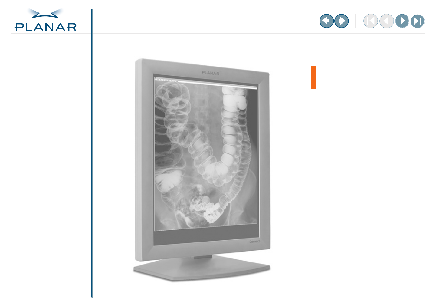
The Dome C3 display is designed for viewing medical X-ray images.
Safety precautions
External equipment intended for connection to signal input, signal output, or other
connectors, must comply with the relevant IEC standard (EN/IEC 60601-1 series for
medical electrical equipment). In addition, all such combinations (systems) must comply
with the standard IEC 60601-1-1,
complying to IEC 60601 must be kept outside the patient environment, as defined in
the standard as at least 1.5 meters from the patient or the patient support.
Any person who connects external equipment to signal input, signal output, or other
connectors has formed a system and is therefore responsible for the system to comply
with the requirements of IEC 60601-1-1. If in doubt, speak with a qualified technician.
To prevent fire or injury
•
Replace the power supply or cables if damaged.
Use only the appropriate power source indicated in this guide or listed on the display.
•
•
Activate the Dome CXtra Backlight Saver service (the preferred method) or
the DPMS energy saver when the display is idle for extended periods.
•
Do not plug the power supply into an overloaded AC outlet or extension cord.
Overloaded AC outlets and cords can result in electric shock or fire.
Do not drop or push objects into the display case. Internal components contain
•
high voltage.
Unplug the power cord from the wall outlet during thunderstorms.
•
•
Do not place magnetic devices, such as magnets or motors, near the display.
Dome C3 Display
Safety requirements for medical electrical systems
. Equipment not
Safety tips
Never open the Dome C3 display
•
case, even when the power is off.
Dangerous voltage inside may
cause electric shock or death.
•
To avoid damage to the Dome C3
display, use the grounded power
supply and video cable supplied
by Planar, or use certified
replacements.
Be sure the Dome C3 display is
•
electrically grounded. You must
connect the third grounding
pin on the US power cord to
a grounded outlet. The European
power cord does not have a third
grounding pin, but it still must be
plugged into a grounded outlet.
If you cannot insert the plug into
•
the outlet you plan to use, have
a licensed electrician replace the
outlet with a properly grounded
outlet. If your power cord
connects directly into the
computer, make sure the
computer is grounded.
•
Take appropriate measures to
keep the Dome C3 display dry
if it is within a surgical system.
The display lacks protection
against liquids or spills.
viii
Page 9
QUICK LINKS
Contents
Index
Regulatory Compliance
Product Information
Warranty
GETTING STARTED
About the Display
Package Contents
Identify Components
Position Display
Desk Stand Features
INSTALLING THE DISPLAY
Set DIP Switch
Install Display Controller
Connect Video and Power
Install Display Driver
Change Display Properties
Dome CXtra Software
APPENDIXES
Troubleshooting
Specifications
LED Status Lights
Single Desktop
USB Connection
Component Removal
Power Management
Palette Options
To set up the display properly
•
Allow the display to warm up to room temperature before turning it on, particularly if
the unit is cold from shipping or storage.
•
Avoid sudden temperature changes. Sudden changes may cause condensation that
can damage the display.
Turn off your computer, but leave it plugged into a grounded outlet.
•
•
Secure the display properly onto a standard VESA 100-mm mounting unit if you elect not
to use the desk stand.
•
Do not step on or place anything on top of the power cord.
Do not set up the display near strong light sources.
•
•
Do not block the vents on the back of the display or install the display in a built-in
enclosure. Blocked vents cause excessive heat to build up inside the display,
increasing risk of fire.
•
Do not expose the display to water or excessive moisture.
Do not place the display near a heat source.
•
•
Do not hang anything from the display.
•
Use the display only in an indoor setting.
To disconnect the power supply properly
First, turn off your computer and other connected devices. Then unplug
the power supply from the display or wall outlet.
Dome C3 Display
Reasons to disconnect power
Power cord is damaged.
•
Liquid spills inside the
•
display case.
Display is dropped or case
•
is damaged.
Display needs service or repair.
•
•
Display or case needs cleaning.
ix
Page 10
QUICK LINKS
Contents
Index
Regulatory Compliance
Product Information
Warranty
GETTING STARTED
About the Display
Package Contents
Identify Components
Position Display
Desk Stand Features
INSTALLING THE DISPLAY
Set DIP Switch
Install Display Controller
Connect Video and Power
Install Display Driver
Change Display Properties
Dome CXtra Software
APPENDIXES
Troubleshooting
Specifications
LED Status Lights
Single Desktop
USB Connection
Component Removal
Power Management
Palette Options
To clean the LCD screen
1
Unplug the power supply.
2
Dampen a clean, soft nonabrasive cloth with isopropyl alcohol.
Wipe the screen
3
4
Dry the screen with a clean, soft nonabrasive cloth to remove any residue.
gently
.
Shipping/storing the display
Keep the display in its shipping container until installation. Return the display to its
original container whenever you need to store the unit, move it to another location, or
return it for repair.
Before returning the display to the container for shipping or storing, do the following:
Swivel the display panel in portrait mode.
•
•
Push the panel down to the lowest position.
Use the stand lock to anchor the panel.
•
.Always transport the Dome C3i display in its original container. The packaging supplied
by the manufacturer protects the display from damage while it is in transit.
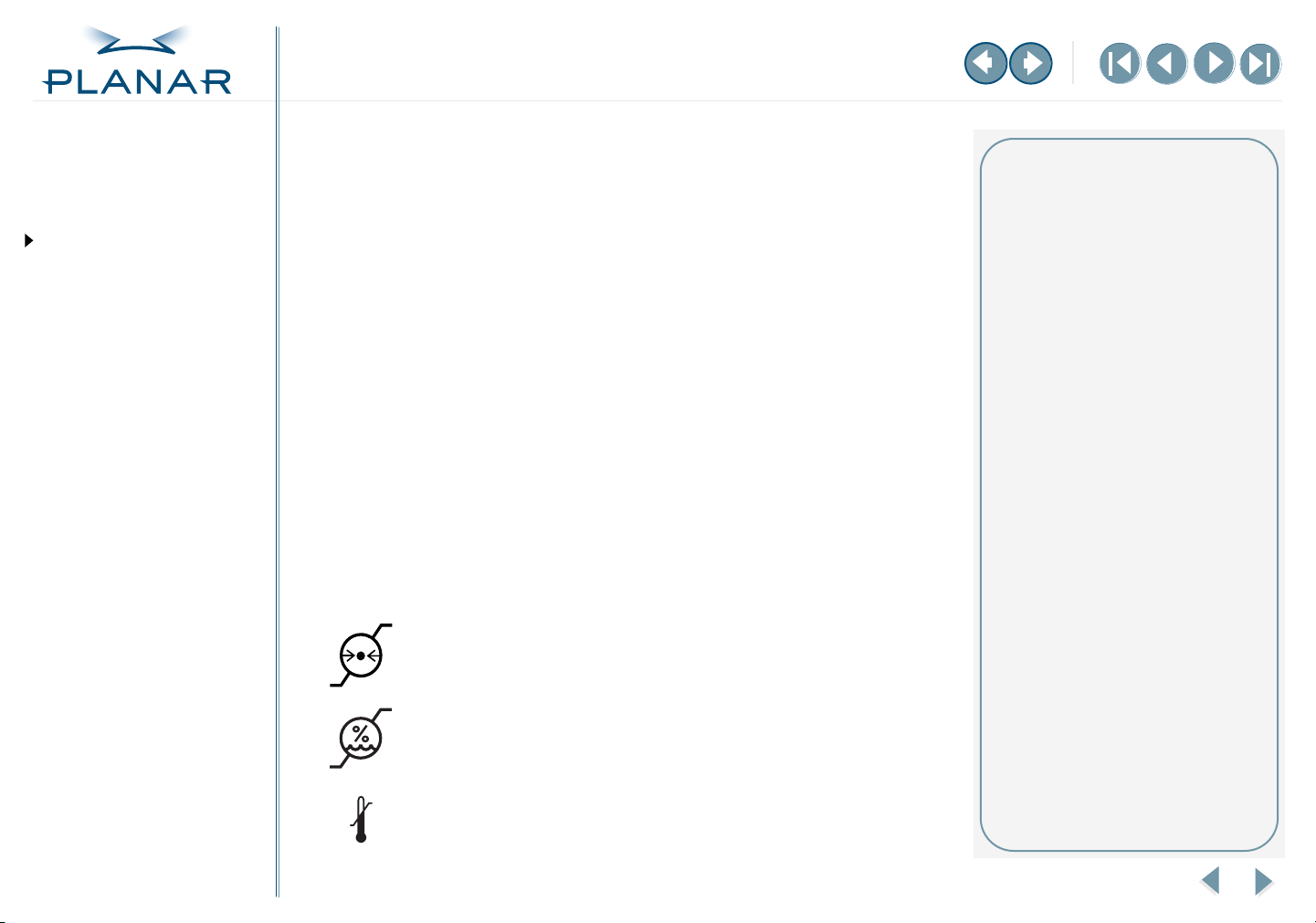
Symbol explanations
The following symbols may appear on the product or product packaging.
Barometric pressure
Relative humidity
Temperature
Dome C3 Display
Maintenance tips
Use a clean, lint-free, absorbent
•
cotton cloth to clear off any
residual glue from removal of
the protective film.
•
Use a clean, lint-free, absorbent
cotton cloth to remove surface
dust. Apply light pressure to
remove the dust.
•
Dampen a clean cloth with
a small amount of isopropyl
alcohol to remove glue or dust
if the screen is still not clean. Use
a clean, dry cloth to completely
remove the alcohol residue.
Do not use chemically treated
•
dust cloths on the display case or
LCD screen.
Do not use acetone, toluene, or
•
harsh solvents. They can damage
the polarizer and display case.
Do not saturate the cleaning
•
cloth with alcohol. The alcohol
may seep into the display case
and collect in the enclosure.
•
Do not allow water or other
stains to stand on the unit.
Wipe these off immediately to
prevent damage to the display
case and screen.
x
Page 11
QUICK LINKS
Contents
Index
Regulatory Compliance
Product Information
Warranty
GETTING STARTED
About the Display
Package Contents
Identify Components
Position Display
Desk Stand Features
INSTALLING THE DISPLAY
Set DIP Switch
Install Display Controller
Connect Video and Power
Install Display Driver
Change Display Properties
Dome CXtra Software
APPENDIXES
Troubleshooting
Specifications
LED Status Lights
Single Desktop
USB Connection
Component Removal
Power Management
Palette Options
About the Dome C3 Display
The Dome C3 display system consists of a 528-mm (20.8-in.) TFT LCD panel and
a DX display controller and driver. The display’s thin film transistors (TFTs), in
a transmissive-type display, use an integrated cold cathode fluorescent tube (CCFT)
backlight system.
The display is designed for 3-megapixel (1536 x 2048) grayscale medical imaging in
diagnostic settings, in either portrait or landscape orientation. It comes fully tuned
with gamma correction that complies with the DICOM Part 14 Standard. An alldigital design enables the display to produce the sharp, crisp images critical to
softcopy medical viewing. Unwanted analog display image artifacts, such as noise,
jitter, ghosting, and image smearing are eliminated.
The Dome C3 display is available as a color or grayscale panel. Each model offers
the following key features. See the specification for more information.
•
3061 distinct shades of gray
•
AMLCD technology for consistent image quality
•
Exceptional contrast ratio for viewing images in well-lit areas
• Accelerated hardware rotation for viewing images in portrait or landscape mode
• Calibrated to DICOM response curve
• Automated calibration and backlight stabilization through RightLight technology
The Dome CXtra™ software enhances the functionality of the Dome C3 display.
CXtra provides a range of value-added services, such as DICOM calibration,
error reporting, and backlight saver. Refer to the CXtra 3.0 User’s Guide for
more information.
Before installing the display system, review the safety and installation precautions.
Once your display system is in operation, follow the guidelines for cleaning and
servicing your unit.
Dome C3 Display
Systems requirements
Computer system
PCI slot per board
50 MB hard disk space
256 MB RAM
CD-ROM drive
Operating system
Windows XP or Windows 2000
1
Page 12
QUICK LINKS
Contents
Index
Regulatory Compliance
Product Information
Warranty
GETTING STARTED
About the Display
Package Contents
Identify Components
Position Display
Desk Stand Features
INSTALLING THE DISPLAY
Set DIP Switch
Install Display Controller
Connect Video and Power
Install Display Driver
Change Display Properties
Dome CXtra Software
APPENDIXES
Troubleshooting
Specifications
LED Status Lights
Single Desktop
USB Connection
Component Removal
Power Management
Palette Options
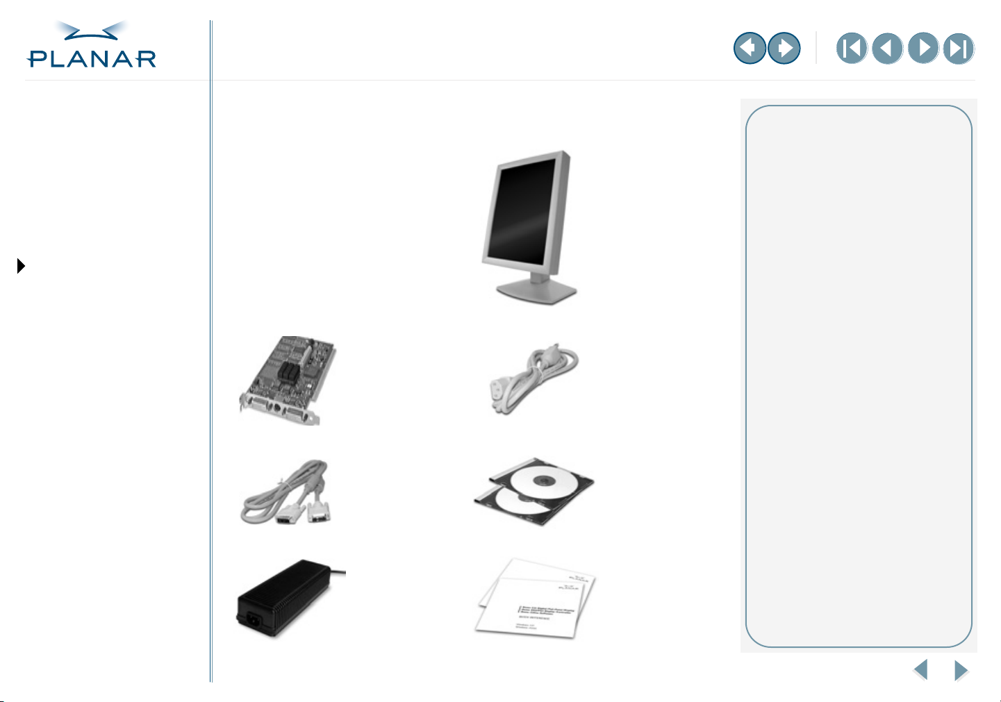
Package Contents
The Dome C3 display system contains the
items shown here. Speak with your sales
rep if any item is missing or damaged.
DX display
controller
DVI video cable
DC power adapter
Dome C3 Display
Dome C3 LCD
panel mounted
on desk stand
AC power cord
CD-ROMs with
display driver and
Dome CXtra
software
Quick references
for Dome C3
display and
Dome CXtra
software
Unpacking and handling tips
The Dome C3 display is a precision
instrument that requires proper care
to maintain product operation and
adherence to specification.
Unpack the display and components
carefully. Improper handling may
damage or break the LCD glass.
• Use both hands to grasp the
display case when lifting it from
the shipping carton, but avoid
touching the screen.
• Do not touch the polarizer with
foreign objects.
• Do not touch the polarizer with
bare fingers. Some cosmetics are
detrimental to the polarizer, and
skin oils are difficult to remove.
• Avoid sudden temperature
change as this may cause
condensation, which damages
the display.
• Do not subject the unit to strong
light sources.
• Do not remove the back cover or
disassemble the display. There
are no user-serviceable parts.
2
Page 13
QUICK LINKS
Contents
Index
Regulatory Compliance
Product Information
Warranty
GETTING STARTED
About the Display
Package Contents
Identify Components
Position Display
Desk Stand Features
INSTALLING THE DISPLAY
Set DIP Switch
Install Display Controller
Connect Video and Power
Install Display Driver
Change Display Properties
Dome CXtra Software
APPENDIXES
Troubleshooting
Specifications
LED Status Lights
Single Desktop
USB Connection
Component Removal
Power Management
Palette Options
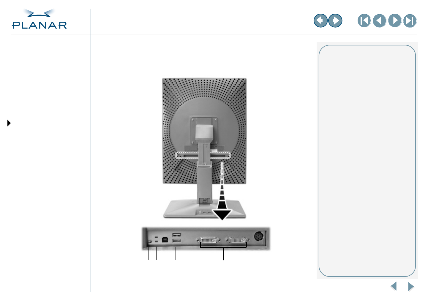
Identify the Components
Review this illustration of the back panel to identify controls and ports on
the display unit.
Dome C3 Display
3
2
1
4
5
6
Controls and connector ports
1 Reset button. Restores the
display configuration to its
default setting.
2 LED status lights. Provides
information about the status of
the display. See page 19 for
more information.
3 USB B (upstream) port
4 USB A (downstream) ports
5 DVI connectors. Drive the data
to the display.
6 8-pin DIN connector. Drives
power to the display.
3
Page 14
QUICK LINKS
Contents
Index
Regulatory Compliance
Product Information
Warranty
GETTING STARTED
About the Display
Package Contents
Identify Components
Position Display
Desk Stand Features
INSTALLING THE DISPLAY
Set DIP Switch
Install Display Controller
Connect Video and Power
Install Display Driver
Change Display Properties
Dome CXtra Software
APPENDIXES
Troubleshooting
Specifications
LED Status Lights
Single Desktop
USB Connection
Component Removal
Power Management
Palette Options
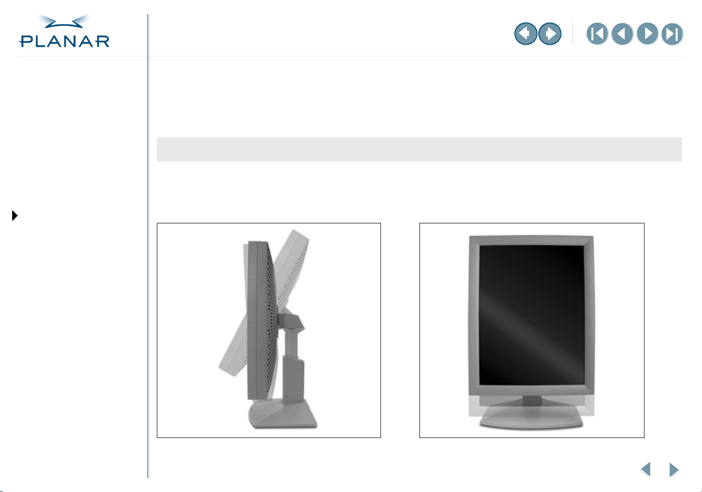
Position the Display
You can adjust the tilt, height, viewing angle, and orientation of the display to maintain an ergonomic and comfortable viewing
position. Before you unpack the display, select a suitable workspace for the display. You need a stable, level, and clean surface
near a wall outlet.
Tilt range Height range
Adjust the tilt angle of the display so that the screen faces
slightly downward from your angle of view.
Dome C3 Display
Unfasten the stand lock at the top of the desk stand (slide it
to the left) then raise or lower the panel to adjust the height.
Your eyes should be level with the top of the display cabinet
so that you look downward to read the screen contents.
4
Page 15
QUICK LINKS
Contents
Index
Regulatory Compliance
Product Information
Warranty
GETTING STARTED
About the Display
Package Contents
Identify Components
Position Display
Desk Stand Features
INSTALLING THE DISPLAY
Set DIP Switch
Install Display Controller
Connect Video and Power
Install Display Driver
Change Display Properties
Dome CXtra Software
APPENDIXES
Troubleshooting
Specifications
LED Status Lights
Single Desktop
USB Connection
Component Removal
Power Management
Palette Options
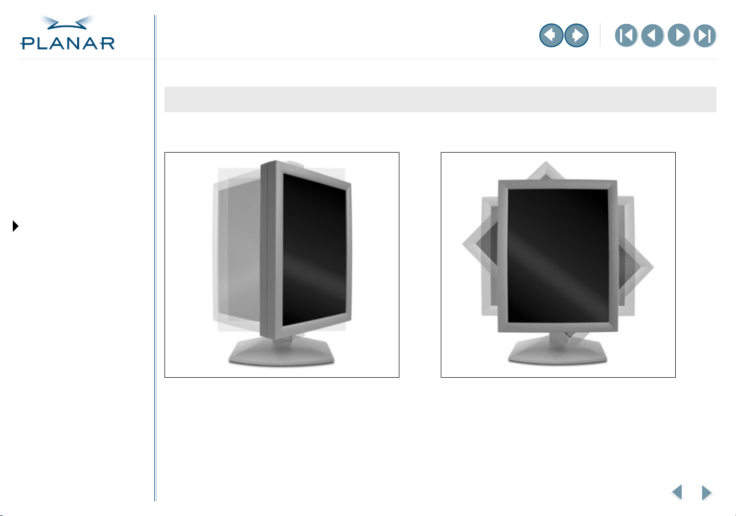
Viewing angle Orientation mode
Swivel the display panel from side to side to adjust the
viewing angle.
Dome C3 Display
Use both hands to turn the display 90 degrees clockwise to
rotate the display between portrait and landscape modes.
5
Page 16

QUICK LINKS
Contents
Index
Regulatory Compliance
Product Information
Warranty
Desk Stand Features
Unfasten the stand lock to adjust display height. Remove the stand cover to thread the power cord and DVI cable connections to
the display. To activate the USB hub function, the display must be connected to a USB-compliant computer or another hub with
a USB cable. Even if the display is in power-saving mode, the USB devices function when they are connected to the USB ports
(both upstream and downstream) of the display.
GETTING STARTED
About the Display
Package Contents
Identify Components
Position Display
Desk Stand Features
INSTALLING THE DISPLAY
Set DIP Switch
Install Display Controller
Connect Video and Power
Install Display Driver
Change Display Properties
Dome CXtra Software
APPENDIXES
Troubleshooting
Specifications
LED Status Lights
Single Desktop
USB Connection
Component Removal
Power Management
Palette Options
Stand lock Stand cover release USB hub
Move the stand lock lever to the left to
adjust the height of the display.
Dome C3 Display
Press the PUSH button at the bottom
of the desk stand and pull the stand
cover down and out to remove it.
Use the integrated, self-powered
USB hub to attach USB devices to the
display rather than to the computer.
6
Page 17

QUICK LINKS
Contents
Index
Regulatory Compliance
Product Information
Warranty
GETTING STARTED
About the Display
Package Contents
Identify Components
Position Display
Desk Stand Features
INSTALLING THE DISPLAY
Set DIP Switch
Install Display Controller
Connect Video and Power
Install Display Driver
Change Display Properties
Dome CXtra Software
APPENDIXES
Troubleshooting
Specifications
LED Status Lights
Single Desktop
USB Connection
Component Removal
Power Management
Palette Options
Set the DIP Switch
To enable VGA mode on the DX display controller, slide switch 1 on the DIP switch
into the ON position. Enable VGA on only one board when you install multiple
DX display controllers.
Disable VGA on all DX display controller if you are using a separate VGA card.
For single desktop mode, slide switch 3 into the ON position.
Dome C3 Display
Warning
If you leave the computer turned
on, you could get an electric shock
and cause damage to the system
components.
Remove the DX display controller
slowly from its package and staticshielding bag to prevent an
electrostatic discharge.
Static electricity can damage the
controller. When touching the board
or parts of the motherboard, take
these precautions:
• Wear an antistatic wrist strap.
• Discharge your body’s static
electricity repeatedly by
touching the power supply
or the metal surface of the
computer chassis.
7
Page 18

QUICK LINKS
Contents
Index
Regulatory Compliance
Product Information
Warranty
Install the Display Controller
Before you begin, choose a well-ventilated location with an adequate amount of space. Excessive heat cannot
dissipate when display vents are blocked. Make sure a grounded AC outlet is within easy reach.
When installing multiple DX display controllers, install all boards before you install the display driver.
Turn your computer off. Leave the power cord plugged into the grounded outlet.
GETTING STARTED
About the Display
Package Contents
Identify Components
Position Display
Desk Stand Features
INSTALLING THE DISPLAY
Set DIP Switch
Install Display Controller
Connect Video and Power
Install Display Driver
Change Display Properties
Dome CXtra Software
APPENDIXES
Troubleshooting
Specifications
LED Status Lights
Single Desktop
USB Connection
Component Removal
Power Management
Palette Options
To install the display controller
1 Remove the blank bracket from an available PCI slot. 2 Insert the display controller into the slot, align the
connector pins, and press the board down until it is
firmly seated. Secure the mounting bracket.
Dome C3 Display
8
Page 19

QUICK LINKS
Contents
Index
Regulatory Compliance
Product Information
Warranty
GETTING STARTED
About the Display
Package Contents
Identify Components
Position Display
Desk Stand Features
INSTALLING THE DISPLAY
Set DIP Switch
Install Display Controller
Connect Video and Power
Install Display Driver
Change Display Properties
Dome CXtra Software
APPENDIXES
Troubleshooting
Specifications
LED Status Lights
Single Desktop
USB Connection
Component Removal
Power Management
Palette Options
Connect Video Cable and Power Supply
Turn your computer off. Leave the power cord plugged into the grounded outlet.
Use the Dome C3 display with the power supply and video cable shipped. The
universal external 12V DC power supply is the Ault MW122RA1223F02.
To connect the display
1 Plug one end of the DVI cable into the video port on the interface plate.
Secure the connection.
2 Plug the power cord into the power input port on the interface plate.
3 Plug the other end of the DVI cable into the Video 1 port on the installed
DX display controller. Secure the connection.
4 Plug the other end of the power cord into the power supply.
5 Plug the power supply cord into a grounded AC outlet.
Dome C3 Display
Installation tips
Easy access to ports
For displays mounted on a desk
stand, rotate the LCD panel from
portrait to landscape for easy
access to the ports.
Threading cables
Thread the DVI cable and power
cord through the back of the stand.
Make sure the cable and cord run
through the notches. To reattach the
stand cover, align the hooks with the
slots on the stand. Press the cover
into place. A click sound signals
a secure connection.
Restarting
Turn on your display before you turn
on your computer. Failing to do so
could damage the display.
Multiple displays
Connect the first display of a twoheaded system, or the only display
of a one-headed system, to the
Video 1 port. Connect all displays to
the DX display controller before you
turn on the computer system to
install the driver. The driver can
then detect all displays.
Using two displays allows you to
view two images simultaneously or
one image across both displays.
9
Page 20

QUICK LINKS
Contents
Index
Regulatory Compliance
Product Information
Warranty
GETTING STARTED
About the Display
Package Contents
Identify Components
Position Display
Desk Stand Features
INSTALLING THE DISPLAY
Set DIP Switch
Install Display Controller
Connect Video and Power
Install Display Driver
Change Display Properties
Dome CXtra Software
APPENDIXES
Troubleshooting
Specifications
LED Status Lights
Single Desktop
USB Connection
Component Removal
Power Management
Palette Options
Install the Display Driver
Before you install the driver, remove any previously installed display driver for the
DX display controller from your computer system. Follow the procedure shown in
the sidebar.
Use the following procedures to install the display driver on Windows XP and
Windows 2000 systems.
To install the driver
1 Log on with administrator privileges. The InstallShield Wizard reports
new hardware.
2 Click Cancel. You must run Setup.exe to install the driver.
3 Insert the W2KDXPCI CD and open the CD folder.
4 Double-click Setup.exe.
5 Click Next to proceed through the installation and start copying files.
6 Click Yes on the Digital Signature Not Found dialog box for each display that
you install. (On Windows XP systems, the Hardware Installation dialog box is
equivalent. Click Continue Anyway to proceed.)
7 Select Yes, I want to restart my computer now, and click Finish.
To enable the display
1 Log on with administrator privileges.
2 Right-click the desktop. Select Properties > Settings.
3 Select the display icon.
4 Select Extend my Windows desktop onto this monitor. Click Apply.
5 Click OK.
Dome C3 Display
Removing an existing driver
If necessary, uninstall the 63-WINDX
driver for the DX display controller
before you install the 63-W2KDXPCI
driver.
To remove the 63-WINDX driver
1 Log on with administrator
privileges.
2 Insert the WINDX CD and
open the CD folder.
3 Browse to the Win2k\DXpci
directory.
4 Double-click Setup.exe.
5 Select Remove and click Next.
6 Click OK to confirm uninstall.
7 Select Yes, I want to restart my
computer now, and click Finish.
10
Page 21

QUICK LINKS
Contents
Index
Regulatory Compliance
Product Information
Warranty
GETTING STARTED
About the Display
Package Contents
Identify Components
Position Display
Desk Stand Features
INSTALLING THE DISPLAY
Set DIP Switch
Install Display Controller
Connect Video and Power
Install Display Driver
Change Display Properties
Dome CXtra Software
APPENDIXES
Troubleshooting
Specifications
LED Status Lights
Single Desktop
USB Connection
Component Removal
Power Management
Palette Options
Change the Display Properties
You can change the display properties, such as resolution, palette options, and
brightness, using the Dome tab after the Dome C3 display is attached to the
Windows desktop. Otherwise, use Properties > Settings tab.
To determine screen assignments
Click Identify in the Settings tab to match screens to display controllers.
To set the resolution
Use the Resolution field on the Dome tab to set the resolution to portrait,
landscape, or single desktop. When you set the resolution for one display of
a dual-headed DX display controller, the second display assumes the
same resolution.
1 Log on with administrator privileges.
2 Right-click the desktop. Select Properties > Settings.
3 Select Default Monitor and Dome DX/PCI Properties from the Display list.
4 Check the selection box for Extend my Windows desktop onto this monitor.
5 Select Advanced > Dome.
6 Choose a resolution and palette option. Click Apply.
7 Click OK until you return to the desktop.
To set palette options
For more information on palette options, see “Palette Options” on page 27.
To set brightness
In the Brightness field of the DOME tab, slide the scroll box left or right, or use
the left and right arrows, to set brightness for each flat panel. (The default
brightness is 100%.) Click OK.
Dome C3 Display
Screen assignments
Windows 2000 renumbers and
reassigns screens as you add them
to the configuration. Set resolutions
or preferences only after all display
controller and screens are installed.
Restart your system to make sure the
screen assignments are retained.
Resolutions and palettes
Set display properties on the Dome
C3 display using the resolutions and
palette options listed below. Note
that single desktop requires a dual
display system.
Resolutions available
1536 x 2048 portrait
2048 x 1536 landscape
3072 x 2048 single desktop, portrait
4096 x 1536 single desktop, landscape
Palette options
C3 gray display:
Dynamic gray
Nonlinear gray
Static gray
True color
C3 color display:
Color
True color
11
Page 22

QUICK LINKS
Contents
Index
Regulatory Compliance
Product Information
Warranty
GETTING STARTED
About the Display
Package Contents
Identify Components
Position Display
Desk Stand Features
INSTALLING THE DISPLAY
Set DIP Switch
Install Display Controller
Connect Video and Power
Install Display Driver
Change Display Properties
Dome CXtra Software
APPENDIXES
Troubleshooting
Specifications
LED Status Lights
Single Desktop
USB Connection
Component Removal
Power Management
Palette Options
To set driver options
Beware that the Disable DirectDraw driver option has specific conditions which may
affect your display.
In the Driver Options field of the Dome tab, select Disable DirectDraw.
Click Apply or OK.
To get information
Information about the flat panel, display controller, and driver appears on the lower
half of the Dome tab.
Panel information includes panel type, serial number, backlight usage, and
onboard temperature (in degrees Celsius). The temperature reading of a panel
is given when you first open the panel and if you later select it. The revision numbers
of the firmware and microcontrollers are also included. General information includes
display controller type, driver version, and library version.
Dome C3 Display
12
Page 23

QUICK LINKS
Contents
Index
Regulatory Compliance
Product Information
Warranty
GETTING STARTED
About the Display
Package Contents
Identify Components
Position Display
Desk Stand Features
INSTALLING THE DISPLAY
Set DIP Switch
Install Display Controller
Connect Video and Power
Install Display Driver
Change Display Properties
Dome CXtra Software
APPENDIXES
Troubleshooting
Specifications
LED Status Lights
Single Desktop
USB Connection
Component Removal
Power Management
Palette Options
Enhancements with Dome CXtra Software
The Dome CXtra™ software enhances the functionality of the Dome C3 display for
viewing medical images in diagnostic settings. The CX Edition 4.0 for Dome CX
displays comes in two volumes: the base package ships with the display; the
validation package is sold separately.
The advantages of Dome CXtra includes consistent grayscale presentation of
images, as a result of conformance with the DICOM Grayscale Standard display
function. Specifically, the Dome C3 display is fully calibrated to the DICOM response
curve. It uses an embedded RightLight™ sensor to provide continuous luminance
stability, guaranteeing consistent image quality and adherence to DICOM standards.
This sensor works with the digital interface board that is built into the back of
the Dome C3 display.
Dome CXtra base services allow you to monitor and stabilize display backlights,
schedule the backlight saver, and retrieve information on CXtra events and
errors conditions.
With validation services, you can run display acceptance tests, including
the recommendations of the American Association of Physicists in Medicine
Task Group 18 and the DIN test standards. You can also monitor and maintain
your Dome C3 display locally or from a remote location using any SNMP
console application.
For more information, visit www.planar.com.
Dome C3 Display
CX Edition 4.0
Base package, included with display:
• Reporting – Access service info,
view events and history, and check
events related to error conditions.
• RightLight – Stabilize display
backlights and maintain DICOM
conformance and desired white
level across displays.
• Backlight saver – Schedule sleep
for the display backlights.
• Privilege – Limit users who can
change display parameters.
Validation package, sold separately:
• AAPM TG18 Test – Use AAPM TG 18
recommendations to test displays.
• DIN acceptance – Perform the
German standard test to measure
display performance.
• QuickSwitch – Toggle between
portrait and landscape modes.
• Test patterns – View test patterns
that show the display image quality.
• Enterprise management – Manage
displays remotely using any SNMP
console application, or locally.
13
Page 24

QUICK LINKS
Contents
Index
Regulatory Compliance
Product Information
Warranty
GETTING STARTED
About the Display
Package Contents
Identify Components
Position Display
Desk Stand Features
INSTALLING THE DISPLAY
Set DIP Switch
Install Display Controller
Connect Video and Power
Install Display Driver
Change Display Properties
Dome CXtra Software
Troubleshooting
Problem
No image appears on
the screen
Power LED is amber Display is in DPMS mode. Turn off DPMS mode.
“Check video cable” message Video cable is not securely fastened. Turn off computer. Check and secure connection.
Possible cause Solution
Computer is not powered on. Turn on computer.
Power cord is not securely connected. Tighten power cord connection and turn on computer.
Video cable connected incorrectly. Make sure the first display of a dual-headed system or the
only display of a single-headed system is connected to the
Video 1 port on the DX display controller. (See page 8.)
No active signal coming from computer. Turn off computer and secure connections.
Signal cable is not fastened securely. Turn off computer and secure connections.
Computer video signal is not VESA DPMS
standard.
Use a VESA DPMS-compliant computer or video controller.
Check computer power and graphics adapter configuration.
APPENDIXES
Troubleshooting
Specifications
LED Status Lights
Single Desktop
USB Connection
Component Removal
Power Management
Palette Options
VGA not enabled Incorrect DIP switch settings. You may need to remove the DX display controller to check
the DIP switch settings. You can enable VGA on the DX
display controller or use a separate VGA card. See page 7
for the correct switch positions to enable or disable VGA,
depending on your system.
(cont.)
Dome C3 Display
14
Page 25

QUICK LINKS
Contents
Index
Regulatory Compliance
Product Information
Warranty
GETTING STARTED
About the Display
Package Contents
Identify Components
Position Display
Desk Stand Features
INSTALLING THE DISPLAY
Set DIP Switch
Install Display Controller
Connect Video and Power
Install Display Driver
Change Display Properties
Dome CXtra Software
APPENDIXES
Troubleshooting
Specifications
LED Status Lights
Single Desktop
USB Connection
Component Removal
Power Management
Palette Options
Problem Possible cause Solution
Unsigned driver cannot be
loaded message
Conflict with driver versions A previous version of the display driver is still
Dome C3 Display
To allow installation of Dome drivers, set
the HKCU\Software\Policies\Microsoft\
Windows NT\Driver Signing key.
installed on the computer system.
The installation CD contains a file older than
the one currently on your system.
To allow installation of Dome drivers, set the
HKCU\Software\Policies\Microsoft\Windows NT\
Driver Signing key.
To install the driver:
Select Start > Settings > Control Panel > System.
1
The System Properties dialog box appears.
Select Hardware > Driver Signing in the Device Manager
2
section.
Select either Ignore or Warn to allow installation of
3
the Dome driver and other unsigned drivers.
•If you select Ignore, the installation program ignores
•If you select Warn, the message Digital Signature Not
Remove any existing Dome display driver before you install
a more recent version.
The Confirm File Replace dialog box appears if the
installation CD contains a file older than the one currently
on your system. Click No to the question Overwrite the
newer file? or click No to All.
the lack of a valid Catalog file with a digital signature.
Found appears and prompts you to continue or cancel.
15
Page 26
QUICK LINKS
Contents
Index
Regulatory Compliance
Product Information
Warranty
GETTING STARTED
About the Display
Package Contents
Identify Components
Position Display
Desk Stand Features
INSTALLING THE DISPLAY
Set DIP Switch
Install Display Controller
Connect Video and Power
Install Display Driver
Change Display Properties
Dome CXtra Software
APPENDIXES
Troubleshooting
Specifications
LED Status Lights
Single Desktop
USB Connection
Component Removal
Power Management
Palette Options
Display Specifications
Display Category Characteristic Item Specification
Screen Screen size diagonal 52.8 cm (20.8 in.)
Resolution 1536 x 2048 pixels (portrait); 2048 x 1536 pixels (landscape)
Pixel pitch 0.207 mm x 0.207 mm
Pixel arrangement Subpixel vertical stripe
Active area (mm) 423.9 (H) x 318.0 (V )
Number of colors supported C3 Color – 16.7 million true color (8 bits/RGB); 8-bit pseudocolor (256 colors)
C3 Gray – 3061 shades of gray – programmable gamma
Refresh rate 60 Hz
Contrast ratio 600:1 (typical)
Brightness C3 Color – 70 fL, or 235 cd/m2 (typical)
C3 Gray – 233 fL, or 800 cd/m2 (typical)
Pixel rise/fall time 50 ms
Viewing angle 170° (± 85°) horizontal/vertical
Interface Digital Video In 2 DVI single-channel digital connectors
Display control - brightness/contrast DDC2B+
Display identification EDID read using DDC2B+
USB hub Universal Serial Bus (USB) Rev. 1.1: 1 uplink B port; 2 downlink A ports
Monitor status Dual stack tricolor LEDs on back panel
Input formats Landscape orientation 2048 x 1536 (8- and 24-bit per pixel)
Portrait orientation 1536 x 2048 (8- and 24-bit per pixel) with automatic hardware rotate
VGA™/XGA 640 x 480 to 1024 x 768 pixels displayed in both landscape and portrait rotation
Screen type AMLCD (active-matrix liquid crystal display)
Physical Display size (without stand) 485.78 mm x 381 mm x 101.6 mm (19.125 in. x 15 in. x 4 in.)
Display weight (without stand) 6.35 kg (14 lb.)
Mounting options 100-mm VESA mounting standard
Power requirements Input voltage +12 V ±10%
Power consumption 90 Watts maximum
Dome C3 Display
16
Page 27

QUICK LINKS
Contents
Index
Regulatory Compliance
Product Information
Warranty
GETTING STARTED
About the Display
Package Contents
Identify Components
Position Display
Desk Stand Features
INSTALLING THE DISPLAY
Set DIP Switch
Install Display Controller
Connect Video and Power
Install Display Driver
Change Display Properties
Dome CXtra Software
APPENDIXES
Troubleshooting
Specifications
LED Status Lights
Single Desktop
USB Connection
Component Removal
Power Management
Palette Options
Power Supply
Power Supply Category Characteristic Item Specification
Power input requirements Voltage selection Auto-ranging
Voltage 100 – 240V AC
Current 2.0 A
Frequency 50 to 60 Hz
Power output requirements Voltage 12 V DC ±5%
Current 10.0 A (120 W)
Physical Size 228.6 mm x 76.2 mm x 50.8 mm (9 in x 3 in x 2 in)
Weight 1.3 kg (2.75 lb)
Reliability
Characteristic item Specification
Display plus backlight MTBF 50,000 hours with 50% duty cycle on backlight
Backlight MTBF 30,000 hours to 50% brightness with backlight on continuously
Environment
Characteristic item Specification
EMI shielding No emission of low-level radiation
Temperature operating 10° to 40° C
storage -10° to 60° C
Humidity operating 20% to 80% Relative Humidity (non-condensing)
storage 5% to 90% Relative Humidity (non-condensing)
Dome C3 Display
17
Page 28

QUICK LINKS
Contents
Index
Regulatory Compliance
Product Information
Warranty
GETTING STARTED
About the Display
Package Contents
Identify Components
Position Display
Desk Stand Features
INSTALLING THE DISPLAY
Set DIP Switch
Install Display Controller
Connect Video and Power
Install Display Driver
Change Display Properties
Dome CXtra Software
APPENDIXES
Troubleshooting
Specifications
LED Status Lights
Single Desktop
USB Connection
Component Removal
Power Management
Palette Options
Video Modes
Resolutions expressed in pixels (W x H). Single desktop requires dual displays.
CX display Resolution option Orientation Palette option Bits per pixel
C3 gray 1536 x 2048
2048 x 1536
3072 x 2048
4096 x 1536
C3 color 1536 x 2048
2048 x 1536
3072 x 2048
4096 x 1536
C3 gray or
color
1536 x 2048
2048 x 1536
3072 x 2048
4096 x 1536
Portrait
Landscape
Portrait, single desktop
Landscape, single desktop
Portrait
Landscape
Portrait, single desktop
Landscape, single desktop
Portrait
Landscape
Portrait, single desktop
Landscape, single desktop
Dynamic gray
Nonlinear gray
Static gray
Color 8
True color 32
8
DVI 1.0 Interface
The Dome C3 display connects to the DX board via a DVI 1.0 interface. Power input is
12V ±5% (100 W). See details of the 8-pin DIN power connector to the right.
Dome C3 Display
DIN connector
Details of the 8-pin DIN connector.
VCC 8
VCC 7
VCC 6
VCC 5 3 GND
4 GND
1 GND
2 GND
18
Page 29

QUICK LINKS
Reset button (left) and LEDs on interface plate
LED B
LED A, top
Contents
Index
Regulatory Compliance
Product Information
Warranty
GETTING STARTED
About the Display
Package Contents
Identify Components
Position Display
Desk Stand Features
INSTALLING THE DISPLAY
Set DIP Switch
Install Display Controller
Connect Video and Power
Install Display Driver
Change Display Properties
Dome CXtra Software
APPENDIXES
Troubleshooting
Specifications
LED Status Lights
Single Desktop
USB Connection
Component Removal
Power Management
Palette Options
LED Status Lights
The two LEDs on the back panel provide information about the display.
• LED A describes the digital-link status between the DX display controller and the interface.
• LED B describes the display-panel status. it shows any faults currently in the panel.
Power-up sequence information from LED
LED A Action/Sequence LED B Description
Solid green Initial power-on Solid green One (1) second of solid green to verify
the green LED works.
Solid red One (1) second after power-on Solid red One (1) second of solid red to verify the
red LED works.
Solid yellow Two seconds after power-on Solid yellow One (1) second of solid yellow to verify
Flashing red Link working, unrecognized sync
Flashing yellow n seconds after power-on Flashing yellow Service fault was discovered during
Dome C3 Display
information
Flashing red Internal fatal fault was discovered during
the yellow LED works.
power-on self-test.
power-on self-test.
19
Page 30
QUICK LINKS
Contents
Index
Regulatory Compliance
Product Information
Warranty
LED A status information after initial power-on
LED Status Description
Solid green Fault
Flashing green Functional link – normal operation
GETTING STARTED
About the Display
Package Contents
Identify Components
Position Display
Desk Stand Features
INSTALLING THE DISPLAY
Set DIP Switch
Install Display Controller
Connect Video and Power
Install Display Driver
Change Display Properties
Dome CXtra Software
APPENDIXES
Troubleshooting
Specifications
LED Status Lights
Single Desktop
USB Connection
Component Removal
Power Management
Palette Options
Flashing red Link working, unrecognized sync information
Solid yellow Receiving DDC information
Alternating red/green No cable detected
LED B status information after initial power-on
LED Status Description
Solid green Fault
Flashing green Functional system – normal operation
Dome C3 Display
20
Page 31

QUICK LINKS
Contents
Index
Regulatory Compliance
Product Information
Warranty
GETTING STARTED
About the Display
Package Contents
Identify Components
Position Display
Desk Stand Features
INSTALLING THE DISPLAY
Set DIP Switch
Install Display Controller
Connect Video and Power
Install Display Driver
Change Display Properties
Dome CXtra Software
APPENDIXES
Troubleshooting
Specifications
LED Status Lights
Single Desktop
USB Connection
Component Removal
Power Management
Palette Options
Single Desktop
On Windows systems, the single desktop supports the Dome C3 display in portrait
mode only. From one DX display controller, you can run a single desktop across
two Dome C3 displays.
The procedures in this section show you how to complete the initial installation of
single desktop and how to change your system configuration to move from dualheaded display to single desktop.
On the DX display controller, switch 3 on DIP switch must be in the ON position for
each procedure. (See page 7.)
To set the display resolution
After you install the display controller and driver, use the Dome tab to set the
display resolution for single desktop.
1 Right-click the desktop, and select Properties > Settings.
The Settings tab appears.
2 Select Default Monitor and Dome DX/PCI from the Display list. Make sure
the box for Extend my Windows desktop onto this monitor is checked.
3 Select Advanced > Dome. (See page 22.)
4 In the resolution field, choose the resolution for single desktop, 3072 x 2048.
5 Click OK.
6 Go to step 7 of the procedure on page 11 to complete this operation.
Dome C3 Display
Using multiple displays
Each DX display controller can
support two Dome C3 displays in
portrait or landscape mode. Using
two displays, side by side, allows you
to view two images simultaneously
or one image across both displays.
To view one image across both
displays, use the single desktop
configuration.
21
Page 32

QUICK LINKS
Contents
Index
Regulatory Compliance
Product Information
Warranty
GETTING STARTED
About the Display
Package Contents
Identify Components
Position Display
Desk Stand Features
INSTALLING THE DISPLAY
Set DIP Switch
Install Display Controller
Connect Video and Power
Install Display Driver
Change Display Properties
Dome CXtra Software
APPENDIXES
Troubleshooting
Specifications
LED Status Lights
Single Desktop
USB Connection
Component Removal
Power Management
Palette Options
On the Dome tab, select
resolution 3072 x 2048 for
the single desktop
To change the configuration to single desktop
If you are working on a dual-headed display, you can use the following procedure
to change your hardware and software configuration to single desktop.
1 Use the InstallShield Wizard to uninstall the existing driver (dx.5.1.0.003
release and higher). See “To uninstall the driver” on page 25.
2 On the DIP switch, place switch 3 in the ON position. (See page 7.)
3 Reinstall the DX display controller. (See page 8.) Then attach both displays to
the controller. (See page 9.)
4 Power on the system, and run Setup.exe to install the driver. (See page 10.)
5 Set the display resolution. (See page 11).
Dome C3 Display
Safety precaution
Wear an antistatic wrist strap when
handling the board and display to
prevent electrostatic discharge.
22
Page 33

QUICK LINKS
Contents
Index
Regulatory Compliance
Product Information
Warranty
GETTING STARTED
About the Display
Package Contents
Identify Components
Position Display
Desk Stand Features
INSTALLING THE DISPLAY
Set DIP Switch
Install Display Controller
Connect Video and Power
Install Display Driver
Change Display Properties
Dome CXtra Software
APPENDIXES
Troubleshooting
Specifications
LED Status Lights
Single Desktop
USB Connection
Component Removal
Power Management
Palette Options
To get information
Open the Dome tab to retrieve information on the two displays you are using
to run single desktop. Information for both left and right panels appears at
the bottom of the Dome tab, as shown in this illustration. See page 12 for
more information.
Dome C3 Display
Restoring dual heads
To return to dual-headed display,
follow the procedure above but
place switch 3 on the DIP switch
in the OFF position. Then use the
procedures in “Change the Display
Properties” on page 11 to set the
display resolution.
23
Page 34

QUICK LINKS
Contents
Index
Regulatory Compliance
Product Information
Warranty
GETTING STARTED
About the Display
Package Contents
Identify Components
Position Display
Desk Stand Features
INSTALLING THE DISPLAY
Set DIP Switch
Install Display Controller
Connect Video and Power
Install Display Driver
Change Display Properties
Dome CXtra Software
APPENDIXES
Troubleshooting
Specifications
LED Status Lights
Single Desktop
USB Connection
Component Removal
Power Management
Palette Options
USB Connection
The display desk stand contains an integrated, self-powered USB hub that allows
you to attach USB devices (such as a keyboard or mouse) to the Dome C3 display
rather than to a computer.
To use the USB ports
1 Use a Type A-B USB cable to connect the USB B port on the desk stand to
the USB A port on your USB-compliant computer or other hub.
2 Connect USB-compliant peripherals to the USB A ports on the desk stand.
B
Dome C3 Display
A
Legend
USB A (downstream) port
A
USB B (upstream) port
B
USB tips
To activate the USB hub function,
connect the display to a USBcompliant computer or another
hub with the Type A-B USB cable.
Use USB devices connected to the
display even when the display is in
power-saving mode.
Use USB devices connected to the
display even when the display is
unplugged from the power source.
The USB hub on the desk stand is
powered by the computer.
24
Page 35
QUICK LINKS
Contents
Index
Regulatory Compliance
Product Information
Warranty
GETTING STARTED
About the Display
Package Contents
Identify Components
Position Display
Desk Stand Features
INSTALLING THE DISPLAY
Set DIP Switch
Install Display Controller
Connect Video and Power
Install Display Driver
Change Display Properties
Dome CXtra Software
APPENDIXES
Troubleshooting
Specifications
LED Status Lights
Single Desktop
USB Connection
Component Removal
Power Management
Palette Options
Display Driver and Controller Removal
Removing the DX display controller is a two-part process. Use the InstallShield
Wizard to uninstall the driver first. Then use the Device Manager to remove
the controller.
To uninstall the driver
1 Insert the WINDX CD, and browse to find the Win2k\DXpcidirectory.
2 Double-click Setup.exe. The Welcome dialog box appears.
3 Select Remove, and click Next.
4 Click OK to confirm uninstall.
5 Select Yes, I want to restart my computer now, and click Finish.
To remove the device
1 Right-click My Computer.
2 Select Properties and click Hardware then Device Manager.
3 Open Display Adapters.
4 Highlight the device you want to uninstall.
5 Press the <Delete> key or click the Delete icon, then click OK.
6 Shut down the computer and remove the display controller.
Dome C3 Display
Safety precaution
Wear an antistatic wrist strap when
handling the DX display controller to
prevent electrostatic discharge.
25
Page 36

QUICK LINKS
Contents
Index
Regulatory Compliance
Product Information
Warranty
GETTING STARTED
About the Display
Package Contents
Identify Components
Position Display
Desk Stand Features
INSTALLING THE DISPLAY
Set DIP Switch
Install Display Controller
Connect Video and Power
Install Display Driver
Change Display Properties
Dome CXtra Software
APPENDIXES
Troubleshooting
Specifications
LED Status Lights
Single Desktop
USB Connection
Component Removal
Power Management
Palette Options
Power Management
You have two ways to lower energy usage when the Dome C3 display is idle:
• Dome CXtra Backlight Saver service (preferred)
• DPMS (Display Power Management Signaling)
Activate the power saver when you anticipate periods of inactivity, such as at the
end of the work day. Once activated, Backlight Saver (or DPMS) automatically turns
the backlight off during the period of inactivity. Backlight Saver and DPMS both
extend the life of the backlight and reduce burn-in of images.
To activate DPMS, use the display with a computer that has power-saving circuitry.
Computers running the Windows XP or Windows 2000 operating system have this
feature built in.
The backlight lasts approximately 30,000 on-time hours.
Do not use both the Backlight Saver and DPMS.
Dome C3 Display
26
Page 37

QUICK LINKS
Contents
Index
Regulatory Compliance
Product Information
Warranty
GETTING STARTED
About the Display
Package Contents
Identify Components
Position Display
Desk Stand Features
INSTALLING THE DISPLAY
Set DIP Switch
Install Display Controller
Connect Video and Power
Install Display Driver
Change Display Properties
Dome CXtra Software
APPENDIXES
Troubleshooting
Specifications
LED Status Lights
Single Desktop
USB Connection
Component Removal
Power Management
Palette Options
Palette Options
The Dome DX display controller supports different palette options on
Windows systems.
In the Palette Options field of the Dome tab, use the pull-down menu to select
a palette. Then click Apply or OK.
Dome palette options must coordinate with the primary display. All flat panels
must be set to either palette devices or non-palette devices, as shown in this table.
Palette Device Non-Palette Device
• Dynamic gray • Nonlinear static gray
• Static gray
All Dome display controllers that support multiple displays also support differing
palette options on multiple screens attached to the same controller.
See the assignment of values on the grayscale palettes on page 28.
Dome C3 Display
27
Page 38

QUICK LINKS
Contents
Index
Regulatory Compliance
Product Information
Warranty
GETTING STARTED
About the Display
Package Contents
Identify Components
Position Display
Desk Stand Features
INSTALLING THE DISPLAY
Set DIP Switch
Install Display Controller
Connect Video and Power
Install Display Driver
Change Display Properties
Dome CXtra Software
APPENDIXES
Troubleshooting
Specifications
LED Status Lights
Single Desktop
USB Connection
Component Removal
Power Management
Palette Options
Assignment of values on the grayscale palettes
Palette options with multiple displays
The SelectPalette and RealizePalette functions in the Microsoft Developer’s
Network, or MSDN, work across all flat-panel displays if the primary panel is
palettized. The palettes of all palette-type devices are synchronized. If, however,
the primary panel is not palettized, the SelectPalette and RealizePalette functions
select the palette into the background, and palettized devices are not
synchronized.
Dome C3 Display
28
Page 39

QUICK LINKS
Contents
Index
Regulatory Compliance
Product Information
Warranty
Desktop icons
The palette specifications of the primary display determine how desktop icons are
drawn. For example, the desktop icons appear gray on a color screen if the primary
display is set to a gray palette.
The following table lists the palette options available on primary and secondary
displays. A check mark (✔) indicates the palette combination that works.
GETTING STARTED
About the Display
Package Contents
Identify Components
Position Display
Desk Stand Features
INSTALLING THE DISPLAY
Set DIP Switch
Install Display Controller
Connect Video and Power
Install Display Driver
Change Display Properties
Dome CXtra Software
APPENDIXES
Troubleshooting
Specifications
LED Status Lights
Single Desktop
USB Connection
Component Removal
Power Management
Palette Options
SECONDARY DISPLAY
PRIMARY DISPLAY
Dynamic gray ✔✔ ✔✔
Nonlinear static gray ✔✔
Static gray ✔✔
True color ✔✔✔✔
Pseudocolor ✔✔✔
Dynamic gray
Nonlinear
static gray Static gray True color Pseudocolor
Dynamic gray palette
The dynamic gray palette reserves the first and last 10 entries in the palette for the
Windows NT operating system, but you can manipulate the middle 236 entries.
Your application can create a 256-entry gray ramp in any 8-bit driver by calling the
Windows API function SetSystemPaletteUse(), but doing so causes all icons to be
redrawn in black and white.
The dynamic gray palette accommodates gray-mapped Windows colors for
the first and last 10 palette entries.
Dome C3 Display
29
Page 40

QUICK LINKS
Contents
Index
Regulatory Compliance
Product Information
Warranty
GETTING STARTED
About the Display
Package Contents
Identify Components
Position Display
Desk Stand Features
INSTALLING THE DISPLAY
Set DIP Switch
Install Display Controller
Connect Video and Power
Install Display Driver
Change Display Properties
Dome CXtra Software
APPENDIXES
Troubleshooting
Specifications
LED Status Lights
Single Desktop
USB Connection
Component Removal
Power Management
Palette Options
Nonlinear static gray palette
The nonlinear static gray palette sets the first and last 10 palette entries to graymapped Windows colors. The middle 236 entries are ramped in ascending order,
excluding the first and last 10 palette entries. Windows applications that use the
first and last 10 palette entries as Windows colors display correctly on the screen.
Although the nonlinear static gray palette provides correct colors for applications
using the Windows palette, colors display incorrectly if the application assumes
that a static palette is always ramped.
Static gray palette
The static gray palette provides 256 shades of gray in a static palette. This palette
does not reserve the first and last 10 palette entries for icons and other standard
Windows graphics, which frees the entire grayscale ramp for applications.
The static gray palette does not provide gray-mapped Windows colors for the first
and last 10 palette entries. Because the framebuffer assumes the Windows palette
is in use, applications that draw directly to the framebuffer display incorrectly.
For example, icons and button bitmaps may display in black and white.
Dome C3 Display
Note
Applications cannot set the
nonlinear static gray palette or
the static gray palette. They must
read the palette from the operating
system and use it when drawing
directly to the framebuffer.
Application colors display
incorrectly if the application
assumes all 8-bit framebuffers
have palettes that can be set.
30
Page 41

QUICK LINKS
Contents
Index
Regulatory Compliance
Product Information
Warranty
GETTING STARTED
About the Display
Package Contents
Identify Components
Position Display
Desk Stand Features
INSTALLING THE DISPLAY
Set DIP Switch
Install Display Controller
Connect Video and Power
Install Display Driver
Change Display Properties
Dome CXtra Software
APPENDIXES
Troubleshooting
Specifications
LED Status Lights
Single Desktop
USB Connection
Component Removal
Power Management
Palette Options
Index
A
AMLCD, intended use viii
B
back panel 3
backlight
conserving
specifications
brightness, setting
C
calibration 1, 13
caring for display
changing display properties
cleaning display
components, identifying
connecting display
connector
DVI
connectors
power
conserving backlight
customer support
CXtra
13
D
desktop
icons
setting single view
determining screen assignments
DICOM standard
DIN power connector
DirectDraw, disabling
Dome C3 Display
26
26
11
x
11
x
3
9
3
3, 18
26
35
29
21
1, 13
3, 18
12
11
display
back panel
connecting
installing
display controller
installation
Display Power Management Signaling
26
display properties, changing
display setup
setting properties
single desktop
display setup for Windows 2000
desktop icons
multiple displays
display specifications
Dome CXtra
Dome tab
getting information
setting display properties
setting single desktop
DPMS. See Display Power Management Signaling
driver options, setting
DVI connector
dynamic gray palette
3
9
9
8
viii,
11
11
21
29
28
16
1, 13, 26
23
11
21
12
3
29
F
fire, preventing viii
flat-panel display
information about
setting single desktop
23
21
G
grayscale display 27
I
identifying components 3
imaging, medical
information
product
retrieving display system
injury, preventing
input formats
installation file, overwriting
intended use
interface specifications
1
viii
viii
16
15
viii
16
L
LCD screen, cleaning x
LED
back panel
power-up sequence
status information after power-on
3
19
M
maintenance of display x
medical imaging
multihead support
1
21
N
nonlinear static gray palette 30
O
overwriting installation file 15
12
20
31
Page 42

QUICK LINKS
Contents
Index
Regulatory Compliance
Product Information
Warranty
GETTING STARTED
About the Display
Package Contents
Identify Components
Position Display
Desk Stand Features
INSTALLING THE DISPLAY
Set DIP Switch
Install Display Controller
Connect Video and Power
Install Display Driver
Change Display Properties
Dome CXtra Software
APPENDIXES
Troubleshooting
Specifications
LED Status Lights
Single Desktop
USB Connection
Component Removal
Power Management
Palette Options
P
palette
combinations
options
options, multiple displays
options, setting
power
connector
requirements
usage
power-up sequence, LED
precautions
cleaning
installing
safety
preventing fire or injury
product information
29
27
28
11
3, 18
16
26
19
x
ix
viii
viii
viii
R
Reset button 3
resolution
retrieving display system information
RightLight sensor
Dome C3 Display
18, 19
setting display
setting single desktop
11
1, 13
21
12
S
safety precautions viii
screen
cleaning
saver
specifications
screen assignments, determining
setting
brightness
driver options
palette options
single desktop
setting resolution
shipping or storing display
single desktop
getting information
setting display resolution
switching from dual-headed display
software, Dome CXtra
specifications
backlight
display
interface
screen
x
26
16
11
12
11
21
11
x
21
23
21
1, 13, 26
26
16
16
16
11
22
static gray palette
status, LEDs
30
20
T
tips
USB
24
U
unsigned driver load error, correcting 15
USB
connection
tips
24
24
V
video modes, preset 18, 19
32
Page 43

QUICK LINKS
Contents
Index
Regulatory Compliance
Product Information
Warranty
Overview of Standard Warranty
Summary
• Standard 1-year “repair and return” warranty
• Industry-leading 10-year backlight warranty
• Typical repair turnaround time of 10 business days
1
GETTING STARTED
About the Display
Package Contents
Identify Components
Position Display
Desk Stand Features
INSTALLING THE DISPLAY
Set DIP Switch
Install Display Controller
Connect Video and Power
Install Display Driver
Change Display Properties
Dome CXtra Software
APPENDIXES
Troubleshooting
Specifications
LED Status Lights
Single Desktop
USB Connection
Component Removal
Power Management
Palette Options
Standard Warranty Return Procedure
As a Planar Standard Warranty customer, you must follow the procedure below if you
have a non-functioning Dome CX display. The Planar customer service staff will attempt to
correct any minor issues that may be causing the problem. Once Planar has determined
that you have a non-functioning product, Planar will arrange for return and repair of the
non-functioning product.
1 Contact Planar via the web at http://www.planar.com/support. In North America, call
(866) PLANAR1 (866.752.6271). In Europe, call +358 9 420 01 or send your info by fax
to +358 9 420 0200. You must have the model number, serial number, and proof-ofpurchase available.
2 Planar customer service staff will attempt to correct any minor issues that may be
causing the problem. If we are unable to correct the problem to your satisfaction,
we will issue a Return Material Authorization (RMA).
3 You must return the product, as specified, to Planar Systems. Planar will validate the
defect, repair the unit, and return the unit to you. The typical turnaround time is
10 business days.
1If, within 10 years of initial purchase, the maximum output of the Dome CX warranty
is determined by Planar Systems to be less than 300 cd/m
the display, at the its sole discretion.
Dome C3 Display
2
, Planar will repair or replace
33
Page 44

QUICK LINKS
Contents
Index
Regulatory Compliance
Product Information
Warranty
GETTING STARTED
About the Display
Package Contents
Identify Components
Position Display
Desk Stand Features
INSTALLING THE DISPLAY
Set DIP Switch
Install Display Controller
Connect Video and Power
Install Display Driver
Change Display Properties
Dome CXtra Software
APPENDIXES
Troubleshooting
Specifications
LED Status Lights
Single Desktop
USB Connection
Component Removal
Power Management
Palette Options
Summary Limitations and Exclusions of Dome Displays
1 Customer must provide original proof of purchase of the display system.
2 Warranty is void on any product with a defaced, modified, or removed serial number.
3 Warranty is void on any product with damage, deterioration, or malfunction resulting
from the following:
a) Accident, misuse, neglect, fire, water, lightning, or other acts of nature, unauthorized
product modification, or failure to follow instructions supplied with the product.
b) Repair or attempted repair by anyone not authorized by Planar.
c) Any damage of the product due to shipment.
d) Removal or installation of the product.
e) Causes external to the product, such as electric power fluctuations or failure.
f) Use of supplies or parts not meeting Planar's specifications.
g) Normal wear and tear.
h) Any other cause, which does not relate to a product defect.
4 Warranty excludes removal, installation, and setup service charges.
Limitation of Implied Warranties
THERE ARE NO WARRANTIES, EXPRESS OR IMPLIED, WHICH EXTEND BEYOND THE
DESCRIPTION CONTAINED HEREIN INCLUDING THE IMPLIED WARRANTY OF
MERCHANTABILITY AND FITNESS FOR A PARTICULAR PURPOSE.
Dome C3 Display
34
Page 45

QUICK LINKS
Contents
Index
Regulatory Compliance
Product Information
Warranty
GETTING STARTED
About the Display
Package Contents
Identify Components
Position Display
Desk Stand Features
INSTALLING THE DISPLAY
Set DIP Switch
Install Display Controller
Connect Video and Power
Install Display Driver
Change Display Properties
Dome CXtra Software
APPENDIXES
Troubleshooting
Specifications
LED Status Lights
Single Desktop
USB Connection
Component Removal
Power Management
Palette Options
Exclusion of Damages
THE LIABILITY OF PLANAR IS LIMITED TO THE COST OF REPAIR OR REPLACEMENT OF
THE PRODUCT. PLANAR SHALL NOT BE LIABLE FOR THE FOLLOWING:
1 DAMAGE TO OTHER PROPERTY CAUSED BY ANY DEFECTS IN THE PRODUCT,
DAMAGES BASED UPON INCONVENIENCE, LOSS OF USE OF THE PRODUCT, LOSS OF
TIME, LOSS OF PROFITS, LOSS OF BUSINESS OPPORTUNITY, LOSS OF GOODWILL,
INTERFERENCE WITH BUSINESS RELATIONSHIPS, OR OTHER COMMERCIAL LOSS,
EVEN IF ADVISED OF THEIR POSSIBILITY OF SUCH DAMAGES.
2 ANY OTHER DAMAGES, WHETHER INCIDENTAL, INDIRECT, CONSEQUENTIAL OR
OTHERWISE.
3 ANY CLAIM AGAINST THE CUSTOMER BY ANY OTHER PARTY.
Effect of Local Law
This warranty gives you specific legal rights, and you may have other rights, which vary from
locality to locality. Some localities do not allow limitations on implied warranties and/or do
not allow the exclusion of incidental or consequential damages, so the above limitations and
exclusions may not apply to you.
Dome C3 Display
Technical assistance
In North America, call 1 (866)
PLANAR1 between 8
Pacific time, Monday through Friday,
or send a description of your
technical issues and e-mail address
to medicalsupport@planar.com.
In Europe, call +358 9 420 01
between 8
time (Eastern European time),
Monday through Friday, or send
a description of your technical
issues and e-mail address to
medicalsupport@planar.com.
A.M. and 4 P.M. Finnish
A.M. and 5 P.M.
35
 Loading...