

Page 1
Bobcat X
SN-4045-WX
User Guide
Page 2

2
Page 3

SN-4045-WX
Bobcat X
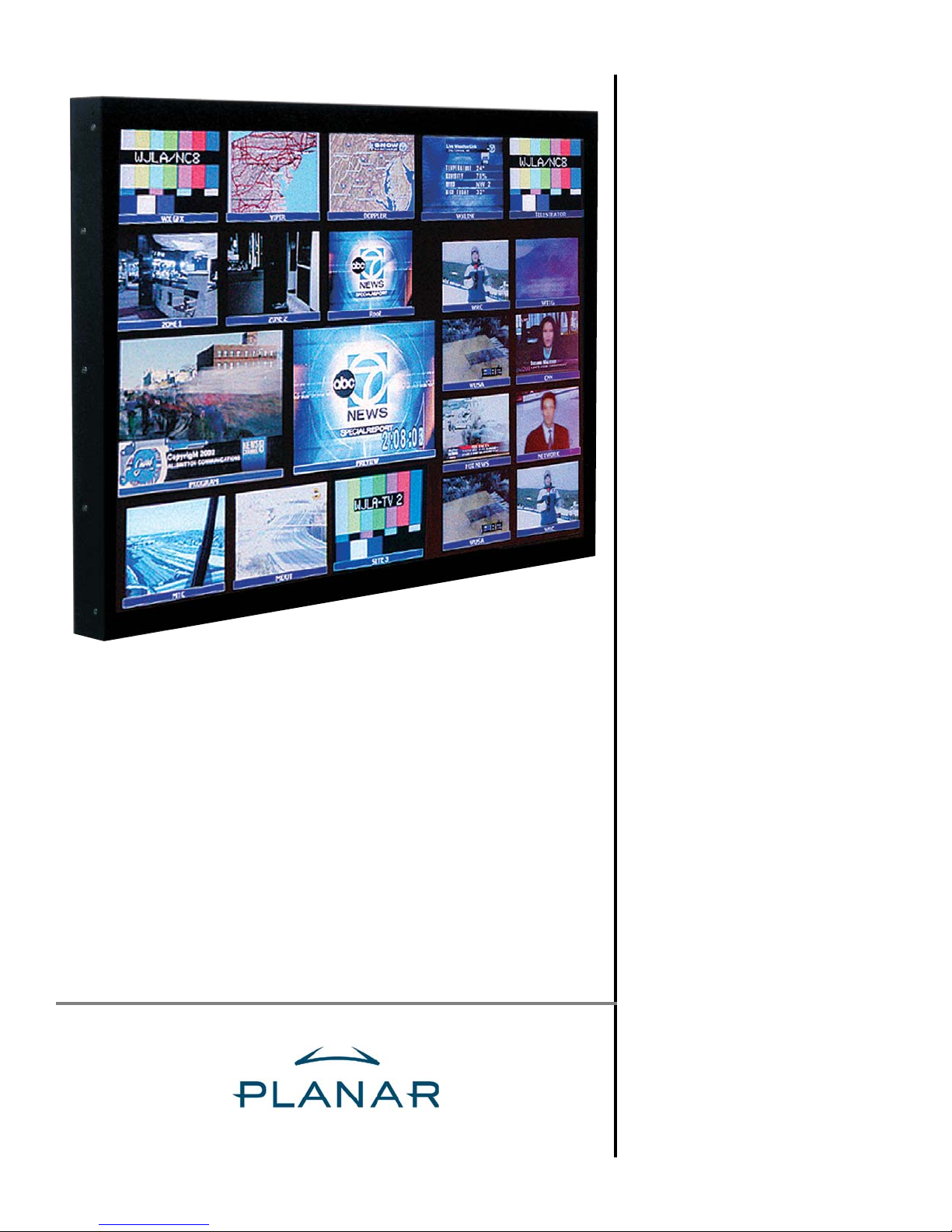
40" Direct-view LCD Panel
User Guide
020-0550-00B
Page 4

Copyright ©30 Jan 2007 by Planar Systems™, Inc. All Rights Reserved.
Contents of this publication may not be reproduced in any form without permission of Planar Systems, Inc.
Trademark Credits Windows™ is a trademark of Microsoft Corp.
APLCD® is a registered trademark Planar Systems, Inc.
All other names are trademarks or registered trademarks of their respective companies.
Disclaimer The information contained in this document is subject to change without notice. Planar Systems, Inc. Company
makes no warranty of any kind with regard to this material. While every precaution has been taken in the preparation of this
manual, Planar Systems shall not be liable for errors or omissions contained herein or for incidental or consequential damages
in connection with the furnishing, performance, or use of this material.
Limited Warranty Planar warrants to Buyer that the Bobcat X (hereinafter, the “Product”), if properly used and serviced,
will perform substantially in accordance with the product data sheet and users manual, and will be free from defects in material
and workmanship for one year following date of shipment. This warranty does not apply to air filters and other consumable
parts.
If any Product fails to conform to the written warranty, Planar's exclusive liability and Buyer's exclusive remedy will be, at
Planar's option, to repair, replace or credit Buyer's account with an amount equal to the price paid for any such defective Product returned by Buyer during the warranty period, provided that: (a) Buyer promptly notifies in writing that such Product failed
to conform, furnishes an explanation of any alleged deficiency and obtains from Planar a return authorization; and (b) Planar is
satisfied that claimed deficiencies actually exist and were not caused by accident, misuse, neglect, alteration, improper installation or repair, or improper testing. Planar will have a reasonable time to make repairs, to replace Products, or to credit
Buyer's account.
Limitations Any written warranty offered by Planar is in lieu of all other warranties, express or implied. Planar neither
assumes nor authorizes any other person to assume any other liabilities in connection with the sales or use of any product without limitation. Planar disclaims all other warranties, express or implied, including any warranty of merchantability or fitness
for a particular purpose. In no event will Planar be liable to buyer or any other party for procurement costs, loss of profits, loss
of use, or for any other incidental, consequential, indirect or special damages or for contribution or indemnity claims, however
caused. Planar's liability shall be limited to actual direct damages not in excess of the amounts paid to Planar by buyer for the
Product. These limitations will apply to all claims, including, without limitation, warranty, contract, indemnity, tort (including
negligence), strict liability or otherwise.
Quality Assurance Program To ensure long-term, top-quality performance of Planar’s direct-view LCD products, Planar
provides out-of-warranty coverage for image quality failures with a prorated replacement cost discount, as detailed below
For a period of three (3) years from the date of shipment, the Product is covered against temporary image retention (TIR)
and uneven display (UD), which is the formation of dark banding or streaking. If the Product exhibits TIR or UD that is visually objectionable in normal use during the original one (1) year warranty period, the Product shall be repaired or replaced
under Planar warranty policies and procedures. If the Product exhibits visually objectionable TIR or UD outside the warranty
period, Planar will discount the replacement or repair cost of the LCD panel on a monthly prorated basis up to a maximum of
three (3) years from the original shipment date. For example, if the Product fails in the 24th month from shipment, the customer will be charged 24/36 or 2/3 of the repair cost. Planar will absorb the remaining 1/3 of the cost of repair. The buyer is
responsible for shipping the Product back to Planar; Planar will cover the cost of shipping the repaired Product back to the
Buyer. Repair of the Product is the only warranty option. Planar will not refund the Buyer for the unused portion of the
expected product life. The replacement LCD is fully warranted for ninety days or the remainder of the original Product’s
expected life, whichever is shorter. The replacement LCD qualifies for the additional TIR warranty coverage for the remainder
of the original Product’s expected life. If TIR or UD symptoms can be rectified by turning off the Product or by displaying a
solid black image for two hours, and the Product shipped from Planar within the past three years, the LCD is not eligible for
replacement under the terms of the prorated replacement cost discount program
This prorated replacement cost discount program of LCD panel performance is exclusive of all other warranties written,
express, or implied. All other failure modes are excluded from this additional warranty coverage and strictly covered by the
original one (1) year limited warranty.
ii Bobcat X User Guide
Page 5

Table of Contents
1.1 What are the Main Features of Bobcat X? … 1
1.2 You Should Have These Accessories … 2
1.3 Safety for You and Bobcat X … 3
2.1 Installing the DVI Board … 7
2.2 Installing the Bobcat X Wall Bracket … 11
2.3 Hanging the Bobcat X on the Wall Bracket … 13
2.4 Connecting Power … 15
2.5 Connecting Picture Sources … 17
2.6 Connecting RS232 Communication … 19
3.1 Quick Start … 21
3.2 Setting Up a Bobcat X … 23
3.2.1 Selecting the Picture … 25
3.2.2 Adjusting Levels for Digital Sources … 29
3.2.3 Adjusting Levels for Analog Sources … 31
3.2.4 Adjusting Levels for Video Sources … 33
3.3 Aspect Ratio Settings … 35
3.3.1 Adjusting Sharpness … 41
3.3.2 Adjusting Position … 43
3.4 Tiling a Display … 45
3.5 Saving and Recalling Configurations … 47
3.5.1 Saving Configurations … 48
3.5.2 Recalling Stored Configurations … 51
3.5.3 Deleting a Configuration … 53
3.5.4 Memory: What Is Saved? And Where? … 54
3.5.5 Adjusting Color Balance … 57
3.5.6 Zoom and Position … 61
3.5.7 Viewport Adjustment … 63
3.6 Advanced Options … 65
3.6.1 Auto Setup Options … 66
3.6.2 Menu Options … 67
3.6.3 Miscellaneous Options … 68
3.6.4 Backlight Control … 69
3.7 Serial Port Settings … 71
3.8 Other Operations … 73
4.1 Cleaning the Screen … 75
5.1 Basic Bobcat X Troubleshooting Steps … 77
5.2 Reading the Status Menus … 81
iii
Page 6

5.3 Test Patterns … 83
6.4 Menu Structures … 85
6.5 Remote Control Buttons … 123
6.6 Drawings … 129
6.7 Connector Locations and Diagrams … 131
6.8 Optimizing Your Planar Display … 133
6.9 EDID: What It Is and How It Works … 135
Glossary of Terms … 137
Specifications for Bobcat X … 139
Regulatory Information … 141
Index … 143
iv
Page 7

v
Page 8

1.1 What are the Main Features of Bobcat X?
Flat screen, long backlight life (60,000 hours). Portrait or Landscape orientation
Bobcat X is a 40" LCD display that can be wall-mounted or
mounted on a stand. The display can be portrait or landscape.
Landscape
Bobcat X is only 3.96" deep. Its aspect ratio is 1.77
(16:9). Its native resolution is WXGA (1366 × 768). It
accepts a wide range of input pictures from VGA to UXGA
in either analog or digital (DVI).
For video it accepts NTSC, PAL, and SECAM as composite, component, or S-Video.
Most important, it is easy to set up and adjust.
What features were added to Bobcat X?
Bobcat X was developed from Bobcat II
(SN-4035-WX), and adds these features and enhancements.
Portrait
• Native WXGA resolution
• Increased contrast ratio of 1000:1
• Can be ordered in two different configurations: Base
Model and Video Model
• Automatic ambient light sensing and backlight adjustment
• 40 memory slots for easy configuration switching
• Improved video performance
• Improved component serviceability
• Optional tabletop feet
1
Page 9
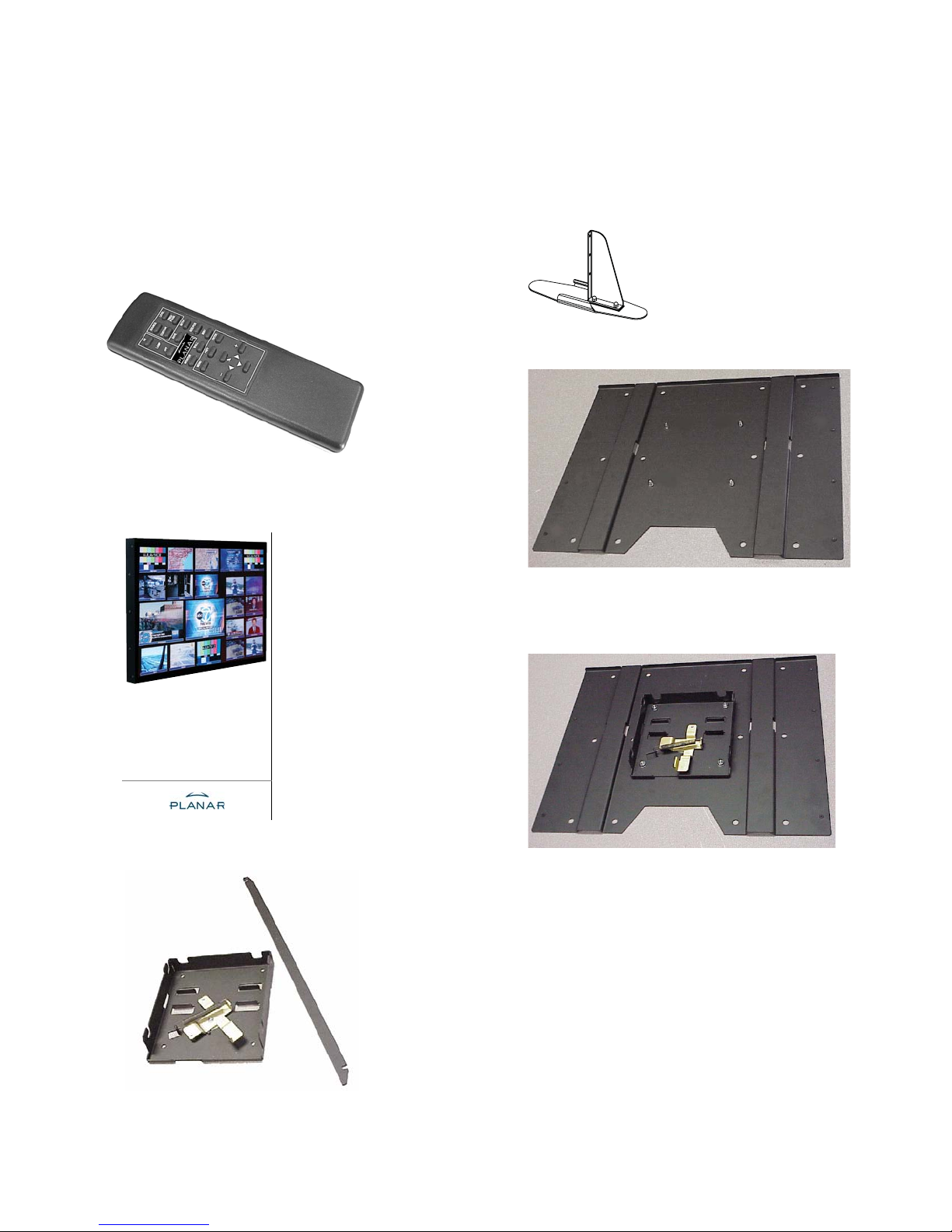
1.2 You Should Have These Accessories
Standard accessories
• 1 Power cord
• 1 VGA cable
•1 Remote control
• This User Guide
Optional accessories
• Free-standing feet
• Adapter Plate, WAL-4025-00, with hardware
Bobcat X
SN-4045-WX
The Adapter Plate comes with 4 nuts and 8 metric
screws. The 4 nuts hold the Wall Bracket to the Adapter
Plate.
User Guide
• Wall Bracket, with CATLOCK™ and locking tool
The Adapter Plate can be bolted to a wall. Or the
Adapter Plate can be screwed onto an NEC plasma monitor
display stand using the 8 metric screws.
2
Page 10
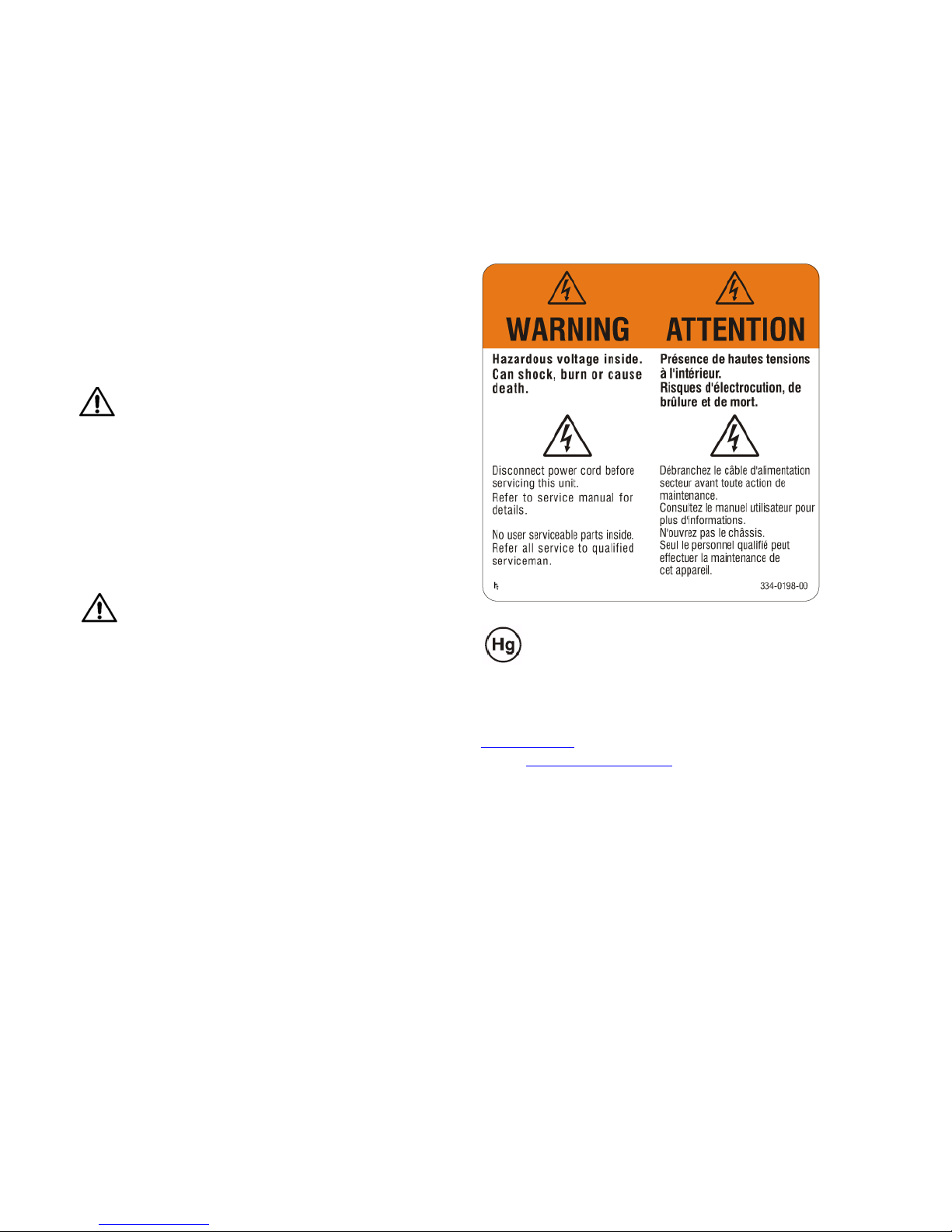
1.3 Safety for You and Bobcat X
This list of safety warning and caution notes isn’t very long. Reading it could save you from getting an electric
shock.
This display was designed with safety in mind. However, if you don’t heed the safety warning and cautions, you
could get hurt. The safety warning are on stickers in various
places in and on the display. They are reproduced on these
pages so you can see them all at once.
There are some other times you should know relating to
safety:
WARNING
Wall mounts must be secure.
If the displays are hung on a wall, the wall must be
strong enough to hold them. Each display unit weighs
about 55 lbs. (25 kg). Simply mounting it to wallboard or
wall paneling won’t be adequate or safe. The mounting
method must be capable of holding 5 times this weight, 275
lbs. (125 kg) for each display unit.
CAUTION
The screen could be damaged by heavy pressure.
Bobcat X screens are protected with a cover glass to
protect the LCD.
Some Bobcat Xs are shipped, at customer request, without this protective glass. In these, the LCD is not protected.
Slight pressure on the LCD will cause distortion of the
image. Heavier pressure will cause permanent damage.
Bobcat Xs of this type should be mounted where viewers
cannot touch the screen.
Lamp(s) inside this product contain mercury.
This product may contain other electronic
waste that can be hazardous if not disposed
of properly. Recycle or dispose in accordance with
local, state, or federal Laws. For more information,
contact the Electronic Industries Alliance at
www.eiae.org
check www.lamprecycle.org
. For lamp specific disposal information,
.
3
Page 11
(XURSHD
6LGHVHDGHVKDFHUVHGHHVWHSURGXFWRSyQJDVH
HQFRQWDFWRFRQODVDXWRULGDGHVORFDOHVRFRQVX
GLVWULEXLGRU\SLGDLQIRUPDFLyQVREUHHOPpWRGRGH
GLVSRVLFLyQDGHFXDGR
D\XGDDFRQVHUYDUORVUHFXUVRVQDWXUDOHV
(VWHVtPERORVRODPHQWHHVYiOLGRHQOD8QLyQ
PHGLRDPELHQWH\ODVDOXGKXPDQDFRQVHFXHQFLDVTXHSRGUtDQGDUVHVL
VHGHVKDFHGHOSURGXFWRGHIRUPDLQDGHFXDGD(OUHFLFODGRGHPDWHULDOHV
Ŷ 'HVKHFKRGHHTXLSRVHOpFWULFRV\HOHFWUyQLFRVDSOLFDEOHDOD8QLyQ(XUR
SHD\DRWURVSDtVHVHXURSHRVFRQSURJUDPDVGHUHFLFODMHLQGHSHQGLHQWHV
/DSUHVHQFLDGHHVWHVtPERORHQHOSURSLRSURGXFWRRHQVXPDWHULDOGH
HPEDODMHLQGLFDTXHQRVHGHEHWUDWDUFRPRUHVLGXRGRPpVWLFRFXDQGR
GHVHHGHVKDFHUVHGHpO(QVXOXJDUGHEHHQWUHJDUORHQHOSXQWROLPSLR
FRUUHVSRQGLHQWHGHUHFLFODMHGHHTXLSRVHOpFWULFRV\HOHFWUyQLFRV$VH
JXUiQGRVHGHTXHHVWHSURGXFWRVHGHVHFKDGHIRUPDFRUUHFWDD\XGDUi
DHYLWDUSRVLEOHVFRQVHFXHQFLDVQHJDWLYDVSDUDODFRQVHUYDFLyQGHO
7KLVV\PEROLVRQO\YDOLGLQWKH(XURSHDQ8QLRQ
,I\RXZLVKWRGLVFDUGWKLVSURGXFWSOHDVHFRQWDFW
\RXUORFDODXWKRULWLHVRUGHDOHUDQGDVNIRUWKHFRU
UHFWPHWKRGRIGLVSRVDO
(VSDxRO
QHJDWLYHFRQVHTXHQFHVWRWKHHQYLURQPHQWDQGKXPDQKHDOWKZKLFK
FRXOGRWKHUZLVHEHFDXVHGE\LQDSSURSULDWHGLVSRVDORIWKLVSURGXFW7KH
UHF\FOLQJRIPDWHULDOVZLOOKHOSWRFRQVHUYHQDWXUDOUHVRXUFHV
SRLQWIRUWKHUHF\FOLQJRIHOHFWULFDODQGHOHFWURQLFHTXLSPHQW%\HQVXULQJ
WKLVSURGXFWLVGLVSRVHGRIFRUUHFWO\\RXZLOOKHOSSUHYHQWSRWHQWLDO
7KLVV\PEROIRXQGRQ\RXUSURGXFWRURQLWVSDFNDJLQJLQGLFDWHVWKDW
WKLVSURGXFWVKRXOGQRWEHWUHDWHGDVKRXVHKROGZDVWHZKHQ\RXZLVKWR
GLVSRVHRILW,QVWHDGLWVKRXOGEHKDQGHGRYHUWRDQDSSOLFDEOHFROOHFWLRQ
Ŷ 'LVSRVDORIROG(OHFWULFDO(OHFWURQLF(TXLSPHQW$SSOLFDEOHWKURXJKRXW
WKH(XURSHDQ8QLRQDQGRWKHU(XURSHDQFRXQWULHVZLWKVHSDUDWHFROOHFWLRQ
SURJUDPV
(QJOLVK
VLFXUDQGRFKHLOFRUUHWWRVPDOWLPHQWRGLTXHVWRSURGRWWRVLDLXWHUjDSUHYH
QLUHSRWHQ]LDOLFRQVHJXHQ]HQHJDWLYHVXOO¶DPELHQWHHVXOODVDOXWHXPDQD
FKHSRVVRQRHVVHUHSURYRFDWHGDXQRVFRUUHWWRVPDOWLPHQWRGLTXHVWD
DWWUH]]DWXUD,PDWHULDOLULFLFODWLDLXWHUDQQRDFRQVHUYDUHOHULVRUVHQDWXUDOL
4XHVWRVLPERORqYDOLGRVRORQHOO¶8QLRQH(XURSHD
3HUVPDOWLUHTXHVWRSURGRWWRPHWWHUVLLQFRQWDWWRFRQ
OHDXWRULWjORFDOL±RFRQLOULYHQGLWRUH±HFKLHGHUH
LQIRUPD]LRQLVXOFRUUHWWRPHWRGRGLVPDOWLPHQWR
GHUHQGDWXGLWSURGXFWRSGHFRUUHFWHPDQLHUZHJZHUSWKHOSWXSRWHQWLsOH
QHJDWLHYHJHYROJHQYRRUKHWPLOLHXHQGHPHQVHOLMNHJH]RQGKHLGGLH
]RXGHQNXQQHQZRUGHQYHURRU]DDNWGRRUHHQRQUHFKWPDWLJZHJZHUSHQ
YDQKHWSURGXFWWHYRRUNRPHQ'HUHF\FODJHYDQPDWHULDOHQKHOSWKHW
EHKRXGYDQQDWXXUOLMNHEURQQHQ
'LWV\PERROLVDOOHHQJHOGLJLQGH(XURSHVH8QLH
$OVXGLWSURGXFWZHQVWZHJWHJRRLHQGLHQWXFRQWDFWRS
WHQHPHQPHWXZORNDOHLQVWDQWLHVYRRUGHWDLOVRYHUGH
JHSDVWHPHWKRGHYRRUDIYDOYHUZLMGHULQJ
GLVPDOWLUOR$OFRQWUDULRGHYHHVVHUHFRQVHJQDWRDGXQFHQWURGLUDFFROWD
VSHFLDOL]]DWRQHOULFLFODJJLRGLDWWUH]]DWXUHHOHWWULFKHHGHOHWWURQLFKH$V
ZLOWZHJZHUSHQ8PRHWKHWDIJHYHQELMHHQVSHFL¿HNYHU]DPHOSXQWYRRU
GHUHF\FODJHYDQHOHNWULVFKHHQHOHNWURQLVFKHDSSDUDWXXU'RRUWHJDUDQ
SURJUDPPLGLUDFFROWDGLIIHUHQ]LDWD
,OVLPERORWURYDWRVXOSURGRWWRRVXOODVXDFRQIH]LRQHLQGLFDFKHLO
SURGRWWRQRQSXzHVVHUHWUDWWDWRFRPHLGRPHVWLFLTXDQGRqLOPRPHQWR
DI]RQGHUOLMNHSURJUDPPD¶VYRRUDIYDOYHU]DPHOLQJ
'LWV\PERROGDWRSKHWSURGXFWRI]LMQYHUSDNNLQJLVDDQJHEUDFKWJHHIWDDQ
GDWGLWSURGXFWQLHWPDJZRUGHQEHKDQGHOGDOVKXLVKRXGHOLMNDIYDODOVXKHW
Ŷ 6PDOWLPHQWRGHOOHDWWUH]]DWXUHHOHWWULFKHHGHOHWWURQLFKHXVDWHDSSOLFDELOH
LQWXWWDOD&RPXQLWj(XURSHDHGDOWUL3DHVL(XURSHLFKHDSSOLFDQR
Ŷ 9HUZLMGHUHQYDQRXGHHOHNWULVFKHHQHOHNWURQLVFKHDSSDUDWXXUWRHSDV
VHOLMNLQGHYROOHGLJH(XURSHVH8QLHHQDQGHUH(XURSHVHODQGHQPHW
UHF\FODJHGHVPDWpULDX[FRQWULEXHUDpJDOHPHQWjpFRQRPLVHUOHVUHV
,WDOLDQR
SUHQGUHFRQWDFWDYHFOHVDXWRULWpVORFDOHVRXDYHFYRWUH
UHYHQGHXUHWUHQVHLJQH]YRXVVXUODPpWKRGHGHPLVH
DXUHEXWFRUUHFWH
1HGHUODQGV
:HQQ6LHGLHVHV3URGXNWHQWVRUJHQP|FKWHQZHQGHQ
6LHVLFKELWWHDQ,KUH|UWOLFKH%HK|UGHXQGIUDJHQ6LH
QDFKGHURUGQXQJVJHPlHQ(QWVRUJXQJVPHWKRGH
VRXUFHVQDWXUHOOHV
&HV\PEROHQ¶HVWYDODEOHTXHGDQVO¶8QLRQ(XURSpHQQH
6LYRXVVRXKDLWH]PHWWUHFHSURGXLWDXUHEXWYHXLOOH]
HLQ]XVSDUHQ
'LHVHV6\PEROLVWQXULQQHUKDOEGHUHXURSlLVFKHQ
*HPHLQVFKDIWJOWLJ
GHVHSURGXLUHHQFDVGHPLVHDXUHEXWLQDSSURSULpHGHFHSURGXLW/H
GLHVHV3URGXNWRUGQXQJVJHPl5HF\FOLQJKLOIWQDWUOLFKH5RKVWRIIH
DGpTXDWHYRXVFRQWULEXHUH]jSUpYHQLUOHVFRQVpTXHQFHVSRWHQWLHOOHPHQW
QpJDWLYHVVXUO¶HQYLURQQHPHQWHWVXUODVDQWpKXPDLQHTXLULVTXHUDLHQW
DXI8PZHOWXQG*HVXQGKHLWGLHGXUFKHLQHXQVDFKJHPlH(QWVRUJXQJ
GLHVHV3URGXNWHVHQWVWHKHQN|QQHQ]XYHUPHLGHQXQGHQWVRUJHQ6LH
YRXVYRXOH]OHPHWWUHDXUHEXW,OGRLWDXFRQWUDLUHrWUHUHPLVjXQVLWH
GHFROOHFWHDJUppSRXUOHUHF\FODJHGHVpTXLSHPHQWVpOHFWULTXHVHW
pOHFWURQLTXHV(QYHLOODQWjFHTXHFHSURGXLWVRLWPLVDXUHEXWGHIDoRQ
QLFKWDOV+DXVPOOEHKDQGHOWZHUGHQGDUI6WDWWGHVVHQVROOWHHVDQHLQH
6DPPHOVWHOOH]XP5HF\FOLQJYRQHOHNWULVFKHQXQGHOHNWURQLVFKHQ$OW
JHUlWHQJHJHEHQZHUGHQ+HOIHQ6LHPLWSRWHQ]LHOOVFKlGOLFKH(LQÀVVH
&HV\PEROHDSSOLTXpVXUYRWUHSURGXLWRXVXUVRQHPEDOODJHLQGLTXH
TXHFHSURGXLWQHGRLWSDVrWUHWUDLWpFRPPHXQGpFKHWPpQDJHUORUVTXH
'LHVHV6\PERO]X¿QGHQDXI,KUHP3URGXNWRGHUGHVVHQ9HUSDFNXQJ
PDFKW6LHGDUDXIDXIPHUNVDPGDVVGLHVHV3URGXNWEHLGHU(QWVRUJXQJ
Ŷ
0LVHDXUHEXWGHVpTXLSHPHQWVpOHFWULTXHVHWpOHFWURQLTXHVXVDJpV
9DODEOHGDQVO¶HQVHPEOHGHO¶8QLRQ(XURSpHQQHDLQVLTXHGDQVOHVSD\V
HXURSpHQVGLVSRVDQWGHSURJUDPPHVGLVWLQFWVGHFROOHFWHGHVGpFKHWV
)UDQoDLV
Ŷ (QWVRUJXQJYRQHOHNWULVFKHQHOHNWURQLVFKHQ$OWJHUlWHQJHOWHQGIUGLH
HXURSlLVFKH*HPHLQVFKDIWXQGDQGHUHHXURSlLVFKH/lQGHUPLWVHSDUDWHQ
6DPPHOSURJUDPPHQ
'HXWVFK
4
Page 12

QDWXUWLOOJnQJDU
KlOVD'HWNDQDQQDUVRUVDNDVSnJUXQGDYROlPSOLJVRSKDQWHULQJDYGHQ
KlUSURGXNWHQcWHUYLQQLQJDYPDWHULDONRPPHUDWWKMlOSDWLOODWWEHYDUD
WLOOI|UVlNUDDWWGHQKlUSURGXNWHQnWHUYLQQVSnHWWULNWLJWVlWWKMlOSHUGXWLOO
PHGDWWI|UKLQGUDP|MOLJDQHJDWLYHNRQVHNYHQVHUI|UPLOM|QRFKPlQVNOLJ
SnYLVDUDWWSURGXNWHQLQWHVNDEHKDQGODVVRPKXVKnOOVDYIDOOQlUGXYLOO
VOlQJDERUWGHQ,VWlOOHWVNDGHQOlPQDV|YHUWLOOHQOlPSOLJXSSVDPOLQJV
SXQNWI|UnWHUYLQQLQJDYHOHNWULVNDRFKHOHNWURQLVNDXWUXVWQLQJDU*HQRPDWW
VDPOLQJVSURJUDP
'HQKlUV\PEROHQVRP¿QQVSnGLQSURGXFWHOOHUSnGHVVI|USDFNQLQJ
Ŷ$YIDOODYI|UEUXNDGHOHNWULVNRFKHOHNWURQLVNXWUXVWQLQJ7LOOlPSEDUWL
KHOD(XURSHLVNDXQLRQHQRFKDQGUDHXURSHLVNDOlQGHUPHGVHSDUDWD
FLDOPHQWHQHJDWLYDVWDQWRSDUDRDPELHQWHFRPRSDUDDVD~GHKXPDQD$
UHFLFODJHPGHPDWHULDLVDMXGDDSUHVHUYDURVUHFXUVRVQDWXUDLV
XLSDPHQWRVHOpFWULFRVHHOHFWUyQLFRVSDUDSRVWHULRUUHFLFODJHP$RJDUDQWLU
DFRUUHFWDHOLPLQDomRGHVWHSURGXWRHVWDUiDHYLWDUFRQVHTXrQFLDVSRWHQ
HOLPLQDomR(PYH]GLVVRGHYHVHUHQWUHJXHQXPSRQWRGHUHFROKDGHHT
(VWHVtPERORFRORFDGRQRSURGXWRRXQDUHVSHFWLYDHPEDODJHPLQGLFD
TXHRSURGXWRQmRGHYHVHUWUDWDGRFRPROL[RGRPpVWLFRDTXDQGRGDVXD
3RUWXJXrV
Ŷ (OLPLQDomRGHHTXLSDPHQWRVHOpFWULFRVHHOHFWUyQLFRVXVDGRVDSOLFiYHO
QD8QLmR(XURSHLDHQRXWURVSDtVHVHXURSHXVFRPSURJUDPDVSUySULRVGH
UHFROKDGHVWHVHTXLSDPHQWRV
IUnJDHIWHUOlPSOLJDYIDOOVPHWRG
'HQKlUV\PEROHQlUHQGDVWJLOWLJLQRPGHQ
(XURSHLVNDXQLRQHQ
2PGXYLOOVOlQJDERUWGHQKlUSURGXNWHQVNDGX
NRQWDNWDORNDODP\QGLJKHWHUHOOHUnWHUI|UVlOMDURFK
KlYLWHWWlHVVlNlVLWHOOlWDYDOOLVHQDNRWLWDORXVMlWWHHQlYDDQVHNXXOXXWRLPLW
WDDVlKN|MDHOHNWURQLLNNDODLWWHLGHQNLHUUlW\VSLVWHHVHHQ9DUPLVWDPDOOD
HWWlWlPlWXRWHKlYLWHWllQDVLDDQNXXOXYDOODWDYDOODDXWDWHVWlPllQPDK
GROOLVLD\PSlULVW|OOHMDLKPLVLOOHNRLWXYLDQHJDWLLYLVLDVHXUDDPXNVLDMRLWD
VHQYllUlQODLQHQKlYLWWlPLQHQYRLDLKHXWWDD0DWHULDDOLHQNLHUUlWWlPLQHQ
DXWWDDVlLO\WWlPllQOXRQQRQYDURMD
7lPlV\PEROLRQYRLPDVVDDLQRDVWDDQ(XURRSDQ
XQLRQLQDOXHHOOD
-RVKDOXDWKlYLWWllWlPlQWXRWWHHQRWD\KWH\WWl
SDLNDOOLVLLQYLUDQRPDLVLLQWDLMlOOHHQP\\MllQMDWLHGXVWHOH
DVLDDQNXXOXYLDKlYLWWlPLVWRLPHQSLWHLWl
Ŷ9DQKRMHQVlKN|MDHOHNWURQLLNNDODLWWHLGHQKlYLWWlPLQHQ6RYHOWXYDNDLN
NLDOOD(XURRSDQXQLRQLQDOXHHOODVHNlPXLVVD(XURRSDQPDLVVDMRLOODRQ
HULOOLVHWNHUl\VRKMHOPDW
-RVWXRWWHHVVDWDLVHQSDNNDXNVHVVDRQWlPlV\PEROLVLWlHLSLGl
(VWHVtPERORDSHQDVpYiOLGRQD8QLmR(XURSHLD
6HTXLVHUHOLPLQDUHVWHSURGXWRFRQWDFWHDVHQWL
GDGHVORFDLVRXRVHXIRUQHFHGRUSDUD¿FDUDVDEHU
TXDORPpWRGRGHHOLPLQDomRFRUUHFWR
6YHQVND
6XRPL
7HQV\PERORERZLą]XMHZ\áąF]QLHZNUDMDFK8QLL
(XURSHMVNLHM
,QIRUPDFMHGRW\F]ąFHSUDZLGáRZHMPHWRG\XVXQLĊFLD
WHJRSURGXNWXPRĪQDX]\VNDüXZáDG]ORNDOQ\FKOXE
XGRVWDZF\
NUDMyZ8QLL(XURSHMVNLHMLLQQ\FKNUDMyZHXURSHMVNLFK]RGG]LHOQ\PL
SURJUDPDPL]ELyUNLRGSDGyZ
2EHFQRĞüWHJRV\PEROXQDSURGXNFLHOXEQDRSDNRZDQLX]SURGXNWHP
R]QDF]DĪHWHJRSURGXNWXQLHPRĪQDZ\U]XFDüUD]HP]RGSDGNDPL
GRPRZ\PL1DOHĪ\JRSU]HND]DüGRSXQNWX]ELyUNLZFHOXSRGGDQLD
UHF\NOLQJRZLSRG]HVSRáyZHOHNWU\F]Q\FKLHOHNWURQLF]Q\FK8VXQLĊFLHWHJR
SURGXNWXZSUDZLGáRZ\VSRVyESRPRĪHZ]DEH]SLHF]HQLXSU]HGQHJDW\
ZQ\PZSá\ZHPRGSDGyZQDĞURGRZLVNRL]GURZLHOXG]LSRZRGRZDQ\P
SU]H]QLHZáDĞFLZHXVXZDQLHSURGXNWX3U]HWZDU]DQLHPDWHULDáyZSRPDJD
Z]DFKRZDQLX]DVREyZQDWXUDOQ\FK
Ŷ 8VXZDQLH]XĪ\WHJRVSU]ĊWXHOHNWU\F]QHJRLHOHNWURQLF]QHJR'RW\F]\
3ROVNL
5
Page 13

6
Page 14
2.1 Installing the DVI Board
Planar Systems ships the DVI board separately from the Bobcat X to some customers and for field upgrades.
✎
The DVI Board is the field-installed video board for
the Video Model of Bobcat X.
1. If you powered up the unit to confirm proper working
order upon receipt, turn off AC power to the Bobcat X
and remove the power cord.
2. Place the unit face down on a flat surface on something
soft and non-scratching. If your unit does not have a
protective face glass panel, be EXTREMELY careful as
the LCD material can be scratched.
3. Confirm that your DVI Board package contains four (4)
mounting screws, a replacement DVI cover panel, and a
disposable grounding wrist strap.
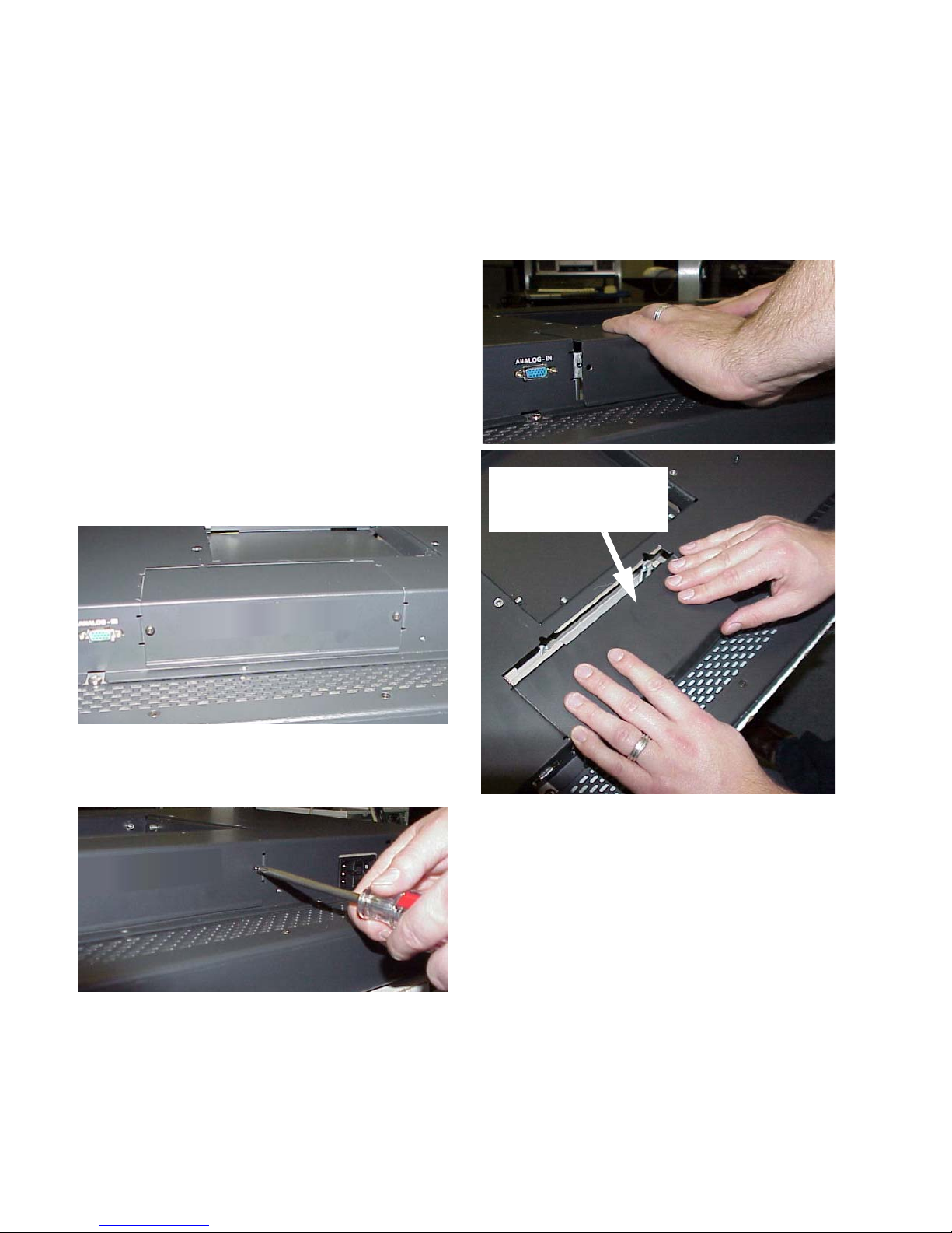
4. On the back of the Bobcat X, remove the blank cover
panel.
b) Remove the blank panel by pushing down slightly
on the inserted end of the panel as you pull it out.
As you remove the panel,
push down slightly on this
end of the panel as you pull
it towards you
a) Unscrew the two screws holding the blank panel in
place. Save the screws for the replacement panel you
will install later.
7
c) Recycle the blank panel with other aluminum scrap
metal.
5. Attach the grounding wrist strap to bare metal on the
chassis. Using standard ESD procedures, remove the
Page 15
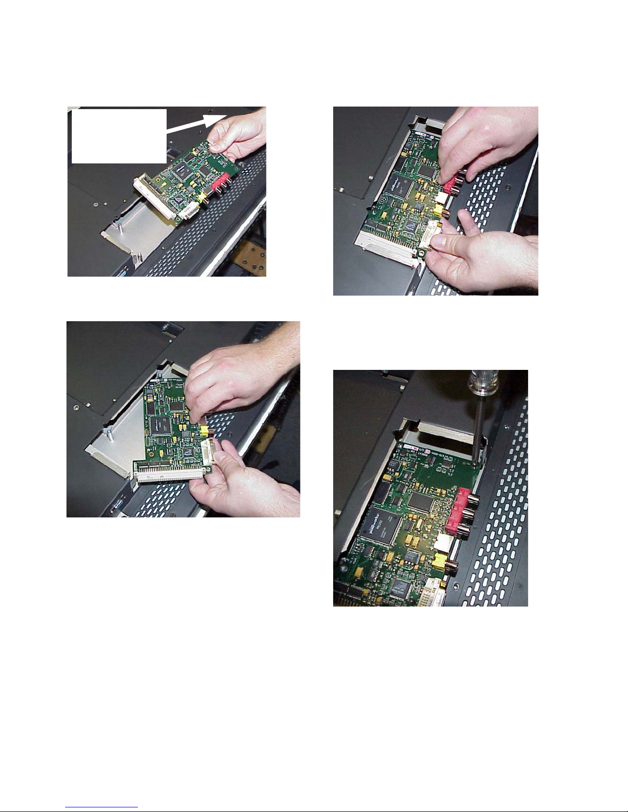
DVI board from the anti-static bag. (The DVI board is
shown in the pictures below.)
Use a grounding wrist
strap (not shown) or
other personal ESD
devices to prevent
damage to the board
6. Carefully slide the right side of the board into the slot
on the right side of the opening.
7. Align the connector on the board with the connector in
the opening.
Gently push the board into the connector. The board is
fully seated when the four screw holes are aligned.
8. Screw down the four corners of the DVI board with the
supplied mounting screws.
8
Page 16
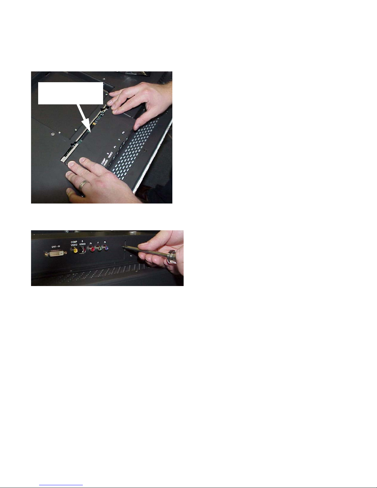
9. Slide the DVI replacement cover panel into place. Press
down gently on the insertion end of the panel to help
the tabs insert in the slots.
As you insert the panel,
push down slightly on this
end of the panel
10. Secure the DVI replacement cover panel using the
screws you removed earlier.
9
Page 17

10
Page 18
2.2 Installing the Bobcat X Wall Bracket
The Bobcat X hangs on its wall bracket in either landscape or portrait orientation.
Installing the wall bracket
The wall bracket comes with each Bobcat X. See picture
in “You Should Have These Accessories” on page 2.
Using hardware you supply, bolt or screw the wall
bracket to a wall. Be sure to bolt or screw to structural elements of the wall, not just the wall board or drywall. The
Bobcat X weighs 55 lbs. (25 kg). The mounting method
you use must be capable of holding five times this weight
(265 lbs., 120 kg). The mounting holes are on 6.26" centers. When installed, the wall bracket protrudes 0.375" from
the back panel of the Bobcat X.
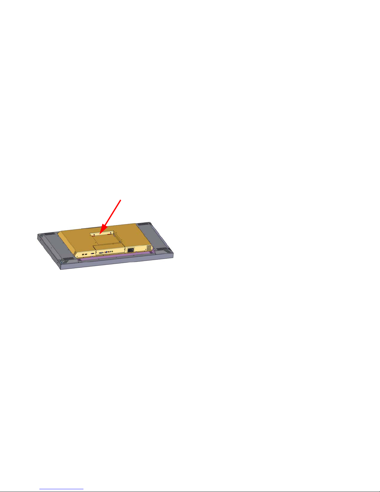
✎ This space at the rear of the Bobcat X will
be occupied by the wall bracket when the
display is hanging on a wall.
Ventilation
The Bobcat X needs no space to the rear for ventilation.
However, like all electronic devices, it does produce some
heat. The space above the display should provide enough
space so that heated air can get away. This means you
should not mount it into a sealed space with nowhere for
the heated air to escape.
Portrait or Landscape
The wall bracket always mounts the same way, whether
the displays will be hung as portrait or landscape. The
hooks on the wall bracket should always have the open part
facing upward.
✎ The Locking Wall Bracket does not have the
large back plate. It consists of the square, open
box with the locking mechanism. This Locking
Wall Bracket with CATLOCK™ is a standard
accessory.
For array mounting guidelines, contact Planar Systems.
11
Page 19

12
Page 20
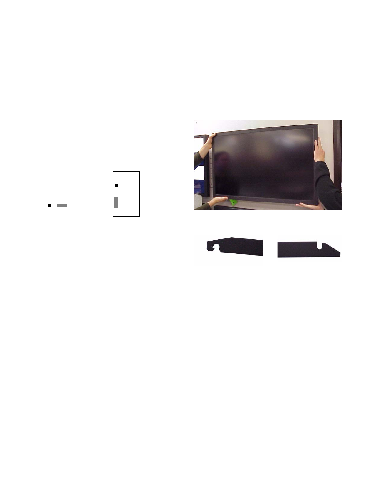
2.3 Hanging the Bobcat X on the Wall Bracket
The locking system for the Bobcat X wall bracket prevents the display from jumping off the bracket during earth
tremors, and it helps deter theft.
Two-person job
The Bobcat X weighs just over 55 lbs. (25 kg). Always
have two persons hang the display on the wall bracket.
Two orientations
The Bobcat X hangs in either landscape or portrait orientation. The small black square shows the position of the
AC power receptacle. The gray rectangle shows the position of the picture connectors, when viewed from the front.
Landscape
Portrait
✎ The Bobcat X will not rotate the picture. The
source (computer or video source) must rotate the
picture. The Bobcat X can rotate the menus, so
the internal menus will be upright with either
orientation.
Hanging the display
Before you hang the first display, practice using the lock
lever to open and close the locking mechanism.
4. Use the locking tool to lock the display onto the wall
bracket. To see if it is locked in place, try to lift the display. If it won’t lift, its locked.
Locking and unlocking
This end of the locking tool
works from below the wall
bracket.
This end of the locking tool
works from the sides of the
wall bracket.
✎ After the display is hung, the connectors for video
and power are a little difficult to see. Some
installers connect power and video cables just
before hanging the display.
1. Be sure the locking lever is in the open position. The
tab on the lever should not protrude below the bottom
of the box.
2. Using two persons, lift the display so the power receptacle is at the bottom for landscape hanging.
✎ For portrait orientation, the power receptacle will
be on the left, looking from the front.
3. Hang the display in the hooks. Pull forward on the display to see that it is properly in the hooks.
13
Page 21
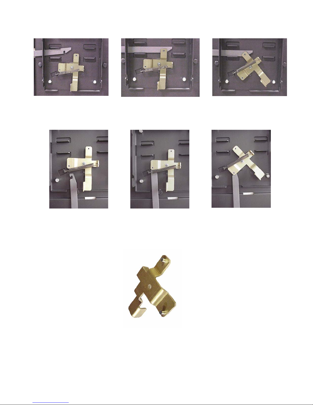
Unlocking from the side: Slide the tool in from the side. It will ride up
over the lock and catch it. Pull the lock back to unlock.
Unlocking from the bottom: Slide the tool in from the bottom, keeping the open side of the hook to the left, as shown. Catch the lock and
pull down.
Back side of the locking lever, showing the
two pins that the tool hooks onto.
14
Page 22
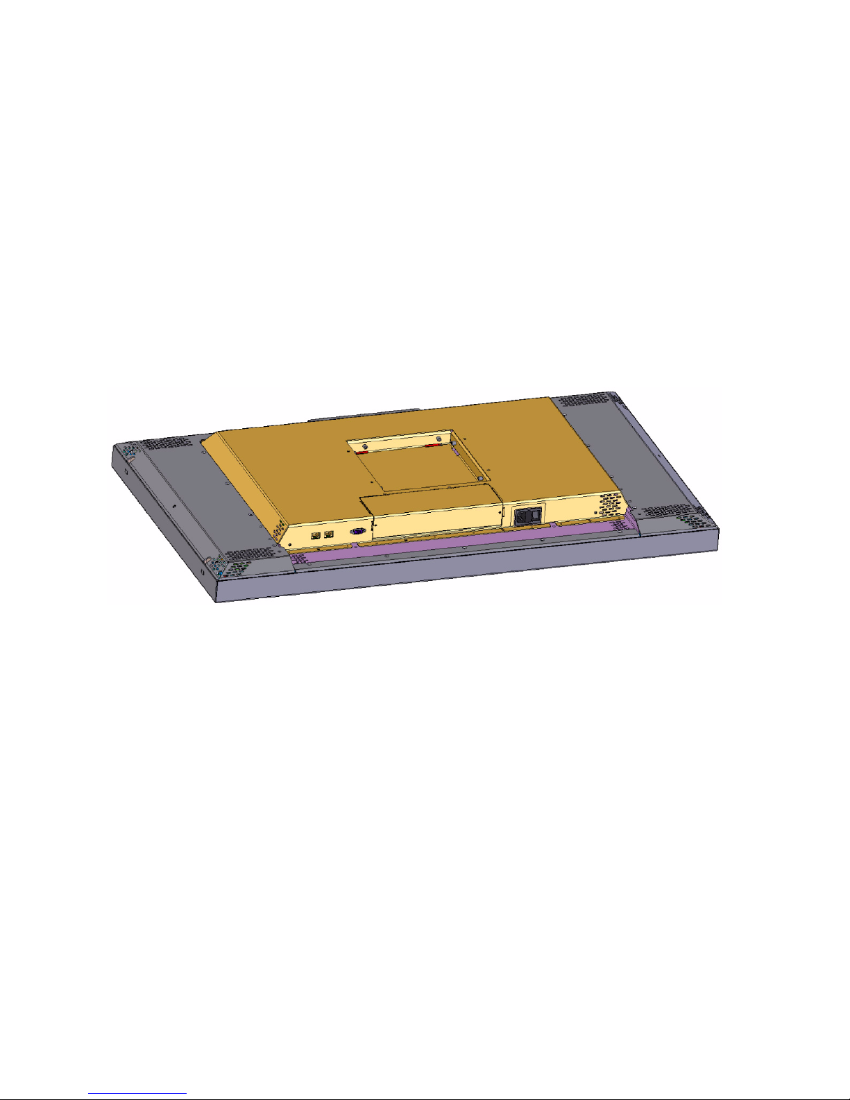
2.4 Connecting Power
Bobcat X accepts 110-120 VAC and 200-240 VAC with no manual switching. It is the responsibility of the
installer to provide the power supply cord certified for use in the destination country.
Plug the power cord into the receptacle on the rear of the
Bobcat X. Plug the other end into a good source of AC
power.
When ready, turn on the power switch.
Normal operation
It is normal to leave the power connected and the power
switch on all the time and turn the backlight on and off as
desired.
For power receptacle dimensions, see see “Connector
Locations and Diagrams” on page 131.
Power receptacle and power switch location
15
Page 23

16
Page 24

2.5 Connecting Picture Sources
The Bobcat X accepts inputs from many different sources, depending on configuration
Which Configuration Do You Have?
The Bobcat X can be ordered in one of two configura-
tion: Base Model or Video Model.
Base Model Inputs
The base model has on analog computer video input port
and two RS232 ports (input and output). You may connect
standard sources ranging from VGA to UXGA and 480i,
480p, 720p, or 1080i to the analog video input port.
Video Model Inputs
The Video Model has a total of five different inputs. Of
these five different video inputs, four are the same for both
models: Analog, Composite, S-Video, and Component
(YPbPr).
The fifth connector on the Video Model is a DVI input
port that accepts all video and graphics signal inputs up to
165MHz pixel clock.
Computer sources
Connect analog computer sources to the analog connector or on Video Models, connect digital computer sources
to the DVI connector.
Most DVD players have red, green, and blue RCA con-
nectors for component video output.
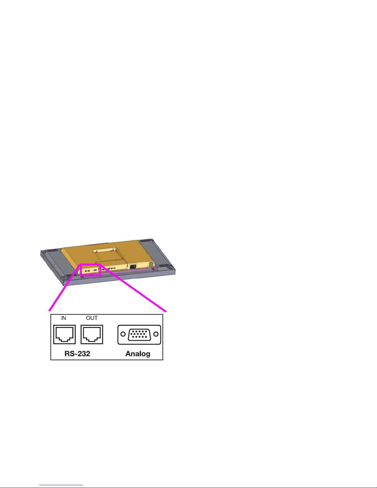
Connectors and Locations
The locations of the connectors are show in the illustra-
tion on 7.
✎ For exact locations and dimensions of connectors,
see “Connector Locations and Diagrams” on
page 131.
Since computer sources are RGB, you must set the Colorspace to RGB in the Picture menu.
Video Sources
Connect composite video sources to the yellow RCA
connector, S-Video sources to the S-Video connector, and
component video sources to the red, green, and blue RCA
connectors.
Component and S-Video connectors accept NTSC and
PAL video sources. The composite connector also accepts
SECAM video sources.
✎ For some customers and field upgrades, video
boards are shipped separately and must be
installed prior to use. For more information, see
“Installing the DVI Board” on page 7.
YPbPr sources
Component video sources, such as those provided by
some DVD players, should be connected to the component
connectors. These connectors accept 480i and 576i signals
(480p and HD signals are not accepted).
17
Page 25
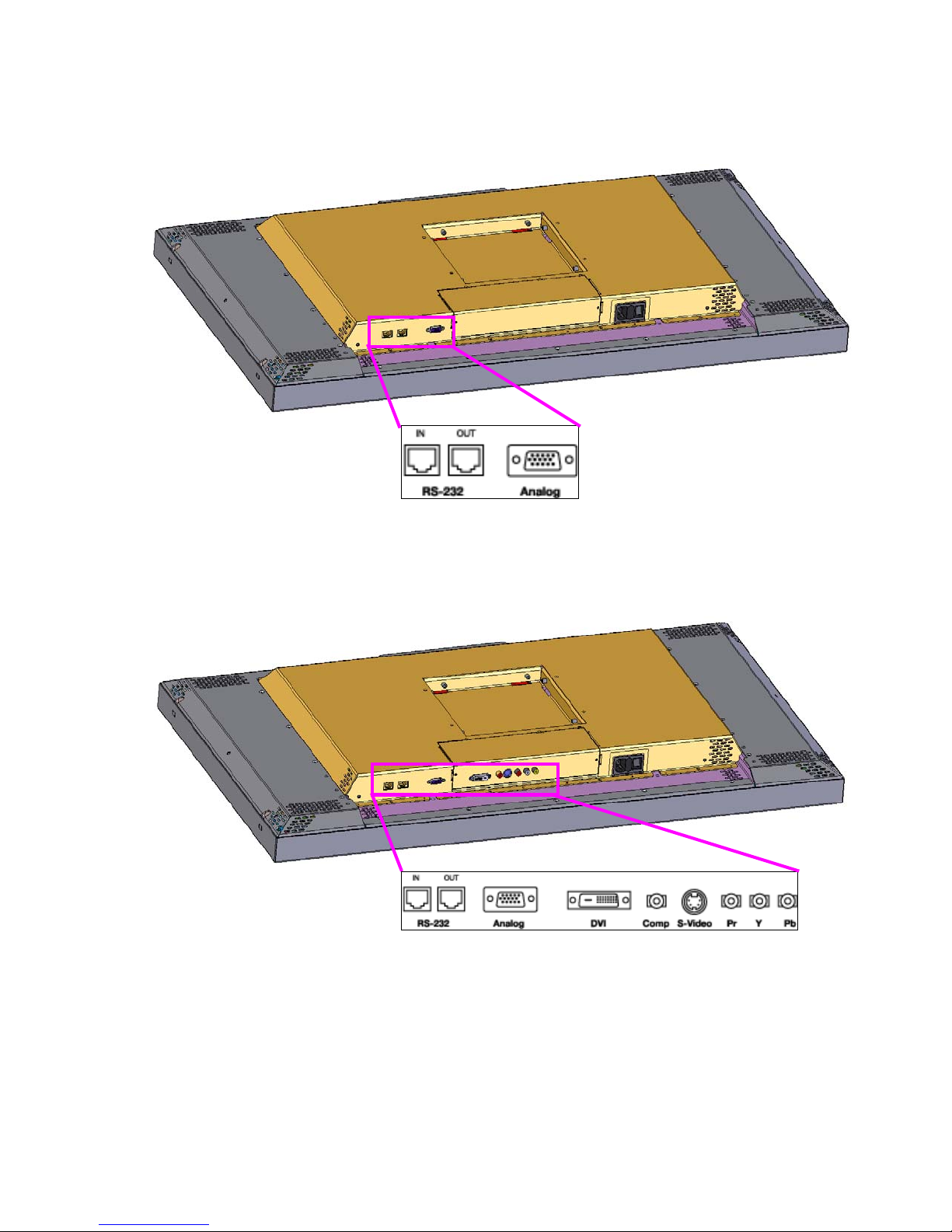
The Video Model
The Base Model (shown above) has
only and Analog VGA connector.
18
Page 26
2.6 Connecting RS232 Communication
5 4 3 2 1
6789
RS232 control is not necessary for operation, but it is a convenient way to control Bobcat Xs from a distance. If
your installation will not use RS232 control, skip this section.
RS232 control has one big advantage: you can control all
the units from a computer at a considerable distance from
the wall. You can control:
• units one at a time;
• several video walls separately;
• all the units in all the walls at the same time.
Almost everything you can do with the remote, you can
do with RS232 commands. Plus, you can send inquiries to
the units and find out the current settings and values.
RS232 connections are made with cables like those used
for computer networks. These cables have eight (8) conductors and have RJ-45 connectors on each end.
✎ It is important that the cable has “straight through”
connections. To know if your cable is correct, hold
the two connectors side by side with the ends
pointing in the same direction. Look at the side of
the connectors that do not have the locking tab. If
the colors of the wires inside the connector are the
same left to right for both connectors, this is the
correct cable. If the colors are mirror reflections of
each other, it is the wrong type.
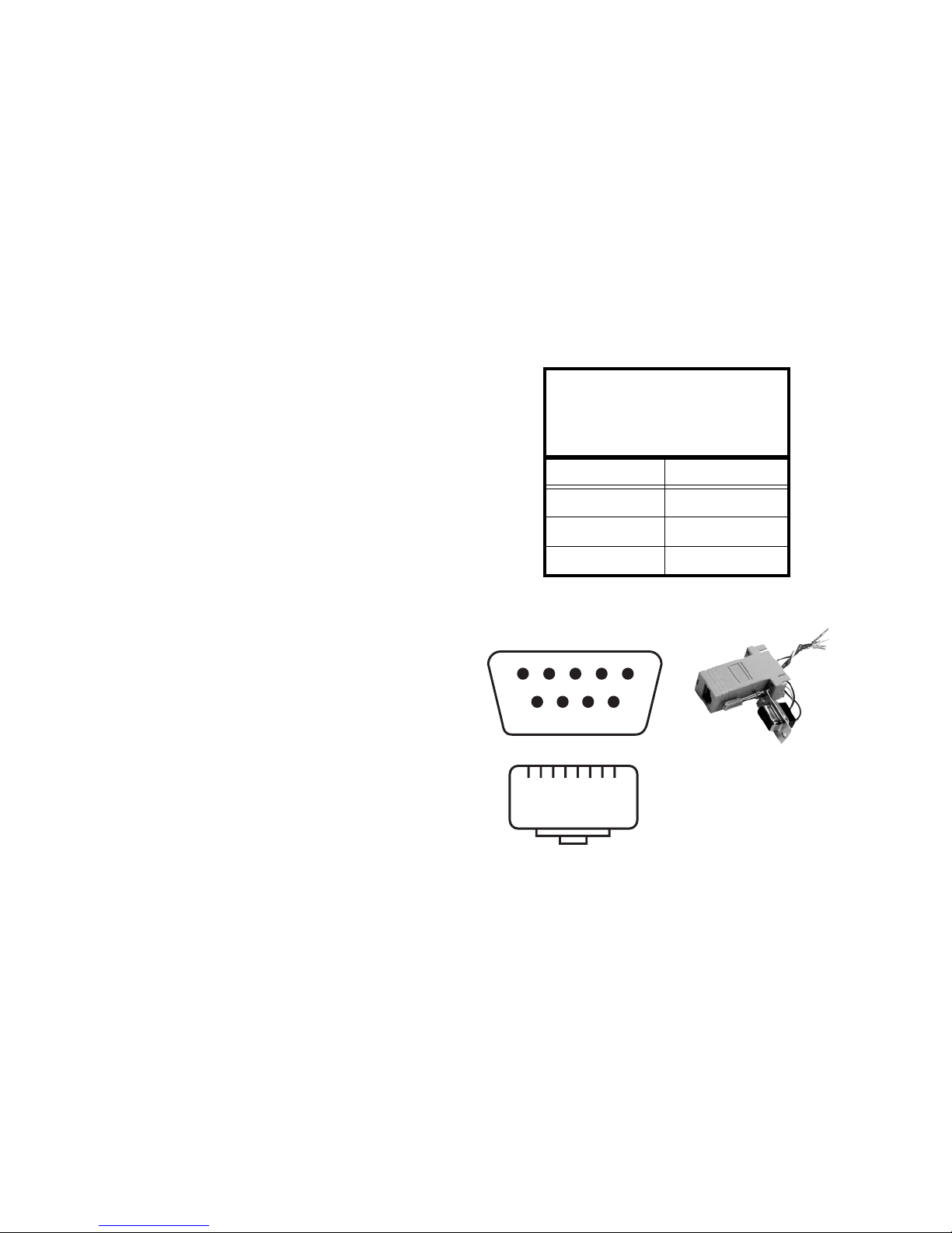
Wiring the adapter
To go from 9-pin D-sub serial connector on the back of the
computer to an RJ45 connector, use a standard
RJ45-to-9-pin adapter. Wire it internally as shown. The
wiring shown for this adapter is correct for straight-
through cables. Straight-through cables are wired 1-to-1,
2-to-2, etc.
Yellow wire pin 3
Black wire pin 2
Green wire pin 5
RJ45 9-pin
63
55
32
You need an adapter to go from the computer’s 9-pin serial
output connector to an RJ-45 connector. Adapters of this
type are readily available at computer and electronic supply
stores. You will only need one adapter; all the rest of the
connections will be RJ-45 to RJ-45.
The adapter is not pre-wired. You will make three connections inside the adapter, as described below.
1
RJ45 looking into the socket
Connecting RS232 cables
1. Connect the adapter to the serial output connector of
the controlling computer. (This computer does not have
to be the same one as the computer used as a picture
source.) The serial output is sometimes called the
Comm Port, and sometimes there are two.
8
✎ If the serial output is a 25-pin connector, use a 25-
to-9-pin adapter, then the 9-pin to RJ-45 adapter.
19
Page 27
2. Connect a cable from the RJ-45 adapter to the nearest
unit’s RS232 In connector.
3. Connect this first unit’s RS232 Out connector to the
next unit’s RS232 In connector.
4. Continue in this way until all units are connected.
✎ The order in which you connect the units is not
important. You can connect them in any order that
is convenient and keeps the cable lengths to a
minimum.
From the first unit, connect RS232 Out to the next unit’s
RS232 In. Continue in this way until all units are in the
loop. The order of units in the loop does not matter because
each unit in the array must have a unique address.
✎ The loop-through limit is approximately 30 units in
typical situations. However, if the units are spaced
far apart or the total length of the loop-through is
very long, this limit may be reduced. You may
need multiple RS232 sources.
For information about configuring RS232 communications, see “Serial Port Settings” on page 71.
RS232 Connector Location
For exact locations and dimensions of connectors, see
“Connector Locations and Diagrams” on page 131.
20
Page 28

3.1 Quick Start
After you select the picture source, most of the rest of setup is automatic, although you can override the automatic
settings and adjust anything manually.
Selecting the source means choosing the connector where
the picture is coming in. You’ll chose from the following
connectors, depending on the model:
Base Video
Analog Analog
DVI
Composite
S-Video
Component (YPbPr)
Quick start
Connect power and turn on the power switch, which should
light. The backlight will come on automatically. If the
power was already on, and the backlight is off, press the
remote
ON button.
1. Aim the remote control at the lower right corner (in
landscape mode; in portrait mode, it is in the lower left
corner of the Bobcat X) and press
SOURCE on the
remote.
ON
LAMP
OFF
SOURCE
CURTAIN
SAVE
LEVEL
FREQ/
PHASE
SETUP
2. Press
MENU. The Main Menu displays on the screen
Main Menu
Picture
Size & Position
Aspect Ratio & Wall
Memory
Diagnostics
Advanced Options
Program Information
3. Select Picture with the up-down arrow keys on the
remote and press
Picture
Source Analog 2
Colorspace RGB
Sync Type Separate H&V
Vertical Frequency (frame locked) 60Hz
Horizontal Frequency 1080 kHz
Pixel Frequency 1280MHz
Horizontal Resolution 1280
Vertical Resolution 768
Frequency
Phase
ENTER. This opens the Picture menu.
1232
100.0
The Bobcat X looks at each of the connectors and stops
on the first one that is receiving a valid picture.
If this is successful (it may take 10 seconds) stop here.
If you have several sources connected, press
again to go to the next one with a picture.
If you get no picture or have other trouble, read the rest
of these steps.
✎ If you use a video source (such as from a
progressive DVD player) on the Analog or Digital
inputs, manually change the Colorspace to YPbPr.
Otherwise the colors will be wrong.
21
Sharpness Sharpest
Input Levels
SOURCE
Page 29
✎ TIP: The FREQ/PHASE button opens the Picture
Landscape
Portrait
IR Receiver
and Power LED
menu directly.
• The IR receiver for the remote is a small hole in the
lower left corner of the display. Be sure the remote is
aimed toward it. (In Portrait orientation the IR receiver
is in the lower left corner.
About the remote
The remote control operates with IR (infra-red) signals
going to the IR receiver. The receiver is in the lower right
corner (in landscape mode; in portrait mode, it is in the
lower left corner) of the screen bezel behind a small hole.
4. Select Source and press E
NTER. This opens the
Source menu (the menu shown below is from the
Video Model; the Base Model have different options):
Analog
Digital
Component (YPbPr)
S-Video
Composite
5. With the UP or DOWN arrow keys, select the input
connector you want:
All Models Analog, usually computer sources,
VGA through UXGA
Video Model Digital (DVI connector)
Component
Composite Video
S-Video
(Later, to prevent accidental adjustment of the display,
disable the remote control function using an RS232 command.)
A quick reference for all the remote buttons is found in
“Remote Control Buttons” on page 123.
If the remote doesn’t work
• The batteries in the remote are dead or installed wrong.
• The remote was not aimed at the screen.
• Something is blocking the IR receiver in the Bobcat X.
• IR remote action was disabled by an RS232 command.
✎ The remote control has a large spread of its IR
radiation. It is difficult from a distance to control
only one Bobcat X in an array. Step closer.
6. Press
ENTER. The Bobcat X will immediately display
the picture. Within a second or two the Bobcat X will
analyze the picture and adjust to it.
If you see no picture …
• Check the source by connecting it to another type of
display. If the source is a laptop, maybe it has timed out
and the screen is blank. Did you enable the VGA output
on the rear of the laptop?
• Check the power switch near the AC power cord. It
should be lit.
22
Page 30

3.2 Setting Up a Bobcat X
The source picture—from computer, video, DVD—is not always perfect in its size or resolution; it does not always
conform exactly to a standard. Bobcat X can compensate for this.
You’ll find it easier to configure your Bobcat Xs when you
perform the steps in the following order:
• Select the Source (Picture)
• Adjust the Input Levels
• Select the Scale Mode
• Adjust the Sharpness
• Check the Image Position
Then if you are using multiple units, whether in a ban-
ner, tower, or wall, perform the remaining steps:
• Set up Tiling for the image on multiple units
• Adjust Scaling and Cropping
• Color Balance the units
Computer sources vary quite a bit from computer to computer. They even vary between video outputs on the same
video card. Video sources vary more.
To make the Bobcat X respond correctly to these non-
standard sources we adjust Input Levels.
How does Input Level relate to Color Balance?
To make all the displays show the same color and brightness across the whole array, you need to adjust input levels
and do color balancing.
The Input Level adjustment process asks you to provide
a picture from the computer that is black, then one that is
pure white. With these, you can quickly and automatically
make the display “learn” what this computer means by
black and white.
The result? Good pictures, using all the dynamic range
of color coming from the computer.
✎ For Input Levels, if you must use black and white
coming from the computer you will use for the
program. Don’t make this adjustment with your
work laptop and then switch to another computer
for the display’s program of pictures.
What does Color Balance do?
Color balancing adjusts all the displays in an array so
they produce the same colors across the entire array.
Displays differ from one another because of very small
differences in the color of the light produced by the backlight and by differences in the liquid crystal panels themselves.
In color balancing you use the display’s internal test patterns of white, first, then gray. The internal pattern assures
that a pure white is used.
You can do Input Levels first, or you can do Color Bal-
ance first. It doesn’t matter. But they must both be done.
✎ Input Levels and Color Balance do not affect each
other, but they both affect the final picture.
✎ If you have a stand-alone application, you don’t
need to do color balancing, but you can use the
Color Balancing menu to adjust the color to your
preferences. Nonetheless, you should still set
Input Levels.
What does Input Level do?
For analog computer sources adjusting to the computer’s
picture output means finding what that computer means by
black and white.
Black is supposed to be a voltage of zero coming from
the computer’s video card, but it almost never is. White is
supposed to be a voltage of 0.7 volts, but it usually isn’t
either.
23
Configuring units with RS232
If you intend to configure the units using RS232, you’ll
need to do one of the following:
• Learn and use the RS232 command equivalents for the
menu commands in this chapter.
• Via RS232 commands, “disable” the remote control for
all units other than the one you are currently configuring.
Page 31

24
Page 32

3.2.1 Selecting the Picture
Selecting the source (picture) manually is usually quicker than using the SETUP button.
Selecting the picture is really selecting the input connector.
If you have the Base Model, you have only one connector, which is a HD-15 for analog computer sources. If you
have the Video Model, you have the following additional
connectors:
Video Model
Analog
Digital
Component (YPbPr)
Composite
S-Video
Computer sources
Use the HD-15 connector for standard analog inputs, the
type we’ve used for years with computers. For digital
inputs, use the DVI connector. Either of these accepts pictures of the following common standards as well as many,
many others:
Type Resolution
VGA 640 x 480
SVGA 800 x 600
XGA 1024 x 768
SXGA 1280 x 1024
1360 x 768, 1366 x 768
UXGA 1600 x 1200
HD1920 1920 x 1080
VESA 640 x 400
Component video sources
Component video sources are assumed to be YPbPr and
are brought into the Bobcat X via the Analog ports.
DVD and component video sources
DVD players have composite video and S-Video outputs, and sometimes have component video outputs from
three RCA connectors. Component video sources are
assumed to be YPbPr, so you do not need to specify the
colorspace.
Composite Video and S-Video
These two inputs accept NTSC and PAL. The Compos-
ite connector also accepts SECAM video.
To manually select the source
1. After the display is on, on the remote press
PHASE:
FREQ/
This opens the Picture menu.
Picture
Source Analog
Colorspace RGB
Sync Type Separate H&V
Vertical Frequency (frame locked) 60Hz
Horizontal Frequency 50.00kHz
Pixel Frequency 80.10MHz
Horizontal Resolution 1366
Vertical Resolution 768
Frequency
Phase
Sharpness Sharpest
Input Levels
1602
22.5°
✎ HDCP (High-Definition Copy Protection) is not
supported.
25
Page 33

2. With the selector on Source, press ENTER.
The Source popup menu displays to the right of the Picture menu. (To save space, only the Source popup menu
is shown below.)
Analog
Digital
Component (YPbPr)
S-Video
Composite
3. Use the up and down arrow keys on the remote to select
the type of source, and press
ENTER.
• Analog 1 and 2
Picture
Source Analog
Colorspace RGB
Sync Type Separate H&V
Vertical Frequency (frame locked) 60Hz
Horizontal Frequency 50.00kHz
Pixel Frequency 80.10MHz
Horizontal Resolution 1366
Vertical Resolution 768
Frequency
Phase
Sharpness Sharpest
Input Levels
1602
22.5°
• Component sources on Analog ports
Picture
Source Analog
Colorspace RGB
Sync Type Separate H&V
Vertical Frequency (frame locked) 60Hz
Horizontal Frequency 50.00kHz
Pixel Frequency 80.10MHz
Horizontal Resolution 1366
Vertical Resolution 768
Frequency
Phase
Sharpness Sharpest
Input Levels
• Digital
Picture
Source Digital
Colorspace RGB
Vertical Frequency (frame locked) 60Hz
Horizontal Frequency 50.00kHz
Horizontal Resolution 1366
Vertical Resolution 768
Sharpness Sharpest
• S-Video 1 and 2
1602
22.5°
Picture
Source S-Video
Video Standard NTSC 60 Hz/3.58 MHz
Vertical Frequency (frame locked) 60Hz
Sharpness Sharpest
Input Levels
26
Page 34

• Comp Video 1 and 2 (Composite)
Picture
Source Comp Video
Video Standard NTSC 60 Hz/3.58 MHz
Vertical Frequency (frame locked) 60Hz
Sharpness Sharpest
Input Levels
Component (YPbPr)
Picture
Source Component (YPbPr)
Video Standard NTSC 60 Hz/3.58 MHz
Vertical Frequency (frame locked) 60Hz
Sharpness Sharpest
Input Levels
4. Close the menu by pressing
MENU.
The resolution or type of source picture currently coming in
is displayed on the line just below Source. This is grayed
out because you can’t adjust it.
27
Page 35

28
Page 36

3.2.2 Adjusting Levels for Digital Sources
Digital computer sources do not normally need adjustment, but the controls are there if you need them.
These controls are advanced level controls and should not
be adjusted unless you have been briefed by the factory or
are familiar with black level adjustments. They are used to
correct the digital blacks that come from video cards that
have incorrect levels.
✎ Don’t use these controls unless you have been
briefed by Planar or you are familiar with black
level adjustments. These controls are usually not
necessary.
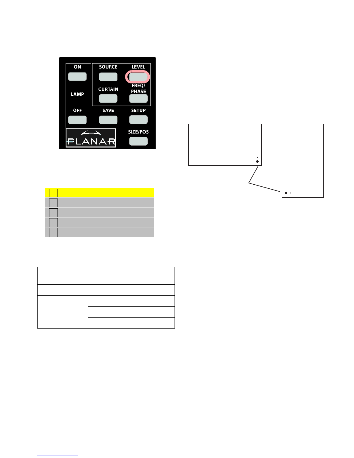
To access the Input Levels menu, on the Remote press
LEVEL:
The Input Levels menu looks different for different colorspaces. The Input Levels for Digital RGB sources is
shown below:
Input Levels
Black Level (offset)All 128
Red 128
Green 128
Blue 128
Reset Black Level to Default
The Input Levels menu for Digital YPbPr sources is shown
below:
Input Levels
Black Level (offset)All 128
Red 128
Green 128
Blue 128
Hue 128
29
Reset Black Level to Default
Page 37

30
Page 38

3.2.3 Adjusting Levels for Analog Sources
This section applies to Analog RGB (computer) pictures only. The Levels are best adjusted semi-automatically.
Why adjust levels?
For analog RGB pictures the levels for black and white
vary from one computer to another, or from one video processor to another. They even vary between video outputs
from a multiple-output video card in a computer.
Your pictures will not look their best on Bobcat X until
you adjust for these differences. This is not about adjusting
color or contrast. It’s about telling the Bobcat X what the
computer or processor means by black and by white.
Semi-automatic level adjustment
1. From the computer source, display an all-black picture.
This must come from the computer source that will be
used for the program. It does no good to use your lap-
top for this adjustment, then connect to a different computer for the program. Nor can you use the Bobcat X’s
black test pattern. (Hint: Display a black screen using
Windows Paint program.)
✎ To adjust levels for UXGA sources that will be
displayed in One to One scale mode, perform your
adjustments using Fill All scale mode and then
switch back to One to One.
2. To access the Input Levels menu, on the Remote press
LEVEL:
Input Levels
Auto Black Level (offset)
Auto White Level (gain)
Center Point 64 124 99
Black Level (offset)-All 79
Red 89
Green 67
Blue 83
White Level (gain) -All 99
Red 99
Green 99
Blue 99
31
3. In the Input Levels menu, select Auto Black Level and
press
ENTER. This menu line says “Working…” until
the process is complete.
4. From the computer source, display an all-white picture.
5. In the Input Levels menu select Auto White Level and
press
ENTER. Wait for “Working…” to disappear.
The Bobcat X is now adjusted to the black and white
levels of this computer using this video card. If you
change computers or video output cards in the computer, you must do this again.
Page 39

✎ Black Level must be done before White Level. The
black and white pictures must come from the real
source. It doesn’t help to do this with a laptop,
then plug in the “real” computer for the program.
els to the brightest and darkest pixel, respectively, in the
picture.
Advanced Options
That completes the levels adjustments. If you have more
than one computer or other analog RGB source, as might
come from a switcher, you should do this for each source
and save the configuration to a memory slot.
Manual level adjustment
1. Display an all-black picture from the source computer.
✎ You cannot make these adjustments using the
internal Test Patterns. The black/white picture
must come from the computer that will be used for
the program material. Adjusting levels with your
laptop, then connecting to the “real” computer will
not do a proper job.
2. On the remote press
LEVEL.
3. In the Input Levels menu, select Black Level and
adjust it up and down with the + \ – keys to make the
three C
ENTER POINT values go to zero. If they do not
all touch zero at the same time, use the individual colors under B
LACK LEVEL to adjust them.
✎ Do not go beyond the point where the Minimum
just goes to zero. The idea is to just touch the zero
level.
4. Display an all-white picture from the source computer.
Next, adjust White Level (gain) until the Image Maxi-
mums just go to 255. Again, do not push it up after the
maximum is 255. Just touch the 255 point. You must adjust
Brightness first, Contrast second.
If the three colors are not all at 255 (or 254), adjust them
separately.
Color Balance
Miscellaneous Options
Backlight Settings
Serial Port Settings
Auto Setup Options
Menu Options
Message in Picture
Auto Setup Options
Retry on Lost Signal
Do Black/White Levels
Do Frequency
Do Phase
Do Position
This does not work well because:
• some pictures do not contain a pure white pixel;
• some white pixels contain “spikes,” which makes them
seem brighter than they really are, resulting in incorrect
settings.
For these reasons, we recommend you leave Do Black/
White Levels unchecked.
Full automatic level adjustment
Automatic adjustment of black and white levels does not
do as good a job as manual adjustment of levels. By selecting Do Black/White Levels box in the Auto Setup Options
menu (Main Menu > Advanced Options > Auto Setup
Options), the Bobcat X adjusts White levels and Black lev-
32
Page 40

3.2.4 Adjusting Levels for Video Sources
Video sources are adjusted best if a color bar test pattern is available from the video source: the DVD or VCR
player. If not, you will have to adjust by eye and the “feel” of the picture.
Adjusting the picture
1. Select a video source in the Picture menu.
2. To access the Input Levels menu, on the Remote press
LEVEL:
Input Levels
Brightness 140
Contrast 165
Saturation 150
Hue 128
Blue Only
5. Uncheck Blue Only
✎ When a video source is selected, Auto Setup
Options is not available. Adjustments must be
made manually.
6. If the color bar pattern has a pluge, you can use it to
adjust Brightness.
Pluge
✎ These controls are also used for analog sources
when you chose YPbPr Colorspace.
Now you have two choices.
• Adjust using any picture from the video source.
• Adjust using a standard color bar pattern from the
source.
Adjusting with color bars
1. If possible, use a color bar pattern from the video
source you will use for the program material. You cannot use the color bar from the Test Patterns menu.
2. In the Input Levels menu, check Blue Only. You
should see only the alternate color bars, all of them
blue.
3. Adjust Saturation to make the outer two color bars
match. Match them in brightness; they will already
match in color.
4. Adjust Hue to make the inner two color bars match.
33
Adjust Brightness so you cannot see
the different between these two
marks,
but you can see the difference
between these two marks.
Page 41

Adjusting with any picture
This procedure must be done after you adjust color bal-
ance (page 57).
1. Choose pictures that have blacks and whites represented as well as a variety of colors.
2. Adjust Contrast, Brightness, Saturation and Hue on one
Bobcat X until it looks satisfactory.
3. Adjust all the other Bobcat Xs in the array so they have
the same values for Contrast, Brightness, Saturation
and Hue as the first Bobcat X.
Saturation
Match
Match
Match
Adjust Saturation so the outside bars match
when Blue Only is checked.
Hue
Match
Adjust Hue so inside bars match when
Blue Only is checked.
34
Page 42

3.3 Aspect Ratio Settings
The aspect ratio of any picture is its width divided by its height. W / H = Aspect Ratio
The native aspect ratio of the Bobcat X screen is 1.77,
which is sometimes referred to as 16:9. This is the WXGA
and HDTV picture format.
The aspect ratio of a picture is width divided by height:
1366 horizontal pixels, 768 vertical pixels
1366 / 768 = 1.77
Many pictures do not have this aspect ratio. Standard
television, VGA, SVGA, and XGA signals are 1.33. Movies from DVDs vary depending on the original film format,
often 1.85. The larger the number, the “wider” the picture
seems.
When the incoming picture is a different aspect ratio
from the screen, Bobcat X gives you six choices to make it
fit.
Scale Mode Settings
1. To select the scaling mode, on the remote press
The Aspect Ratio & Wall menu displays.
Aspect Ratio & Wall
Scale Mode Crop
Justify Center
Overscan 0%
Border Color Black
Wall Width 1
Wall Height 1
Unit Column 1
Unit Row 1
Wall Mode
WALL.
35
Frame Compensation
Frame Height 97 pixels
Frame Width 157 pixels
✎ If the Bobcat X does not have a Big Picture Key
installed, this menu looks different.
Page 43

2. With the selector on Scale Mode, press ENTER.
The Scale Mode sub-menu displays.
Fill All
Crop
Letterbox/Pillarbox
Widescreen (16x9)
Normal Video (4x3)
One to One
The six Scale Modes are “radio” buttons; you can
only choose one.
✎ The Scale Mode menu icons change to indicate
the effect each mode will have on the picture
based on the Justify and Scale Mode settings, and
the source resolution.
Scale
Mode
Fill All No distortion Compresses width to fit Stretches width of image Displays at native resolu-
Affect on Input Type on 4X3 Display Affect on Input Type on 16X9 Display
Standard Video or
VGA/SVGA/XGA
1080i or WXGA Computer Source
Standard Video, VGA/
SVGA/XGA, or 4X3
1080i or WXGA Computer
or 16X9 Source
tion without distortion
Fill All makes the picture fit top-to-bottom and left-to-right regardless of how this stretches or compresses the picture. Fill
All distorts the picture, when the aspect ratio of the incoming picture is not the same as the Bobcat X screen.
Crop No distortion Crops width of image;
fits height of image without distortion
Crops top and bottom of
image; fits width of image
without distortion
Displays at native resolution without distortion
Crop expands non-native aspect ratio pictures until the second edges touch the border and lets the other edges of the pic-
ture fall outside the display and get cropped
36
Page 44

Scale
Mode
Affect on Input Type on 4X3 Display Affect on Input Type on 16X9 Display
Standard Video or
VGA/SVGA/XGA
1080i or WXGA Computer Source
Standard Video, VGA/
SVGA/XGA, or 4X3
1080i or WXGA Computer
or 16X9 Source
Letterbox/
Pillarbox
No distortion Fits width of image with-
out distortion; fills height
with border
Fits height of image without
distortion; fills width with
border
Displays at native resolution without distortion
Letterbox/Pillarbox expands the picture until the first edges (top-bottom or left-right) touch the border of the display,
and then fills in the other sides with a solid color
Widescreen
Stretches width of
image. Fills Top and
Bottom with border
Fits width of image without distortion; fills height
with border
Stretches image to fill width
without affecting height
Displays at native resolution without distortion
Widescreen (16x9) forces the aspect ratio to 16 x 9 (1.77), the standard for many DVD movies. This will distort any picture other than 16X9 aspect ratio pictures. Widescreen can be used to display anamorphic DVDs on an array
Normal
Video
No distortion Compresses width to fit,
no border
Fits height and width of
image without distortion;
fills width with border
Fits height of image, compresses width and fills
with border
.
Normal Video (4x3) forces a 4 x 3 (1.33) aspect ratio, the ratio of standard television. Normal Video is used to display
YPbPr video on the analog input port. Its resolution is 720x640 which is not 4x3 but it should be displayed as 4x3 (the
pixels aren't square)
37
Page 45

Scale
Mode
Affect on Input Type on 4X3 Display Affect on Input Type on 16X9 Display
Standard Video or
VGA/SVGA/XGA
1080i or WXGA Computer Source
Standard Video, VGA/
SVGA/XGA, or 4X3
1080i or WXGA Computer
or 16X9 Source
One to
One
No distortion Fits width of image with-
out distortion; fills height
with border
Example above represents an XGA
input on an XGA
resolution unit, such
as a Puma X
(1024 x 768)
Example above represents a 1080i
(1920 X 1080) resolution
Displays image without distortion at actual size with
border on all sides
Example above represents
a VGA input
Displays at native resolution without distortion
Example above is for
1366 x 768 input on
1366 x 768 native resolution or 1920 x 1080 input
on 1920 x 1080 native
resolution
One to One maintains the original size and aspect ratio of the picture. This may leave blank areas on all four sides. For
instance, a VGA picture (640 × 480) on a 16X9 display will occupy only a small area in the center of the screen. For
UXGA sources on a 16X9 display, this will crop the picture top, bottom, and sides. The primary use of One to One is to
display the image without scaling artifacts and with minor cropping
✎ The One to One Scale Mode will produce different cropping results and the image size will be different for
each input resolution
38
Page 46

Justify Settings
Justify determines how the picture will be placed in the
wall. For a single unit, Justify determines placement on the
screen.
To p/ Le ft positions the image starting with the top, leftmost unit, then across and down. If the image is not large
enough to fill all the units, they are left blank.
Center positions the image starting with the center of
the image in the center of the wall spreading out equally to
all units. If the image is not large enough to fill all units,
they are left blank.
Bottom/Right positions the image starting with the bottom, rightmost unit, then across and up. If the image is not
large enough to fill all the units, they are left blank.
Border Color Settings
Border Color determines the color of the “extra” space
around the picture if it doesn’t fill the screen. The choices
are:
• Black
• White
•Red
• Green
•Blue
• Dark Blue
• Dark Green
•Dark Red
✎ When the Scale Mode is Fill All, the Border Color
line will be grayed out, because there will be no
border.
Aspect Ratio & Wall
Scale Mode Normal Video
Justify Center
Overscan 0%
Border Color Black
No Big Picture Key installed
39
Page 47

40
Page 48

3.3.1 Adjusting Sharpness
After you set the Scale Mode to the one you will use for the program, select the Sharpness level in the Picture
menu to reduce scaling artifacts. If you are not scaling your image, you may skip this section.
Sharpness Settings
The Sharpness setting is in the Picture menu (press
FREQ/PHASE on the remote) .
Picture
Source Digital
Colorspace RGB
Vertical Frequency (frame locked) 60Hz
Horizontal Frequency 50.00kHz
Horizontal Resolution 1366
Vertical Resolution 768
Sharpness Sharpest
There are five levels of sharpness:
•Sharpest
•Sharp
•Normal
•Soft
•Softest
From the Aspect Ratio menu (Main > Aspect Ratio &
Wall), select Scale Mode.
Aspect Ratio & Wall
Scale Mode Crop
Justify Center
Overscan 0%
Border Color Black
Wall Width 1
Wall Height 1
Unit Column 1
Unit Row 1
Wall Mode
Frame Compensation
Frame Height 97 pixels
Frame Width 157 pixels
NTER to move to the Scale Mode sub-menu. Use
Press E
the up and down arrow keys to highlight the mode you
need. Press E
NTER to select the mode...
Normal is the default, which passes the picture through
unaffected. Make any adjustments to sharpness with the
picture scaled, that is, with the Scale Mode set the way you
will use it. Use Sharpness to reduce artifacts of scaling.
✎ The Sharpness adjustments are in effect only
when the image is scaled.
41
Fill All
Crop
Letterbox/Pillarbox
Widescreen (16x9)
Normal Video (4x3)
One to One
✎ The Scale Mode menu icons change to indicate
the effect each mode will have on the picture
based on the Justify and Scale Mode settings, and
the source resolution.
Page 49

42
Page 50

3.3.2 Adjusting Position
Position moves the picture on the screen but does not move the menus.
Image Position
On the remote, press the
SIZE/POS button once to open
the Picture Position menu. The four arrow keys move the
picture on the screen.
Picture
Position
Use arrow keys to move image
Horizontal Position 168
Vertical Position 19
The numbers for Horizontal and Vertical Position refer
to the number of pixels from sync to the first displayed
pixel. These numbers get smaller as the picture moves up
and to the left.
The Horizontal Position number shows the number of
pixels from the beginning of H sync to the first active pixel.
Because there are many black pixels after H sync, this number will not be zero when the picture is at the left border of
the screen.
The Vertic al Positio n number is the number of lines
from V sync to the first active line, so it will not be zero
when the picture is at the top of the screen.
43
Page 51

44
Page 52

3.4 Tiling a Display
Whether you use Planar’s Big Picture™ or an external video processor, your goal is to make the picture fit
together properly at the edges.
Using an external processor
The processor divides a single picture into several sections and sends each part on a separate cable. Connect these
cables to the proper Bobcat X.
You can still position the picture with the Bobcat X controls, or, with most processors, position and zoom the picture with the processor controls.
Using Planar’s Big Picture™
Loop the same source through all the Bobcat Xs in a
wall (See “Connecting Picture Sources” on page 13.).
For each unit, set the Wall menu for the same wall size.
To show the same source on all the Bobcat Xs in an array
you’ll need to use an external distribution amplifier. For
each unit, set the Aspect Ratio & Wall menu for the same
array size.
Main Menu
Picture
Size & Position
Aspect Ratio & Wall
Memory
Diagnostics
Advanced Options
Program Information
Aspect Ratio & Wall
Scale Mode Crop
Justify Center
Overscan 0%
Border Color Black
Wall Width 1
Wall Height 1
Unit Column 1
Unit Row 1
Wall Mode
45
Frame Compensation
Frame Height 97 pixels
Frame Width 157 pixels
Wall Width and Wall Height are the number of units
wide and high for the picture. This may be different from
the physical array size. You could build a 4x4 array of
Bobcat Xs and use Wall Mode to put a single picture on the
four units in the upper left corner, for instance.
• Unit Column and Unit Row represent the position of
the Bobcat X in this “array.” For example, in the 4 x 3
array of Bobcat Xs shown below, unit numbering starts
Page 53

at the top left corner of the array. This unit would have
a Unit Column value of 1 and a Unit Row value of 1
1:1 2:1 3:1 4:1
1:2 2:2 3:2 4:2
1:3 2:3 3:3 4:3
• Wall Mode, when checked, turns on the Planar Big
Picture™ feature. When not checked, the unit shows
the whole picture.
✎ Each unit in an array gets the whole picture by
feeding them all with a distribution amplifier. The
Aspect Ratio & Wall menu tells the unit what
portion of the entire picture to display.
Frame Compensation
image you see is partially obscured by the frames, but your
mind assembles the image and ignores the frames.
Frame compensation allows you to mimic the mind’s
function by “hiding” portions of the picture (as if the mullions were actually hiding the image) and allow the distributed image to appear as one very large image.
When video units are used in an array, the intent is to
display a large version of an image. However, even the thinnest of mullions break up the image oddly.
One way around this is to adjust the image. Imagine
looking out a window made up of many panes of glass. The
To ensure that images containing diagonal lines remain
correctly diagonal, turn on Frame Compensation.
Depending on how closely you space the units, you must
determine how much of the picture to “hide” behind
Bobcat X’s mullions and the space between units.
WARNING
The Bobcat X generates heat. Plan your array
installation to provide adequate ventilation or
cooling to ensure that your Bobcat Xs operate
within normal usage guidelines. For more
information, see “Optimizing Your Planar Display” on page 133.
If you have any questions about your installation, consult Planar Systems for proper Bobcat X array configuration guidelines.
To hide pixels at the top and bottom of images, set
Frame Height.
To hide pixels to the left and right of images, set Frame
Width.
46
Page 54

3.5 Saving and Recalling Configurations
Some settings are saved automatically, but there are big advantages to saving a configuration manually. You can
use the 40 numbered memory “slots” to quickly save and recall a complete setup.
How automatic save works
Whatever changes you make with the remote control or
RS232 commands, these changes are saved automatically.
If you change sources (switch to another input connector)
and come back to this source, everything you did before
will be “recalled.” Things will look like they did before.
Suppose you make adjustments to an SVGA source on
Analog 1, then you feed a UXGA source to Analog 1 and
make new adjustments. Then you switch to the S-Video 1
connector and do some more setup for it.
Later you switch to the Analog 1 input again, and this
time it has the SVGA source from before. The Bobcat X
will recognize that it has seen this source before, or at least
a source with these characteristics, and will recall the
SVGA settings you established before.
This kind of recall includes Input Levels, Position, and
Frequency, but it does not include Wall Mode and any Big
Picture adjustments you made. Those need to be recalled
from memory slots.
The fastest, most efficient way to change from one source
to another, or to change a wall from individual pictures to
one big picture, is to recall a memory. All of this is saved
even with AC off.
Global storage
Some things are stored globally; that is, they stored at
the unit level and are the same for all memory slots.
• everything in the Miscellaneous menu
• everything in Auto Setup Options
• everything in Menu Options
• all the Hours menu
• all the color balance settings
How to save
See “Saving Configurations” on page 48.
How to recall
See “Recalling Stored Configurations” on page 51.
How to delete
See “Deleting a Configuration” on page 53.
What the memories store
• selected source
• resolution (and much more about the signal)
• frequency
•phase
• sharpness
• position and size (zoom settings)
• everything in the Wall & Aspect Ratio menu
• Black and While Levels for RGB sources
• Brightness, Contrast, Hue, and Saturation for video
sources
All this is stored separately for each memory slot; as an
example, you could store multiple different wall setups and
switch between them quickly.
47
Page 55

3.5.1 Saving Configurations
Bobcat X has 40 numbered memory slots; use them to save and recall settings, which is the fastest way to change
configurations.
1. Set up the Bobcat X the way you want it, including all
the adjustments listed in this chapter.
2. Press the
SAVE button twice.
The Save menu displays. This menu contains 40 numbered memory slots.
Save
1 9 17 25 33
2 10 18 26 34
3 11 19 27 35
4 12 20 28 36
5 13 21 29 37
6 14 22 30 38
4. Press
ENTER.
The Save to Slot menu displays.
.
Save
Save to Slot 1
Save Now
Name AN 1366x768
Source Analog
Colorspace RGB
Resolution 1366 x 768
Wall 2 x 2 1:1
Scale/Justify One to One / Center
Postion/Overscan 168,19 / 0%
Zoom UL/ LR +0,+0 / +0,+0
Viewport UL/LR +0,+0/ +0,+0
Frequency/Phase 1602 / 22.5°
Sharpness Normal
Black Level 63 55 57
White Level 166 170 169
7 15 23 31 39
8 16 24 32 40
3. Using the arrow keys on the remote, navigate to a slot:
• an unchecked slot number allows you to save new settings
• a checked slot has settings already saved to it. You can
overwrite what’s already saved if you wish.
5. Select Save Now and press ENTER.
48
Page 56

a) If this memory already has something stored in it,
the word
(Overwrite) appears in red on this line.
This is the only warning.
b) If the current settings exactly match what is already
in the memory, (Current) will appear in the Slot to
Recall line.
Save
Save to Slot (Current) 1
Save Now (will overwrite occupied slot)
Name AN 1366x768
Source Analog
Colorspace RGB
Resolution 1366 x 768
Wall 2 x 2 1:1
Scale/Justify One to One / Center
Postion/Overscan 168,19 / 0%
Zoom UL/ LR +0,+0 / +0,+0
Viewport UL/LR +0,+0/ +0,+0
Frequency/Phase 1602 / 22.5°
Sharpness Normal
Black Level 63 55 57
White Level 166 170 169
Save
Save to Slot (Current) 1
Save Now
Name AN 1366x768
Source Analog
Colorspace RGB
Resolution 1366 x 768
Wall 2 x 2 1:1
Scale/Justify One to One / Center
Postion/Overscan 168,19 / 0%
Zoom UL/ LR +0,+0 / +0,+0
Viewport UL/LR +0,+0/ +0,+0
Frequency/Phase 1602 / 22.5°
Sharpness Normal
Black Level 63 55 57
White Level 166 170 169
c) If neither message appears, this slot is empty.
6. Press
ENTER. Bobcat X instantly stores all the current
settings into that memory.
The name of the memory will be the default name,
which is an abbreviation of the source connector, resolution
and, if wall mode is on, wall settings.
This menu shows all the settings that will be saved. You
can’t change anything but the name in this menu. To save
immediately, press
ENTER. The appearance of this menu is
somewhat different for digital and video sources, reflecting
what is saved for them.
Changing the name of the memory slot
The default name is an abbreviated description of the
contents. In the example below, the name tells you that the
source is connected to Analog 1, which is an XGA picture.
This unit is part of a 2x2 array, and it’s the unit lower left
corner (column 1, row 2).
49
Page 57

1. If you want a more descriptive name, select Name and
press
ENTER.
A little bar appears beneath the name.
Save
Save to Slot 1
Save Now
Name AN 1366x768
Source Analog
Colorspace RGB
Resolution 1366 x 768
Wall 2 x 2 1:1
Scale/Justify One to One / Center
Postion/Overscan 168,19 / 0%
Zoom UL/ LR +0,+0 / +0,+0
Viewport UL/LR +0,+0/ +0,+0
Frequency/Phase 1602 / 22.5°
Sharpness Normal
Black Level 63 55 57
White Level 166 170 169
a) Use the + \ – keys to move the yellow spot under the
character you want to change.
b) Use the up-down arrows to change the character.
2. When you are finished, press
3. Select Save Now and press
PREV.
ENTER again.
If the memory already had data, and the only change is
to the name, you will see
(Update Name) on this item.
✎ If you use RS232 control, you can also use
commands to send a string name to a memory
slot, saving time.
50
Page 58

3.5.2 Recalling Stored Configurations
This is the fastest way to change from one configuration to another.
1. Press SAVE once to open the Recall menu.
2. Navigate to the slot you want to recall. You can only go
to slot numbers that are not empty (have checks).
Recall
1 9 17 25 33
2 10 18 26 34
slot. If the name is not the one you want, press
and choose another memory.
Recall
Slot Number 17
Recall Now
Name AN 1366x768
Source Analog
Colorspace RGB
Resolution 1366 x 768
Wall 2 x 2 1:1
Scale/Justify One to One / Center
Postion/Overscan 168,19 / 0%
Zoom UL/ LR +0,+0 / +0,+0
Viewport UL/LR +0,+0 / +0,+0
Frequency/Phase 1602 / 22.5°
Sharpness Normal
Black Level 63 55 57
White Level 166 170 169
PREV
3 11 19 27 35
4 12 20 28 36
5 13 21 29 37
6 14 22 30 38
7 15 23 31 39
8 16 24 32 40
3. Press
ENTER to open the Recall detail menu.
The name of the memory is listed here, as well as all
the important parameters (data) stored in that memory
4. To recall the settings saved to this slot, select
Now
and press ENTER.
Recall
51
Page 59

5. If this slot number has exactly the same settings are
currently being used, a (Current) message appears on
the top line.
Recall
Slot Number (Current) 17
Recall Now
Name AN 1366x768
Source Analog
Colorspace RGB
Resolution 1366 x 768
Wall 2 x 2 1:1
Scale/Justify One to One / Center
Postion/Overscan 168,19 / 0%
Zoom UL/ LR +0,+0 / +0,+0
Viewport UL/LR +0,+0 / +0,+0
Frequency/Phase 1602 / 22.5°
Sharpness Normal
Black Level 63 55 57
White Level 166 170 169
Advantages of saving configurations to memory slots
• You can compare multiple settings quickly
• You don’t have to repeat settings when comparing
entire configurations
• You can revert to a known good setting when testing
new configurations
52
Page 60
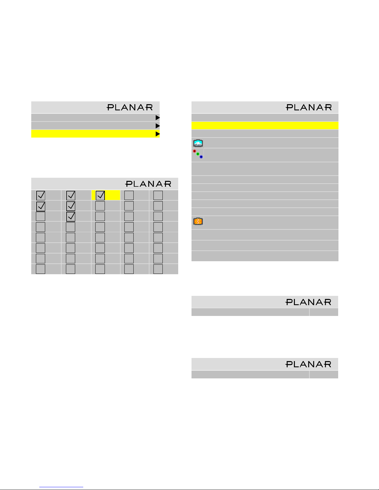
3.5.3 Deleting a Configuration
There is no particular reason to delete a configuration, because you can always overwrite it.
1. Go to the Memory menu (Main > Memory).
Memory
Recall
Save
Delete
2. Select
Delete and press ENTER.
This opens a Delete grid of 40 numbered memory slots.
Delete
1 9 17 25 33
2 10 18 26 34
3 11 19 27 35
4 12 20 28 36
5 13 21 29 37
6 14 22 30 38
7 15 23 31 39
4. In the Delete detail menu
Delete
Slot to Delete 17
Delete Now
Name AN 1366x768
Source Analog
Colorspace RGB
Resolution 1366 x 768
Wall 2 x 2 1:1
Scale/Justify One to One / Center
Postion/Overscan 168,19 / 0%
Zoom UL/ LR +0,+0 / +0,+0
Viewport UL/LR +0,+0/ +0,+0
Frequency/Phase 1602 / 22.5°
Sharpness Normal
Black Level 63 55 57
White Level 166 170 169
Delete Now is selected.
8 16 24 32 40
3. Navigate with the arrow keys to the slot you want to
delete and press
ENTER.
When navigating, you can only go to the checked numbers. All the slots with check marks have something
stored in them. The others are grayed out.
✎ The menus you’ll see will likely have different
settings than those shown in the example below.
The Wall menu item appears only if Wall Mode is
enabled.
5. Press
Are you Sure? Yes No
ENTER.
Confirm Slot Delete
1. Use the left arrow to make the Yes red and press
ENTER.
Confirm Slot Delete
Are you Sure? Yes No
✎ It is not necessary to delete the data in a memory
slot before saving new data. Saving will overwrite
the stored data. See “Saving Configurations” on
page 48.
53
Page 61
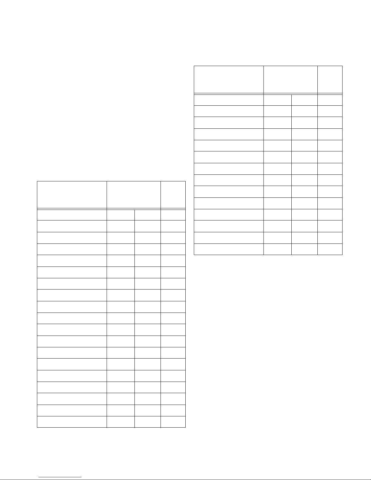
3.5.4 Memory: What Is Saved? And Where?
In the Bobcat X some parameters (values) are associated
with the mode. The mode is primarily the horizontal and
vertical resolution and the vertical frequency of the incoming source picture. It is more than this, but if you think of it
this way, you will be close enough.
Some parameters are associated with the input. The
input in this instance means the input connector: Analog 1,
Digital, Composite Video, etc.
✎ The parameters specific to Mode and Input are
saved in memory slots.
Some parameters are global, that is, they are not associated with either the mode or the input connector, and are
not saved to memory slots. They are universal.
Specific to the
Parameter
Mode Input
ASCII Response Term. x
ASCII Response Type x
Auto Codes x
Global
Specific to the
Parameter
Mode Input
Menu H Position x
Menu Timeout x
Menu V Position x
Phase x
Plug and Play (EDID) x
Position, Horizontal x
Position, Vertical x
Resolution, Horizontal x
Resolution, Vertical x
Retry On Lost Signal x
Saturation x
Sharpness x
Unit ID x
Global
Auto Backlight On x
Baud Rate x
Black Level: R, G, & B x
Brightness (video) x
Color Balance (all values) x
Colorspace x
Contrast (video) x
Curtain Pattern x
Do Black/White Levels x
Do Frequency x
Do Phase x
Do Position x
Frequency x
Group ID x
Hue x
Justify x
White Level: R, G, & B x
Memory
The Bobcat X remembers the last 10 modes it received
and all the mode parameters associated with them.
Switching modes
For instance, suppose you set up the Black and White
Levels for a 1024x768 @ 65Hz vertical from a computer
connected to Analog. Then later, using the same input connector but a different computer you set up the Bobcat X for
a 1600x1200 @ 60Hz. You re-adjust the Black and White
Levels, because they are different.
Still later you plug in the first computer with its
1024x768 @ 65Hz picture. Immediately, the Bobcat X recognizes that it has seen this signal type before, and it recalls
the Black and White Levels from its internal memory.
It does not Do Frequency or Phase or anything else,
because it recognizes that this input was used before, and
the previous settings are probably correct.
Possible issue with Mode specific memory
Suppose that after setting up the 1024x768 and
1600x1200 pictures, you connect a third computer that is
54
Page 62

1024x768, but it has a different requirement for Black and
White Level. In this case, the Bobcat X would use the
default values for these levels.
To prevent this from happening, use the memory slots to
save this specific configuration as described in “Saving and
Recalling Configurations” on page 47.
Switching input connectors
Now suppose you use to bring in a picture that uses the
component YPbPr video. You change the Colorspace setting to YPbPr. If you switch back to Analog in the Picture
menu, the Bobcat X switches back to the RGB Colorspace,
because Colorspace is specific to the input connector.
Possible issue with Input specific memory
What happens if you switch back to Analog and the picture there is YPbPr? The Bobcat X has no way to know
this, no way to detect the difference between RGB and
YPbPr, so it will use the wrong Colorspace.
To prevent this from happening, use the memory slots to
save this specific configuration as described in “Saving and
Recalling Configurations” on page 47.
Global parameters
In none of the examples above does the Bobcat X try to
change the Baud Rate or the Color Balance values, because
these items are saved globally.
55
Page 63

56
Page 64

3.5.5 Adjusting Color Balance
Color Balance is used to match the colors of adjacent displays when several Bobcat Xs are arranged in an array.
You may also use it to adjust the color of a single display.
For one Bobcat X only
If you have only one display, the Color Balance controls
can be used to set the color temperature of the single display.
To access the Color Balance menu, on the Remote press
MISC once :
Color Balance
Color Temperature 8500K (Cool)
White Balance - All (Clipboard)
Red 100 (100)
Green 100 (100)
Blue 100 (100)
Gray Balance - All
Red 7 (7)
Green 7 (7)
Blue 7 (7)
Test Pattern Off
Hide Menu
Copy to Clipboard
Recall From Clipboard
Reset to Defaults
Understanding Color Temperature
Different "Pure white" light sources do not always have
the same color. For instance, light from an incandescent
bulb is much more yellowish than light from direct sunlight. "Color Temperature" is a way of measuring these
color differences. In general higher color temperature numbers are more bluish or "cooler". You may have a reason for
wanting your unit to be a specific color temperature. For
instance, if you are using the Bobcat X in a television studio where you will be videotaping the content, you will
want a low color temperature. The default color temperature for the Bobcat X is 8500k. This is the native color temperature of the LCD panel. You may choose a different
color temperature by setting it in the Color Balance menu.
Adjusting Color Temperature
Select Color Temperature in the Color Balance menu
and select from 3200°K (Warm), 5500°K, 6500ºK, and
8500°K (Cool).
Each of these selects a set of White Balance values to
give the picture a warm (3200K) to cool (8500K) appearance.
To adjust an array of Bobcat Xs for Color Balance
The object of color balancing is to make the individual
units in an array show the same colors. When we see a yellow car move across a video array from one display to
another, we want it to have the same color for the whole
trip, not change from yellow to tan to orange.
The displays naturally have slightly different colors
from one display to the next, because of slight variations in
the backlights and LCDs. This cannot be avoided, but we
can compensate for it with color balancing.
Color balancing is subjective. It may seem strange at
first, but it gets easier with practice. Fortunately, you don't
have to match all the colors; you only have to match whites
and grays.
When you make all the displays look the same with
White and Gray, all the other colors will look the same. It is
not necessary to achieve a perfect white or a perfectly colorless gray. It is only necessary that all the displays look
alike when they display white and gray.
57
Page 65

CAUTION
Never try to match the colors of the display
units with the Black and White Level controls
or with the Video Controls. You will not like the
results if you do.
CAUTION
If you are color blind, even a little bit, do not do
color balancing. Have someone else color balance the wall.
Color Balancing
a) Open the Color Balance menu on all displays in the
array. (
MENU > ADVANCED OPTIONS > COLOR BAL-
ANCE).
✎ If the array has never been color balanced, make
sure you start with the same color temperature
setting on each unit. If you are not interested in
achieving a specific color temperature, use the
default of 8500K, which is the brightest. If the unit
has been color balanced before, it will display
C
USTOM in its color temperature setting, because
the balance values don’t match any of the pre-set
color temperatures.
1. Turn on all the units in the array and let them warm up
for at least five minutes. The backlights must be thoroughly warm before you color balance.
2. Open the Backlight Control and Status menu (
> A
DVANCED OPTIONS > BACKLIGHT CONTROL).
Backlight Control
Auto Backlight on
Turn Backlight off with no Source (DPMS)
DPMS Delay 1 hr
Ambient Light 239 Lux
Backlight Control Mode Auto
Backlight Intensity 100
Ambient Threshold 99Lux
Low Intensity 30
MENU
a) Set Backlight Mode Control to Manual.
Backlight Control
Auto Backlight on
Turn Backlight off with no Source (DPMS)
DPMS Delay 1 hr
Backlight Control Mode Manual
Backlight Intensity 100
b) Highlight Test Pattern and use the left-right arrow
keys until it says White.
✎ Always use the internal Test Patterns for color
balancing, not an external pattern.
4. When all displays are white, find the least bright display in the array. This will be the “baseline” display,
and you will not adjust it. All other displays will be
adjusted to this baseline display.
✎ Why pick the “least bright” display? Why not pick
the brightest and adjust to it? When the White
value is 100, the display is as bright as it can get.
You are adjusting for slight variations in backlight
brightness.
5. Choose a display next to the baseline display and adjust
its White values (red, green, and blue) to make it match
the baseline display. Concentrate on the center of the
displays, not the adjacent edges. (If you can’t bring theses settings down to match the baseline, maybe you
didn’t choose the darkest display.) Do not adjust the
Gray values at this time.
6. Continue with other adjacent displays until all the displays have the same appearance when white. Be careful
not to change the values of displays once you are satisfied with them. Use Hide Menu to keep from setting
other displays and allow you to see more of the white
field. To unhide the menu, press E
NTER
b) Set (or confirm) Backlight Intensity to 100%.
3. For each Bobcat X in the array, do the following:
✎ The menus will automatically turn off after a time
determined in Menu Options (
Options > Menu Options > Menu Timeout). If
Menu Timeout is 0 (zero), the menus stay up
indefinitely.
MENU > Advanced
58
Page 66

7. When all displays look the same for White, choose the
Gray test pattern in all displays.
8. Choose any display as the new baseline display. It does
not need to be the baseline display you used for White.
9. Adjust all the displays in the Gray part of the Test Patterns menu until they match the baseline display. Do
one display at a time. Again, match the center part of
the picture, not the edges.
10. When all displays match in Gray, close all the menus.
The test pattern automatically turns off.
Tips for color balancing
• Copy to Clipboard will save all the current settings to a
temporary memory. You can then make more adjustments to see if it gets better or worse. Recall from Clipboard will restore these saved settings. The clipboard is
only for testing. These values are not saved when AC
power is off.
Color Balance values are saved for all input sources in
the same memory location. Color Balance is the same for
all sources.
100
Bright
Changes in the
White value moves
this end point.
31
bars have colored bulbs at each end to tell you what the
effect will be of moving a color toward that end.
• Stand back from the display array and directly in front
of it to get the overall view.
• Small changes are difficult to see at first, particularly
with White. Change the value by 4 or 5 steps to see the
difference. If you are going the wrong way, go back and
move it 4 or 5 steps in the other direction. If neither of
these bring you closer to a match, try another color.
• When you don’t know which color to change, pick one
at random and change it 3 or 4 steps. The result will be
either better or worse. If worse, go the other way with
that color. If that is also worse, put this color back
where you started and to the same with another color. If
everything you do makes the match worse, you must be
close to the ideal point.
• You may find it easier to color balance units using Cube
Control 2, a software utility available from Planar’s
website.
Dark
Changes in the White values
affect the Gray values.
0
Output brightness
Black
Changes in the Gray values do
not affect the White values.
Changes in the
Gray value move
Output brightness
this mid point.
Input Signal
15
0
Input Signal
White
• Removing red has the same effect on hue as increasing
blue and green together. The Color Balance menu slider
59
Page 67

60
Page 68

3.5.6 Zoom and Position
Zoom adjusts the edges of the picture to make it fit with the other pictures in an array.
Zoom
Zooming is used mainly to make the edges of a large
picture—one that covers many Bobcat X screens—fit each
other side-to-side and top to bottom.
To access the Zoom menus, on the remote press
POS twice to open the Zoom Top & Left menu, and press
SIZE/POS a third time to open the Zoom Bottom & Right
menu.
You may zoom the sides larger up to +100 pixels in each
direction. You may also zoom the sides smaller up to –100
pixels, but only if that side is not the edge of the overall picture. An example may help make this point more clearly.
This is the original picture from the source.
SIZE/
Unit Y cannot be zoomed in at the bottom, but it can be
zoomed in from the right (– ) because there is more picture
out there. Of course, the center unit—Column 2, Row 2—
can be zoomed in any direction.
Zoom menu entries
• Image Resolution is the resolution of the source pic-
ture.
• This Unit is the number of pixels this unit is using of
all the incoming pixels, followed by the size of the
array (from the Wall & Aspect Ratio menu) and the
Column and Row of this unit.
Unit X
The picture is cropped and there is some extra picture to
the right, off the screens. All the units can be zoomed out
(+) to make the picture larger in each direction.
Unit X cannot be zoomed in (–) at the bottom or the left
side, because there is no more picture to pull onto the
screen.
61
Unit Y
Page 69

Zoom Top & Left
Arrows move top and left
0
0 0
0
LCD Resolution x
This unit x
Zoom Bottom & Right
Arrows move bottom and right
0
0 0
0
LCD Resolution x
This unit x
62
Page 70

3.5.7 Viewport Adjustment
The Viewport menus adjust the image on the LCD.
What is Viewport?
The Viewport menu (Main > Size & Position > Viewport) adjust the number of pixels actually used on the LCD.
You can’t increase this number, naturally, but you can
reduce it.
• Image Resolution shows the resolution of the image.
This has nothing to do with the resolution of the source
picture.
• Viewport shows the number of LCD pixels being used.
Main Menu
Picture
Size & Position
Aspect Ratio & Wall
Memory
Diagnostics
Advanced Options
Program Information
(
Size & Position
Picture Position
Zoom Window Top & Left
Zoom Window Bottom & Right
Viewport Window Top & Left
Viewport Window Bottom & Right
Reset All Windows to Default
Viewport Top & Left
Arrows move top and left
0
0 0
0
LCD Resolution x
Viewport x
Viewport Bottom & Right
Arrows move bottom and right
0
0 0
63
0
LCD Resolution x
Viewport x
Page 71

64
Page 72

3.6 Advanced Options
Advanced Options controls some settings that may not be needed in the initial configuration.
Some options on the Advanced Options menu (Main >
Advanced Options) are covered in other sections or chap-
ters of this manual:
• Color Balance: see “Adjusting Color Balance” on
page 57
The remaining options are covered later in this section.
Main Menu
Picture
Size & Position
Aspect Ratio & Wall
Memory
Diagnostics
Advanced Options
Program Information
Advanced Options
Color Balance
Miscellaneous Options
Backlight Settings
Serial Port Settings
Auto Setup Options
Menu Options
Message in Picture
• Miscellaneous Options: see “Miscellaneous Options”
on page 68
• Serial Port Settings: see “Serial Port Settings” on
page 71
• Menu Options: see “Menu Options” on page 67
65
Page 73

3.6.1 Auto Setup Options
Auto Setup Options sets what will happen automatically and what will not.
To access the Auto Setup Options menu, on the remote,
press
MISC five times.
Each of the “switches” in Auto Setup Options can be
turned on or off by selecting it (using the up-down arrows)
and pressing
When the box is checked, the action will occur under
these circumstances:
• When a new source is detected that has not been
detected before. (see “About the input memories” on
page 66 and “Input system caches” on page 73.)
• When you press the
ENTER.
SETUP button.
(see “Adjusting Levels for Analog Sources” on page 31) so
leave this unchecked.
Do Frequency and Do Phase find the frequency and
phase (separately) of the computer picture and adjust to
them. This works best on a picture that has lots of sharp
changes in brightness, such as text (adjacent white and
black pixels).
Do Position centers the picture on the screen.
Setup button
Press the
processes.
SETUP button on the remote to start the “Do”
Retry on lost signal occurs only when the present signal
(picture) disappears or changes in some way. If this item is
not checked, the Bobcat X will not try to sync to a new signal. Keep this menu item checked.
Note that searching will not happen just because the picture goes black. Black, from video or from a computer, is a
valid picture. The signal itself (the sync pulses) must be lost
to trigger a search.
The several Do items in this menu will, if checked, happen
in these situations:
• If a new signal is acquired, either through a search to a
different connector or because source picture changed
modes, such as from WXGA to UXGA, each of the
checked items occurs in the order listed in the menu.
• When you press the
of the checked actions occurs in the order given in the
menu.
Do Quick Black/White Levels searches for the brightest and darkest pixels in the picture and adjusts to these.
Black and White Levels are best done semi-automatically
SETUP button on the remote, each
Each Do that is checked will begin, one at a time,
until all are adjustments completed.
About the input memories
The Bobcat X has a ten input memories for storing the
most recent attributes of the pictures it displays. When a
new picture arrives that is near enough to a previous type, it
uses the stored attributes rather than automatically adjusting brightness, contrast, frequency, etc.
For example, suppose the Bobcat X sees an analog
WXGA picture and auto-adjusts everything in the Auto
Options Menu. Then you change the Brightness and Contrast. Then you change computers and feed in a UXGA picture.
If you now switch back to the computer with the WXGA
picture, Bobcat X will use the Brightness, Contrast, as well
as other settings, from the last time it saw a WXGA picture.
✎ Aspect Ratio is specific to the source, which
means it applies to all modes. It does not change
when the system recalls a memory from cache.
66
Page 74

3.6.2 Menu Options
Menu Options moves the menus to other places on the screen.
To access the Menu Options menu, on the remote press
MENU and from the Main menu, select Advanced Options
> Menu Options.
These controls move the menu to a different position on
the screen or rotate it for Portrait orientation. Also, the
Menu Timeout is set here.
Menu Options
H Position 100
V Position 50
Menu Timeout Never Time Out
Rotate Menu None
H Position moves the menus (all of them) left and right on
the screen. Use the left and right arrow keys to increase or
decrease the distance from the left side of the screen to the
left side of the menu. The number indicates the how far
across the screen, in percent, the menu starts.
V Position moves the menus up and down. Use the left
and right arrow keys (on the up-down keys) to move the
menu. The number indicates how far down the screen the
menu is in percent. It is not possible to move the menu to
the bottom of the screen.
Menu Timeout determines how many seconds the menu
will stay on the screen without any activity. Never Time-
out means the menus will not automatically disappear. The
maximum time is 60 seconds. The shortest possible time is
2 seconds. The default value, if you have never changed
Menu Timeout, is Never Timeout.
Rotate Menu makes the menus readable when the
Bobcat X is arranged in portrait or landscape orientation.
✎ Rotate Menu does not rotate the picture. It only
arranges the menus so they read the same way
the picture does. To use the Bobcat X in portrait
mode, your source image must be rotated.
67
Page 75

3.6.3 Miscellaneous Options
This menu holds several unrelated settings.
To access the Auto Setup Options menu, on the remote,
press
MISC twice.
Curtain Pattern determines what the screen will show
when there is no source picture. You have a choice of several solid colors or the logo.
Auto Codes when checked, automatically turns on the onscreen code LED indicator when there is an error. The LED
will start blinking on the screen immediately when any
event occurs that forces the backlights off.
Plug and Play (EDID Enable)
For Plug and Play and EDID, see the full discussion in
“EDID: What It Is and How It Works” on page 135.
Preferred Source Detection
Analog computer video cards provide only vertical and
horizontal frequencies. Sometimes, this is not enough
information. Bobcat X receiving such “ambiguous” signal
modes, in certain cases, could misinterpret the resolution to
be any of three different modes. For example, 1024 x 768,
1280 x 768, and 1360 x 768 all have the same respective
horizontal and vertical frequencies but represent different
aspect ratios, 4 x 3, 15 x 9, and 16 x 9, respectively. By
specifying the correct source detection mode, Bobcat X can
correctly interpret the signal and display the incoming
image in the proper aspect ratio. The native aspect ratio of
Bobcat X is 16 x 9, and the default resolution is1366 x 768.
time, only the even number lines of image are transmitted
to the display. At the next moment (usually 1/30 or 1/25 of
a second later) the odd numbered lines are transmitted.
These two moments in time are known as fields. On CRT
television sets, the even field persists on the phosphor long
enough so that by the time the odd field gets there, our eyes
put it all together into one picture. On digital displays, the
electronics reassembles the odd and even fields together
into one image to display every sixtieth (or fiftieth) of a
second. If the image is static, such as with computer graphics, it is quite simple to put the fields back together. However, if the image is moving, it can cause problems because
an image will have moved from the time the even lines
arrive to when the odd lines arrive. A special piece of electronics known as a deinterlacer can analyze whether an
image is moving or stationery and use mathematical algorithms to put the two image fields together in the best way.
The Bobcat X has deinterlacer electronics to take care of
standard definition television signals. However, it does not
have deinterlacer circuitry for high definition television
(1080i). The “HD Interlaced Content Motion” control gives
the regular electronics some help in determining how to put
together the two fields if you are viewing 1080i. Keeping
this setting at “Normal” works best for most images. This
will assume the image has no fast motion. The only time
you will see a problem with this setting is if you are at
native resolution (i.e. you are using a Baycat X or your
scale mode is set to one to one on a Bobcat X). In that case,
you may see something of a “zipper” effect on the edge of
moving objects. To get rid of this, change the setting to
“Rapid”. However, if you do, you will probably see static
images flickering slightly (known as “twittering”).
✎ Another alternative to minimize both effects is to
keep the setting at Normal and set overscan (in
the Aspect Ratio menu) to 1%. This will turn on the
scaler and minimize the zipper effect.For more
information about the Miscellaneous options, see
“Advanced Options > Miscellaneous Settings” on
page 110.
HD Interlaced Content Motion
HD Interlaced Content Motion is a control you probably
won't need to touch. Here is an explanation of it.
Some video signals, most notably those made for television, are what is known as “interlaced”. At one moment in
68
Page 76

3.6.4 Backlight Control
Backlight control can automatically adjust the screen brightness as ambient light conditions change.
To get to the Backlight Control menu, go to Main Menu >
Advanced Options > Backlight Settings.
Main Menu
Picture
Size & Position
Aspect Ratio & Wall
Memory
Diagnostics
Advanced Options
Program Information
Advanced Options
Color Balance
Miscellaneous Options
Backlight Settings
Serial Port Settings
Auto Setup Options
Menu Options
Message in Picture
Backlight control has two options: automatic and manual. In the manual mode, you adjust the backlight brightness to suit ambient conditions that are not likely to change.
In the automatic mode, you let the ambient light determine the image brightness. This is useful when the
Bobcat X is in a location that sometimes has daylight
which, of course, varies.
When there is more light in the area of the Bobcat X, the
screen will have to be brighter to see it clearly, and the
backlight intensity will be 100%. When there is less ambient light, the screen can be darker and still be read easily.
This is the low intensity setting which is a percentage (30%
to 100%) of the maximum backlight brightness.
The look of the Backlight Control menu depends on
whether it is in manual or auto mode.
Auto backlight control
Set the Backlight Control Mode to Auto.
Backlight Control
Auto Backlight on
Turn Backlight off with no Source (DPMS)
DPMS Delay 1 hr
Ambient Light 239 Lux
Backlight Control Mode Auto
Backlight Intensity 100
Ambient Threshold 99Lux
Low Intensity 30
1. Set the Ambient Threshold to a ambient light level at
which the backlight switches to low intensity. Thus, if
the ambient light drops, the backlight dims.
2. Set the Low Intensity at the level (in percent of maxi-
mum) you want the backlight to have when the ambient
light falls below the threshold.
The Ambient Light at the top of the menu measures the
ambient light in Lux. As long as this number is above the
Ambient Threshold number, the backlight will be 100%.
✎ Ambient Light is a relative value, and is pertinent
only to the Bobcat X. It is not an absolute value.
You may get different ambient light values with a
handheld light meter.
When the Ambient Light is below the Ambient
Threshold, the backlight dims to the Low Intensity set-
ting. Bobcat X has a nominal time delay of three minutes
before changing light levels. This time delay prevent flickering if the ambient light level is near the Ambient
Threshold.
69
Page 77

Manual backlight control
This mode is useful when the Bobcat X is in a room with
no outside windows and unchanging ambient light levels.
Set the Backlight Control Mode to Manual.
Backlight Control
Auto Backlight on
Turn Backlight off with no Source (DPMS)
DPMS Delay 1 hr
Backlight Control Mode Manual
Backlight Intensity 100
Adjust the Backlight Intensity to comfortable bright-
ness. A lower brightness will increase lamp life.
CAUTION
Changing a failed backlight is a job for a qualified service technician. It is done at the factory,
not in the field. Contact your Planar dealer.
For more information about these settings, see “Back-
light Control Menu Options” on page 113.
70
Page 78

3.7 Serial Port Settings
This applies only if you use RS232 commands to control the Bobcat X.
If you wish to control Bobcat Xs remotely with RS232
commands from a computer, read this section. Otherwise,
skip it.
Bobcat Xs can be linked together for RS232 using
straight-through 8-conductor cable with RJ-45 connectors.
This is the common type of LAN connection cable, not
null-modem, sometimes call Cat-5 cable. For more information, see “Connecting RS232 Communication” on
page 19.
RS232 is also used to upgrade the firmware of the unit.
RS232 IDs
Each unit in the loop must have a unique RS232 ID. Open
the Serial Port Settings menu for each unit.
To access the Serial Port Settings menu, on the remote,
press
MISC four times.
that have Group ID 8 and any Unit ID will execute the command.
Addressing Bobcat X
Part of the RS232 command will be an address. This
address may take several forms. For example, suppose we
have 8 units in one area divided into two groups. We might
set the ID s of the units like this:
Group ID Unit ID
A1
A2
A3
A4
B1
B2
B3
B4
With this scheme, we have four ways to address these
Bobcat Xs:
Serial Port Settings
Group ID 1
Unit ID 1
ASCII Response Type Symbolic
ASCII Response Terminator CR
Baud Rate 19200
In the Serial Port Settings menu, you specify an ID that
is unique for each Bobcat X in this RS232 loop.
The ID is in two parts, Group ID and Unit ID. Each of
these has a range of 0–9, A–Z. This range results in 1296
possible addresses.
You can group the Bobcat Xs by using the same letter or
number of the Group ID, such as 8. In this way you can
address the group as 8*, and all the Bobcat Xs in the string
71
Type of
Addresses
A3
B4
etc.
** All Bobcat Xs in this RS232 loop will obey
*4 Both the Bobcat Xs whose IDs end in “4”
B* All four Bobcat Xs in Group B will obey the
Only the specific Bobcat X addressed will
obey the command. Also, the Bobcat X will
respond to the host computer.
the command
will obey this command
command
Affect on Bobcat X
Response type and terminator
The ASCII Response Type determines what type of
data will be returned to the computer. For human readable
text in a serial program choose Symbolic. For computerread data you can use Numeric or Data Only.
Page 79

The ASCII Response Terminator will be determined
by what your serial program wants to see at the end of
every transmission from the Bobcat X.
Baud Rate must be the same as that used by the con-
trolling computer. The baud rate is not automatically set, as
it is with modem communications. It must be manually set
here and at the computer to match each other.
✎ For firmware upgrades, you don’t need to adjust
the baud rate.
Diagnostics for RS232
To view RS232 port status, on the remote, press
MONITOR
twice.
The Serial Port Status RS232 menu lists items that
concern RS232. For more information, see “Advanced
Options > Serial Port Settings” on page 114.
Controlling with RS232 commands
The RS232 protocol—the “rules” for controlling
Bobcat Xs with RS232 commands—are given in a separate RS232 Control document. For more information
about downloading documents from Planar’s website,
see “Downloading additional documentation and firmware” on page 145.
72
Page 80

3.8 Other Operations
To “disable” the remote control
To prevent unauthorized use and adjustment of the
Bobcat X, either hide the remote or disable the remote control function with an RS232 command. For more information, see “Controlling with RS232 commands” on page 72.
Input system caches
Settings (position, aspect ratio, brightness/contrast,
color balance) are saved automatically 5 seconds after you
make a change. The system caches the last ten settings.
Whenever a picture is shown from a new source with the
same resolution as a previous picture, the system recalls the
previous settings rather than readjust everything. This happens regardless of the check marks in Auto Adjust
Options. (See also “Auto Setup Options” on page 66.)
For example, suppose you display an NTSC picture in
the composite input and set the Aspect Ratio and Position
to your liking. Then you feed in a composite PAL picture
and set a different Aspect Ratio and a different Position. If
you then feed in a new NTSC picture, the previous NTSC
picture’s settings for Aspect Ratio and Position will be
used.
73
Page 81

74
Page 82

4.1 Cleaning the Screen
Clean the screen with a soft cloth or lint-free paper towel and a mild cleaning solution.
Cleaning products and how to use them
For protective glass and the LCD screen itself, a foam
spray cleaner seems to work well. It’s is sold under different names in different parts of the world. It is available
from many janitor supply companies or building maintenance supply companies. Ask for
• Claire #50 glass cleaner, or
• Sprayway #50 glass cleaner
It is probably sold under a local name, but it all comes
from one company. If you ask for either of the two names
above (it is sold under both), you will get this cleaner under
the local name.
This cleaner is good on glass.
Spray it on the protective outer glass, but not on the LCD
itself. For LCDs, spray it on the cloth, not the screen.
CAUTION
Prevent liquid from running down the screen
and leaking into the interior of the Bobcat X.
Spray liquids on the cloth or towel, not directly
on the LCD.
Paper towels tend to leave lint. A better paper towel for
cleaning is Scott
paper towels are generally available at auto parts stores,
home fix-it stores, and hardware stores.
®
Shop Towels. These blue, lint free,
Wipe the screen gently with a lint-free cloth or lint-free
paper (see Cloth below). Turn the cloth over to the dry side
and continue wiping to take up the haze.
• Glass Wax™ is another good cleaner for mirrors and
glass screens, but it does not work well on acrylic
screens. It is a liquid in a can. You spread it on, let it
dry, then wipe it off.
• Windex™
screen. (See Warning above.)
Cloth to use
White cotton cloth is better for cleaning than colored
cloth. The dyes in some colored cloth tend to make it less
absorbent.
works well, too. Just don’t spray it on the
CAUTION
If you use a cloth towel, be sure it is clean. If
the towel was used to clean counter tops or
anything else, it may contain grit which could
scratch the protective glass.
75
Page 83

76
Page 84

5.1 Basic Bobcat X Troubleshooting Steps
The Bobcat X is very simple to troubleshoot because there is very little that can malfunction
If your screen is black
Do This Result Explanation / Further Action
Step 1. On the remote, press MONITOR
Step 2. On the remote, press CURTAIN.
Step 3. On the remote, press MONITOR
twice.
Step 4. Check Power cable is connected and power rocker switch is ON
If your screen is a solid color, but not black
A menu appears The source is black. On the remote
SOURCE to change to different
press
source
If you know the source is not black, go
to Step 2.
No menu appears The backlights may not be lit. On the
remote, press O
If the screen is still black, go to Step 2.
No menu appears and no flashing
lights
The correct source appears If the correct source did not appear, go
The Test Patterns menu appears Check that no test patterns are
Reconnect cable or turn on unit If none of these steps have resolved
Go to Step 4.
to Step 3.
selected. If a test pattern is selected,
move the selector to None and press
ENTER. For more information, see “Test
Patterns” on page 83
the problem, contact Planar Technical
Support.
N.
Do This Result Explanation / Further Action
Step 1. On the remote, press
CURTAIN.
Step 2. On the remote, press
MONITOR twice.
77
The correct source
appears
The Test Patterns
menu appears
If the correct source did not appear, go to Step 2.
Check that no test patterns are selected. If a test pattern is
selected, move the selector to None and press
more information, see “Test Patterns” on page 83
If no test pattern was selected, go to Step 3.
ENTER. For
Page 85

If your screen is a solid color, but not black (Continued)
Do This Result Explanation / Further Action
Test Patterns
None Custom Color
White Gray Scale Grid
1mp
Red Red Scale
Green Green Scale 4x4 Checkerboard
Blue Blue Scale Uniformity
Black Colors Focus
Gray Color Bars Logo
Alignment Dashes
Step 3. Check to see if the source
is a solid color.
If the source is not a solid color and none of these steps have resolved the problem,
contact Planar Technical Support.
If your picture is visible, but something is wrong with it
Symptom Possible Cause Explanation / Further Action
Image is rotated Check your source. The Bobcat X has no way of rotating images.
Picture has a black edge Picture is not positioned correctly. Use the Picture Position menu to adjust it
(see “Adjusting Position” on page 43)
Check LCD alignment (see “Aligning the
LCD” on page 51).
Check LCD size (see “Adjusting Focus and
Image Size” on page 53).
Picture has a black or colored edge
Picture is too large or too
small
The source has a black edge
Wall Mode is turned on and the picture is not
the same aspect ratio as the wall. The edge
color is determined by the Border Color in
this menu
This could be a zoom adjustment, particularly
if you are using Planar’s Big Picture™
Check the Aspect Ratio and Wall menu (see
“Aspect Ratio Settings” on page 35)
Check the two Zoom menus and set them
both so you see a zero on all four sides. Then
check the two Viewport menus and see that
they read zero on all four sides (see “Zoom
and Position” on page 61)
Picture is noisy
Cable from source is poor quality or too long Use a different cable
Picture has horizontal or
vertical streaks
Poorly adjusted Phase and/or Frequency Only analog computer signals may need this
adjusted. This can be done automatically by
pressing S
ETUP on the remote.
78
Page 86

If your picture is visible, but something is wrong with it (Continued)
Symptom Possible Cause Explanation / Further Action
Colors are wrong Input Levels must be adjusted For analog computer sources, see “Adjusting
Levels for Analog Sources” on page 31. For
digital computer sources, see “Adjusting Levels for Digital Sources” on page 29
For further suggestions, see “Image Problems” on page 141
Bobcat X doesn’t respond to remote control
Possible Cause Possible Resolution
IR response disabled via RS232 Re-enable IR response using RS232 commands
Remote batteries are dead or improperly installed Replace or reinstall batteries
Remote was not aimed at the IR receiver The IR receiver is in the lower right corner (in landscape
mode; in portrait mode, it is in the lower left corner) of the
screen bezel behind a small hole
Something is blocking the IR receiver Remove the obstruction
If RS232 communication does not work
See “Basic RS232 Troubleshooting” on page 143.
Unsure what’s wrong?
See “Reading the Status Menus” on page 81 and “Reading
the LEDs” on page 137.
79
Page 87

80
Page 88

5.2 Reading the Status Menus
The Status menus show lots of information about the current state of the Bobcat X.
Unit Status menu
To display the Unit Status menus, on the remote press
MONITOR.
Unit Status
Bobcat X/L 1366 x 768
573-2400 Rev 1.2
Asset Tag:
Backlight Status OK
Internal Temperature: 32ºC
Mode ID: 31 HPer: 3178 VLines: 525
Unit Status
• Backlight Status—shows OK if the electronics mod-
ule detects that both banks of backlights are functioning
normally. Shows Failed if one or both of the backlight
banks is not drawing the correct amount of current
• Internal Temperature—the current internal tempera-
ture at one point on the backplane of the LCD panel.
For more information, see “Internal Temperature” on
page 98.
• Fans—current state of each fan. When any fan fails, the
backlights go off and you can’t see this menu.
• Interlock—whether interlocks are Ok (closed) or an
interlock is open. When any interlock is open, the backlights go off, and you can’t see this menu.
• Last Fault—Last Interlock event and the time it
occurred. This menu shows that the last event to turn
off the backlights was that an interlock opened. In the
example above, this happened 300 hours and 50 min-
utes ago in System Time. (System Time is accumulated
as long as the electronics module is on.)
Serial Port Status menu
Press
MONITOR again to display the Serial Port Status
Menu. You can go directly to either of these menus from
the main menu. Neither of these menus have any control
over the Bobcat X, so there is no highlight selector in any
of them.
• Commands Received—the number of individual com-
mand strings received by this unit.
• Replies Sent—the number of individual reply strings
sent by this unit.
• Last Packet Type—Type of command most recently
received, usually Operation.
• Last Packet Address—Type of address on the last
packet received:
• Global—sent to more than one unit, either all of
them or a group of them that included this one.
• This Cube Alone—sent the this unit exclusively,
and this unit should have sent a response.
• Not This Cube—sent to another unit or units, but
not this one.
• Not Addressed—command had no address, so
only the first unit in the serial string could have
acted on the command.
• Most Recent—The hex and ascii data most recently
received. This may not be a complete command string,
but just the tail end of it.
81
Page 89

Setup Summary
The Setup Summary menu (Main > Diagnostics >
Setup Summary) displays the current state of the
Bobcat X.
Setup Summary
Source Analog
Colorspace RGB
Resolution 1366 x 768
Wall 2 x 2 1:1
Scale/Justify One to One / Center
Postion/Overscan 169,20 / 0%
Zoom UL/ LR +0,+0 / +0,+0
Viewport UL/LR +0,+0/ +0,+0
Frequency/Phase 1602 / 22.5°
Sharpness Normal
White Balance 100 100 100
Gray Balance 7 7 7
Slot 9 Group B Unit 2
Although this looks similar to the information as the
Save and Recall menus, the values may not be the same as
in a numbered memory. You, or someone else, might have
changed something since a memory was recalled. This is
the state of the display right now.
Setup Summary shows the current Color Balance settings, which are the ones in the global memory. (Color Balance settings are not saved in individual numbered
memories.)
The look of this menu varies depending on the currently
selected source.
82
Page 90

5.3 Test Patterns
These are used for testing and troubleshooting.
Possibly the most important test pattern is None. This is the
one that allows the source picture to show on the screen.
All other patterns block the program picture.
All test patterns are full screen. Aspect Ratio has no effect.
To tu r n o n a Tes t Pa t ter n
1. Press
MONITOR three times.
2. Select the pattern with the arrow keys. Move between
columns using left-right arrow keys; up-down arrows
will eventually get you to the next column.
3. Press
ENTER to display the highlighted test pattern.
✎ When a Test Pattern is shown, the program
picture is blocked. To see the source picture, set
Test Pattern to None.
To turn off a Test Pattern
1. Press monitor three times.
2. Select None with the up-down arrows.
3. Press
ENTER.
Colors shows a rainbow of colors and a gray scale at several levels of saturation for testing uniformity.
Color Bars displays a pattern of the three primary colors
and the primary combinations along with black and white.
This is similar to, but not the same as, color bars in the television and video field. These bars are 100% saturated.
Custom Color is discussed below (“Custom Test Patterns”)
Grid shows a white background with a 4 x 4 grid of
magenta lines surrounded by a 3-pixel-wide magenta border. This is useful for adjusting an image, especially in rear
projection applications.
Alignment Dashes are used to align DLP engines and
LCDs in rear projection applications.
4 x 4 Checkerboard is a pattern of 16 rectangles alternating black and white. This pattern is used in the factory.
Uniformity shows marks on the screen for factory color
and brightness measurement and testing.
Custom Test Patterns
Using the Custom Test Pattern Color menu (Test Patterns
> Custom Color), you can create custom solid color test
patterns.
Custom Test Pattern Color
Red 65
Green 64
Blue 64
All
Test Pattern Descriptions
White, Red, Green, Blue, Black, and Gray all show
full screens of the color. Gray is 50%.
Focus Bl x’s on Wh, Focus, and Logo are used in the fac-
tory.
The Gray, Red, Green, and Blue Scales show 32- or
64-step scales. You should be able to see all the steps
clearly.
83
Page 91

84
Page 92

6.4 Menu Structures
The gray text in menus is for information only. You cannot move the yellow selector to these lines. Some menus
change their appearance depending on the source selected or other factors.
Picture > Source (Analog)
Main Menu
Picture
Size & Position
Aspect Ratio & Wall
Memory
Diagnostics
Advanced Options
Program Information
Pressing the FREQ/
PHASE key opens
the Picture menu
directly
Picture
Source Analog
Colorspace RGB
Sync Type Separate H&V
Vertical Frequency (frame locked) 60Hz
Horizontal Frequency 50.00kHz
Pixel Frequency 80.10MHz
Horizontal Resolution 1366
Vertical Resolution 768
Frequency
Phase
Sharpness Sharpest
Input Levels
1602
22.5°
Analog
Digital
Component (YPbPr)
S-Video
Composite
For examples of other sources and their options,
see “Picture > Source (Composite, Component,
Digital, and S-Video)” on page 87
85
Page 93

Picture Menu Options
Menu Item Description Setting(s)
Source Chooses the source of the video signal (the input connector
you want to use) and adjusts the picture. Use the + \ – keys
to select the source. Digital pictures rarely need adjusting
Colorspace Specifies the range of colors for the type of input. Generally
computer inputs use RGB and video sources use YPbPr
Sync Type Determines which portion of the signal that carries the syn-
chronization timing
Vertical Frequency The number of vertical fields per second (in Hz)
Horizontal Frequency The number of horizontal lines per second (in kilohertz)
Pixel Frequency The number of pixels per second (in megahertz)
Horizontal Resolution The number of vertical lines or pixels from one side of an
image to the other. The pixel width of an image.
For more information, see “Computer sources” on page 25
Vertical Resolution The number of vertical lines or pixels from the top to the bottom of an image. The pixel height of an
image. NTSC and PAL (SDTV) is 480 lines, HDTV is 720 or 1080.
Frequency The total number of pixels in a horizontal line, including those
not show on the screen.
For more information, see “Selecting the Picture” on page 25
Analog, DVI, Component, Composite,
S-Video
RGB, YPbPr
Separate H&V, composite, sync on
green
The resolution of an analog signal is
determined from an internal mode
table and the measured horizontal
and vertical frequency of the signal. If
the incoming signal does not conform
to the one found in this mode table,
the resolution can be adjusted. This
should not normally be necessary
The Range depends on the input signal. A default frequency is obtained
from an internal mode table depending on the horizontal and vertical frequency of the signal. The frequency
can then be adjusted if the signal
does not match the one in the internal
table. Automatic frequency adjustment will also change this setting
Phase The position of the pixel clock relative to the start of the line.
For more information, see “Selecting the Picture” on page 25
Sharpness A setting for how sharp image edges are on an image that is
scaled to fit the screen. Primarily used for low-quality video
images. High-quality video and digital image will not benefit
from this setting.
For more information, see “Adjusting Sharpness” on page 41
0 – 360 degrees in 32 steps
softest, soft, normal, sharp, sharpest
86
Page 94

Picture > Source (Composite, Component, Digital, and
S-Video)
Picture
Source Component (YPbPr)
Video Standard NTSC 60 Hz/3.58 MHz
Vertical Frequency (frame locked) 60Hz
Sharpness Sharpest
Input Levels
Picture
Source Comp Video
Video Standard NTSC 60 Hz/3.58 MHz
Vertical Frequency (frame locked) 60Hz
Sharpness Sharpest
Input Levels
Picture
Picture
Source Digital
Colorspace RGB
Vertical Frequency (frame locked) 60Hz
Horizontal Frequency 50.00kHz
Horizontal Resolution 1366
Vertical Resolution 768
Sharpness Sharpest
Pressing the FREQ/
PHASE key opens the
Picture menu directly.
Source S-Video
Video Standard NTSC 60 Hz/3.58 MHz
Vertical Frequency (frame locked) 60Hz
Sharpness Sharpest
Input Levels
The Composite, Component, and S-Video picture menus look
the same
87
Page 95

Picture Menu Options
Menu Item Description Setting(s)
Source Chooses the source of the video signal (the input connector
you want to use) and adjusts the picture. Use the + \ – keys
to select the source. Digital pictures rarely need adjusting.
Colorspace Specifies the range of colors for the type of input. Generally
computer inputs use RGB and video sources use YPbPr
Video Standard The three major signal standards have different timing, hori-
zontal and vertical frequency requirements. This is shown
only on video sources (Composite, S-Video, Component)
Vertical Frequency The number of vertical fields per second (in Hz)
Horizontal Frequency The number of horizontal lines per second (in kilohertz)
Pixel Frequency The number of pixels per second (in megahertz)
Horizontal Resolution The number of vertical lines or pixels from one side of an
image to the other. The pixel width of an image
Vertical Resolution The number of vertical lines or pixels from the top to the bottom of an image. The pixel height of an
image. NTSC and PAL (SDTV) is 480 lines, HDTV is 720 or 1080
Analog, DVI, Component, Composite,
S-Video
RGB, YPbPr
NTSC, PAL, SECAM
The resolution of an analog signal is
determined from an internal mode
table and the measured horizontal
and vertical frequency of the signal. If
the incoming signal does not conform
to the one found in this mode table,
the resolution can be adjusted. This
should not normally be necessary
Sharpness A setting for how sharp image edges are on an image that is
scaled to fit the screen. Primarily used for low-quality video
images. High-quality video and digital image will not benefit
from this setting.
For more information, see “Adjusting Sharpness” on page 41
softest, soft, normal, sharp, sharpest
88
Page 96

Picture > Input Levels
Main Menu
Picture
Size & Position
Aspect Ratio & Wall
Memory
Diagnostics
Advanced Options
Program Information
Input Levels
Auto Black Level (offset)
Auto White Level (gain)
Center Point 64 124 99
Black Level (offset)-All 79
Red 89
Green 67
Blue 83
White Level (gain) -All 99
Red 99
Green 99
Blue 99
Picture
Source Digital
Colorspace RGB
Vertical Frequency (frame locked) 60Hz
Horizontal Frequency 50.00kHz
Horizontal Resolution 1366
Vertical Resolution 768
Sharpness Sharpest
Input Levels
Input Levels
Black Level (offset)All 128
Red 128
Green 128
Blue 128
Reset Black Level to Default
Input Levels
Black Level (offset)All 128
Input levels for Analog RGB
89
Pressing the LEVEL
key opens the Input
Levels menu directly
From top down:
Input levels for
Digital RGB,
Digital YPbPr,
and
Analog YPbPr
Red 128
Green 128
Blue 128
Hue 128
Reset Black Level to Default
Input Levels
Brightness 140
Contrast 165
Saturation 150
Hue 128
Blue Only
Reset Factory Defaults
Page 97

Input Levels Menu Options
Menu Item Description
Auto Black/
White Level
Center Point The intensity value for each of the red, green, and blue color components for the point at the center of
Black Level
(offset)
Red, Green,
Blue
White Level
(gain)
Red, Green,
Blue
Brightness Similar to black level, but used for composite, S-Video, Component and YPbPr signals. There is only a
Contrast Similar to white level, but used for composite, S-Video, Component and YPbPr signals. There is only a
Saturation An adjustment to the intensity of the colors of the signal. Used for Composite, S-Video, Component and
Automatically perform black/white level adjustments. For more information, see “Full automatic level
adjustment” on page 32
the screen. Used while adjusting black level and white level
An adjustment which allows you to compensate for differences in the voltage levels of signals by adding
an offset to the signal. This adjustment is sometimes known as brightness or offset. The black level
adjustment adjusts all three color channels at the same time. Black level is only for analog RGB and digital signals
Individual adjustments for setting the black level for each of the three colors
An adjustment which allows you compensate for different amplitudes of signals by applying a gain to the
signal. This adjustment is sometimes known as contrast or gain. The white level adjustment adjusts all
three color channels at the same time. White level is only for analog RGB signals
Individual adjustments for setting the white level for each of the three colors
single brightness adjustment for these types of signals
single contrast adjustment for these types of signals
YPbPr signals
Hue An adjustment to the red/green balance of color in the signal. Used for Composite, S-Video, Component
and YPbPr signals
Reset Black
Level to
Default
Reset Factory
Defaults
Resets any automatic adjustments to the factory defaults
90
Page 98

Size and Position > Picture Position
Main Menu
Picture
Size & Position
Aspect Ratio & Wall
Memory
Diagnostics
Advanced Options
Program Information
Size & Position
Picture Position
Zoom Window Top & Left
Zoom Window Bottom & Right
Viewport Window Top & Left
Viewport Window Bottom & Right
Reset All Windows to Default
91
Pressing the SIZE/
POS key opens the
Picture Position
menu directly. Press
it a second time to
open the Zoom Top
& Left menu.
Press it a third time
to open the Zoom
Bottom & right menu
Picture
Position
Use arrow keys to move image
Horizontal Position 168
Vertical Position 19
Page 99

Size & Position Menu Options
Menu Item Description Setting(s)
Picture Position The position of the
image relative to the
sync signal
Horizontal Position When this option is
selected, you can
move the image horizontally using the -/+
buttons.
Vertical Position When this option is
selected, you can
move the image vertically using the -/+
buttons.
Zoom Window Top & Left Zoom adjusts the size of the picture. In Zoom Top & Left, the up-down arrows move
Zoom Window Bottom & Right
Viewport Window Top & Left Viewport shrinks the picture. This feature is most useful when each unit in a wall is
Viewport Window Bottom & Right
Reset All Windows to Default Reset All Windows to Default makes all Zoom and Viewport values zero. If Big Picture
the top edge, and the right-left arrows move the left side
fed a separate picture from a video processor. In such a case, you can’t zoom the picture smaller, but you can shrink the picture with Viewport
is being used and Wall Mode is on, the Zoom values go to the Big Picture defaults
Default value and range depends on the incoming signal
Picture position is automatically adjusted during setup based
on where the edge of the image is found (see “Advanced
Options > Auto Setup Options” on page 116).)
Pressing - moves the image to the left
Pressing + moves the image to the right
Pressing - moves the image down
Pressing + moves the image up
92
Page 100

Aspect Ratio and Wall
Main Menu
Picture
Size & Position
Aspect Ratio & Wall
Memory
Diagnostics
Advanced Options
Program Information
Aspect Ratio & Wall
Scale Mode Crop
Justify Center
Overscan 0%
Border Color Black
Wall Width 1
Wall Height 1
Unit Column 1
Unit Row 1
Wall Mode
Frame Compensation
Fill All
Crop
Letterbox/Pillarbox
Widescreen (16x9)
Normal Video (4x3)
One to One
Frame Height 97 pixels
Frame Width 157 pixels
Pressing the WALL
key opens the
Aspect Ratio & Wall
menu directly
93
 Loading...