

Page 1

QUICK LINKS
Contents
Index
Regulatory Compliance
Product Information
Warranty
GETTING STARTED
About the Battery System
Locate Battery Housing
Identify Connector Ports
Install Battery Fuses
USING THE BATTERY
Charge Battery
Set Up Power Management
MAINTAINING THE BATTERY
Replace Battery
Troubleshooting
APPENDIXES
Battery Disposal
Specifications
Invitium Battery System
Model BAT-24CM
OPERATIONS MANUAL
Planar Systems, Inc.
Page 2
QUICK LINKS
Contents
Index
Regulatory Compliance
Product Information
Warranty
GETTING STARTED
About the Battery System
Locate Battery Housing
Identify Connector Ports
Install Battery Fuses
USING THE BATTERY
Charge Battery
Set Up Power Management
MAINTAINING THE BATTERY
Replace Battery
Planar Systems, Inc. © 2004. All rights reserved.
Information in this document has been carefully checked for accuracy; however, no guarantee is
given to the correctness of the contents. This document is subject to change without notice. Planar
provides this information as reference only. Reference to other vendors’ product does not imply
any recommendation or endorsement.
This document contains proprietary information protected by copyright. No part of this manual
may be reproduced by any mechanical, electronic, or other means, in any form, without prior
written permission of the manufacturer.
Planar is a registered trademark and Invitium a trademark of Planar Systems, Inc.
All other trademarks are the property of their respective owners.
America Sales
Planar Systems, Inc.
1195 NW Compton Drive
Beaverton, OR 97006-1992 USA
(503) 748-1100 phone
(503) 748-1493 fax
Medical Sales
Planar Systems, Inc.
400 Fifth Avenue
Waltham, MA 02451-8738 USA
(781) 895-1155 phone
(781) 895-1133 fax
Europe & Asia-Pacific Sales
Planar Systems, Inc.
Olarinluoma 9, P. O. Box 46
FIN-02201 Espoo, Finland
+ 358 9 420 01 phone
+ 358 9 420 0200 fax
medicalsales@planar.com
medicalsupport@planar.com
www.planar.com
Troubleshooting
APPENDIXES
Battery Disposal
Specifications
DOCUMENT HISTORY
March 2004 020-0332-00 Rev. A
Invitium Battery System BAT-24CM
ii
Page 3

QUICK LINKS
Contents
Index
Regulatory Compliance
Contents
Product Information
. . . . . . . . . . . . . . . . . . . . . . . . . . . . . . . . . iv
Product Information
Warranty
GETTING STARTED
About the Battery System
Locate Battery Housing
Identify Connector Ports
Install Battery Fuses
USING THE BATTERY
Charge Battery
Set Up Power Management
MAINTAINING THE BATTERY
Replace Battery
Troubleshooting
APPENDIXES
Battery Disposal
Specifications
About the Invitium Battery System
Locate the Battery Housing
. . . . . . . . . . . . . . . . . . . . . . . . . . . . . 2
Identify the Connector Ports
Install the Battery Fuses
Charge the Battery
. . . . . . . . . . . . . . . . . . . . . . . . . . . . . . . 4
. . . . . . . . . . . . . . . . . . . . . . . . . . . . . . . . . . . 5
Set Up the Power Management System
Replace the Battery
Troubleshooting
Battery Disposal
. . . . . . . . . . . . . . . . . . . . . . . . . . . . . . . . . 11
. . . . . . . . . . . . . . . . . . . . . . . . . . . . . . . . . . . 14
. . . . . . . . . . . . . . . . . . . . . . . . . . . . . . . . . . . . 15
Battery System Specification
Index
. . . . . . . . . . . . . . . . . . . . . . . . . . . . . . . . . . . . . . . . . . . . 20
Description of Warranty
Regulatory Information
. . . . . . . . . . . . . . . . . . . . . . . . . . . . . . 21
. . . . . . . . . . . . . . . . . . . . . . . . . . . . . . 24
. . . . . . . . . . . . . . . . . . . . . . . 1
. . . . . . . . . . . . . . . . . . . . . . . . . . . . 3
. . . . . . . . . . . . . . . . . . . . 7
. . . . . . . . . . . . . . . . . . . . . . . . . . . 16
Invitium Battery System BAT-24CM
iii
Page 4
QUICK LINKS
Contents
Index
Regulatory Compliance
Product Information
Warranty
GETTING STARTED
About the Battery System
Locate Battery Housing
Identify Connector Ports
Install Battery Fuses
USING THE BATTERY
Charge Battery
Set Up Power Management
MAINTAINING THE BATTERY
Replace Battery
Troubleshooting
APPENDIXES
Battery Disposal
Product Information
Safety guidelines
The Invitium battery system is designed to ensure both the highest level of
product quality and safety for the user. To maintain both quality and safety,
follow the guidelines and instructions in this manual.
Use the battery system only as intended.
•
Do not place the battery system near a window. Exposing the system to rain,
•
water, moisture or constant direct sunlight can severely damage it.
Refer all servicing to qualified personnel to maintain your warranty.
•
The battery system has no internal user-serviceable parts.
Do not cover or obstruct any venting holes on the battery system.
•
Store the battery system within –20 to +65 degrees Celsius. Storing the system
•
outside that temperature range could result in permanent damage.
If any cord or cable is frayed or damaged, replace it immediately with another of
•
the same type and rating as supplied by Planar. The safety and regulatory listing and
certifications are based on cables supplied by Planar.
•
Use and maintain the safety ground plug set (power cord) included with the unit.
•
After battery system installation, secure all electrical cords to prevent
accidental damage.
•
To clean the exterior chassis of the battery system, follow the UL 2601 standard for
use in a hospital environment. See cleaning guidelines for more information.
•
Before cleaning the chassis, disconnect the unit from its power source.
•
Be careful when moving the battery system to a different location.
Use original packaging whenever possible.
Warning
• Equipment is not suitable for use
in the presence of a flammable
anesthetic mixture with air,
oxygen, or nitrous oxide.
• The Invitium battery system
may be energized or operational
even when disconnected from
the AC power source.
• If the Invitium battery system has
been exposed to liquid, has been
dropped, or if its base has been
damaged, it may pose a shock or
fire hazard. Immediately unplug it
and contact customer service for
assistance.
• Use care in handling the battery if
any leakage is observed. Avoid
skin contact and wash any areas
that come in contact with this
material immediately.
• Plug the battery system only into
a grounded power outlet.
Specifications
Invitium Battery System BAT-24CM
iv
Page 5

QUICK LINKS
Contents
Index
Regulatory Compliance
Cleaning guidelines
The Invitium battery system continues to operate normally while being cleaned in
a fashion normal for a hospital environment. Use a damp, mildly soapy cloth to clean
the exterior chassis. Drip protection is provided in accordance with the IPX1 rating,
defined in the IEC/EN60529 standard.
Product Information
Warranty
GETTING STARTED
About the Battery System
Locate Battery Housing
Identify Connector Ports
Install BatteryFuses
USING THE BATTERY
Charge Battery
Set Up Power Management
MAINTAINING THE BATTERY
Replace Battery
Troubleshooting
APPENDIXES
Battery Disposal
Service support
Other than battery installation and replacement, the Invitium battery system requires no
routine maintenance. Should your battery system require repair, return the unit to Planar
Systems for servicing to maintain product warranty. See the warranty for more information.
Specifications
Invitium Battery System BAT-24CM
v
Page 6
QUICK LINKS
Contents
Index
Regulatory Compliance
Product Information
Warranty
GETTING STARTED
About the Battery System
Locate Battery Housing
Identify Connector Ports
Install Battery Fuses
USING THE BATTERY
Charge Battery
Set Up Power Management
MAINTAINING THE BATTERY
Replace Battery
Troubleshooting
APPENDIXES
Battery Disposal
About the Invitium Battery System
As a component of the Planar Invitium medical workstation, the Invitium battery
system is designed specifically for point-of care use. It is modular, compact, and
ergonomically suited for effective utilization in the medical environment.
The battery system supplies a regulated +12 VDC to the Invitium medical
workstation. It contains two sealed lead acid batteries, a medically certified universal
input power supply, universal charging control module, an AC line filter, a cooling
fan, and appropriate cabling. All components are mounted to sheet metal enclosure,
which provides mechanical strength as well as EMI/EMC protection and shielding.
The Invitium battery system is classified as follows:
•
Protection against electric shock: Class I and Internally Powered Equipment
•
Degree of protection against electric shock: No Applied Part
•
Degree of protection against water ingress: IPX1, Drip-Proof Equipment
At a nominal load of 50 watts, the battery system provides up to 4 hours of system
operation. The charging and monitoring electronics control the charge rate of the
battery as well as the maximum discharge level. This ensures safe operation of the
battery and prevents damage from high charge rates and low discharge levels. This
protection gives the battery a minimum cycle life of 250 fully discharged to fully
charged cycles. The output voltage regulator provides a regulated 12 volts DC at
a power level up to 72 watts. No external regulators are required.
Externally accessible fuses are provided on the charging controller module to
electrically isolate the battery from all electronic components during transportation.
See the technical specification for more information.
About the battery models
The model number scheme for the
battery system is BAT-xxyy, where xx
is the amp-hour rating of the battery
contained in the battery system and
yy is the mounting designator.
The mounting SA refers to standalone. The battery system can be
mounted to any solid surface in
a horizontal position, using
external straps.
The mounting CM refers to cartmountable. The battery system can
be mounted directly onto the Planar
Orion cart.
Caution
The Invitium medical workstation is
a Class I system under the Medical
Device Directive (MDD), intended for
near-patient proximity use. It is not
intended for direct connection to
the patient.
Specifications
Invitium Battery System BAT-24CM
1
Page 7
QUICK LINKS
Contents
Index
Regulatory Compliance
Product Information
Warranty
GETTING STARTED
About the Battery System
Locate Battery Housing
Identify Connector Ports
Install Battery Fuses
USING THE BATTERY
Charge Battery
Set Up Power Management
MAINTAINING THE BATTERY
Replace Battery
Locate the Battery Housing
The Invitium battery system ships already installed on the Invitium cart. The power
cord, USB cable, and output power cable are connected, and the output power fuse
is installed. You need to install the two battery fuses before operation.
In operation
Check that all cords and cables are
securely connected before you turn
on the Invitium workstation.
Do not block the vent holes on
the battery housing.
Troubleshooting
APPENDIXES
Battery Disposal
Specifications
Invitium Battery System BAT-24CM
2
Page 8
QUICK LINKS
Contents
Index
Regulatory Compliance
Product Information
Warranty
GETTING STARTED
About the Battery System
Locate Battery Housing
Identify Connector Ports
Install Battery Fuses
USING THE BATTERY
Charge Battery
Set Up Power Management
MAINTAINING THE BATTERY
Replace Battery
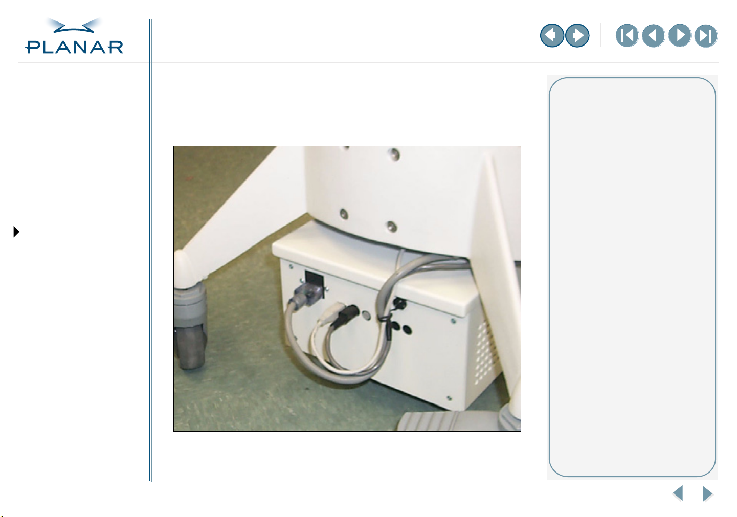
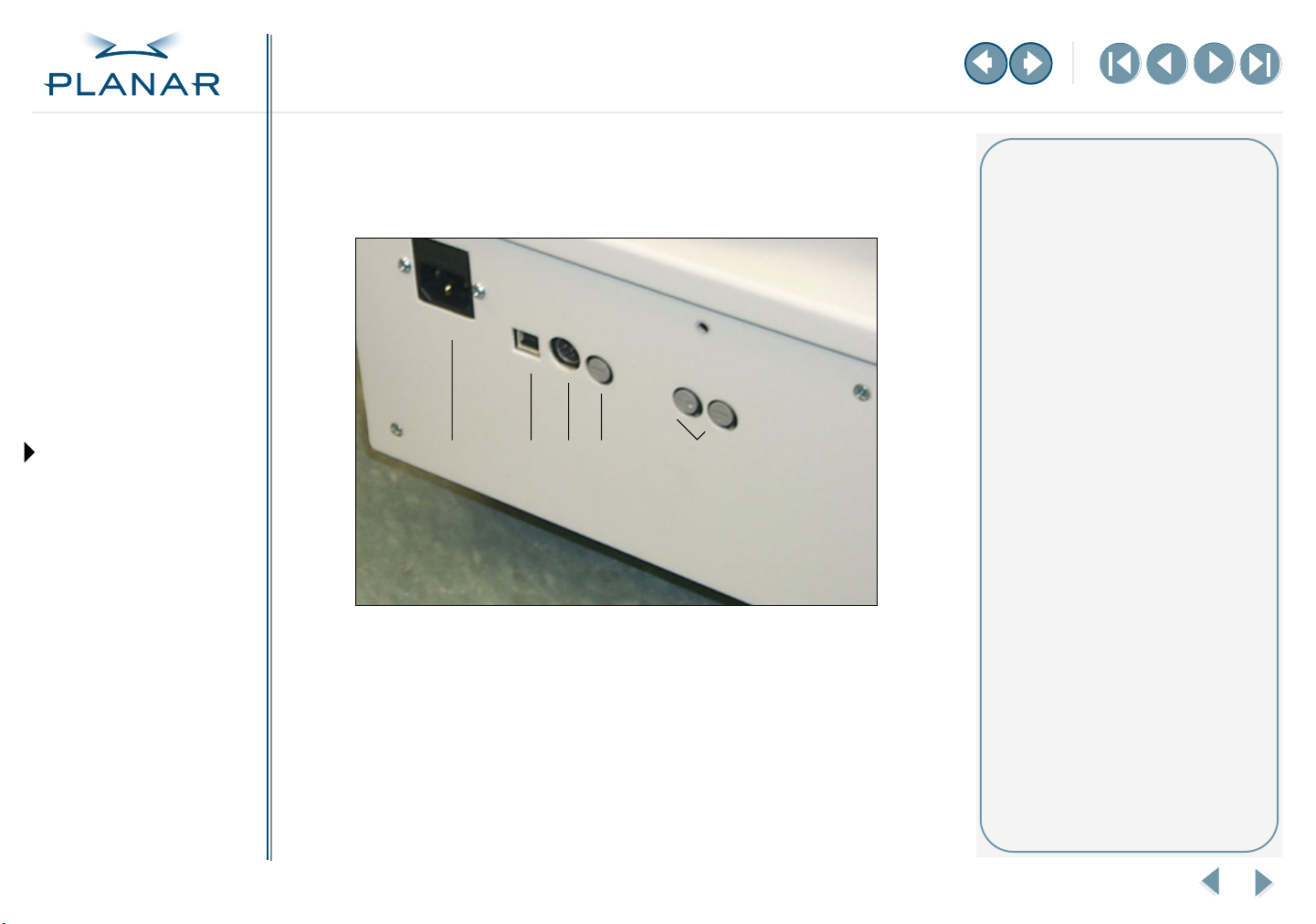
Identify the Connector Ports
All external connections to the battery system are located on the rear of the battery
enclosure. The design of the enclosure minimizes liquid ingress.
1
3
2
4
5
Legend
1 Standard IEC 120–250V AC
input power
2 A, 250 V replaceable
2 USB serial port
Communication channel
between the power supply and
its host computer
3 12V DC 6 A output power
Mini-DIN 4-pin device; requires
an external power cable
4 Output power fuse
6 A replaceable
5 Battery fuse
6 A replaceable
Troubleshooting
APPENDIXES
Battery Disposal
Specifications
Invitium Battery System BAT-24CM
3
Page 9
QUICK LINKS
Contents
Index
Regulatory Compliance
Product Information
Warranty
GETTING STARTED
About the Battery System
Locate Battery Housing
Identify Connector Ports
Install Battery Fuses
USING THE BATTERY
Charge Battery
Set Up Power Management
MAINTAINING THE BATTERY
Replace Battery
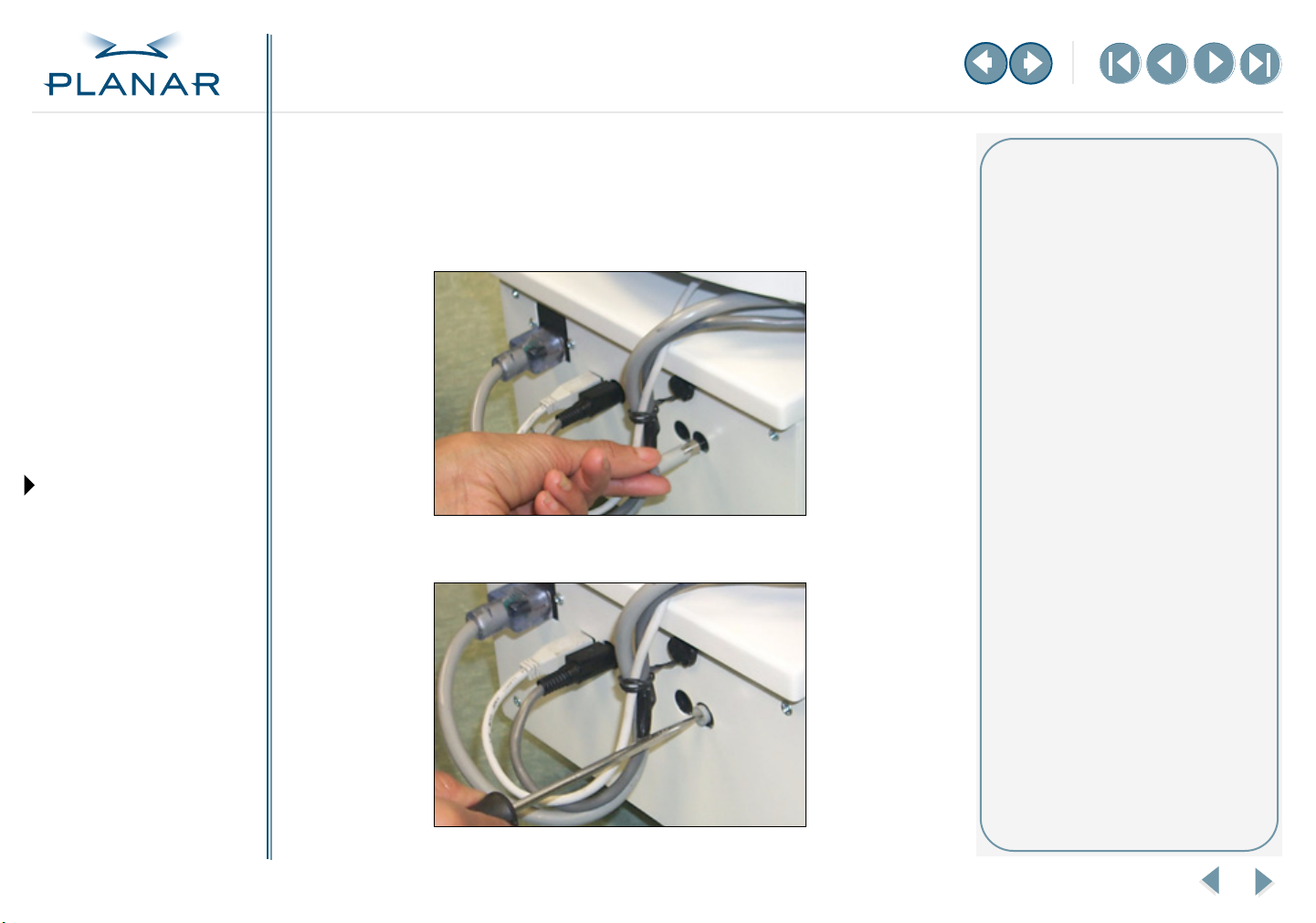
Install the Battery Fuses
You need the two battery fuses and a screwdriver for this installation.
To install a battery fuse
1
Push the fuse in until you feel the connection.
2
Use a screwdriver to secure the connection.
About the battery fuses
The Invitium battery system requires
two 6 A fuses. These are available
from any hardware store.
Securing the fuse connection
Use the screwdriver to turn the fuse
holder approximately a quarter to
the right, or until you feel it lock.
Troubleshooting
APPENDIXES
Battery Disposal
Specifications
Invitium Battery System BAT-24CM
4
Page 10

QUICK LINKS
Contents
Index
Regulatory Compliance
Charge the Battery
This section provides basic information on battery operations. See specifications on
battery charging, charging controller board, and power consumption efficiency for
more information.
Product Information
Warranty
GETTING STARTED
About the Battery System
Locate Battery Housing
Identify Connector Ports
Install Battery Fuses
USING THE BATTERY
Charge Battery
Set Up Power Management
MAINTAINING THE BATTERY
Replace Battery
Troubleshooting
APPENDIXES
Battery Disposal
Specifications
Battery charging
Plug the battery system into an AC power source for charging.
Charge time
The charging controller board is capable of independently charging the batteries
while powering the attached system. This ensures that the charge rate of the
batteries is the same whether a load is connected or not. Charge time varies
depending on the age and usage of the battery. Typically, as a battery ages, it
tends to accept less charge; that is, the charge time decreases. Consequently,
as the battery accepts less charge, the battery usage time decreases.
Charge Time Capacity of Charge
3 hours 80%
4 hours 90%
6 hours 100%
Periodically, charge the battery for 10 hours. This assures that the maximum charge
capacity of the battery is maintained. The charger enters the trickle charging cycle
after the current supplied to the batteries drops below .5 amps. Charge the batteries
for 10 hours for every eight charges to 100%.
Invitium Battery System BAT-24CM
5
Page 11

QUICK LINKS
Contents
Index
Regulatory Compliance
Product Information
Battery discharging
You discharge the battery by (1) disconnecting the battery system from the
AC power source and (2) powering the load.
When the battery has been discharged for a long period of time, it reaches a point
at which it needs to cut off power to its load. The battery system communicates to
the host computer and requests a safe shutdown or hibernation.
Warranty
GETTING STARTED
About the Battery System
Locate Battery Housing
Identify Connector Ports
Install Battery Fuses
USING THE BATTERY
Charge Battery
Set Up Power Management
MAINTAINING THE BATTERY
Replace Battery
Troubleshooting
APPENDIXES
Battery Disposal
Specifications
Thermal protection
The universal power supply is thermally protected and self-resetting. The battery
enclosure contains a cooling fan that is activated whenever the system is plugged
into an AC power source.
Depth of discharge protection
After the power to the load is cutoff, the internal circuitry goes into sleep mode to
prevent further battery discharging. The sleep mode is intended to prevent the
batteries from deep discharge.
Invitium Battery System BAT-24CM
6
Page 12

QUICK LINKS
Contents
Index
Regulatory Compliance
Product Information
Warranty
GETTING STARTED
About the Battery System
Locate Battery Housing
Identify Connector Ports
Install Battery Fuses
USING THE BATTERY
Charge Battery
Set Up Power Management
MAINTAINING THE BATTERY
Replace Battery
Set Up the Power Management System
All communications occur through the USB serial interface. These are displayed
through the Windows Power Options Properties dialog box on the host computer.
To set up power management
1
Open the Control Panel and click the Power Options tool.
Easier power management
Unlike earlier Invitium battery
systems, this system has no charge
indicator panel.
The charge level indicator is
software-driven, complying with
the Microsoft Windows HID Power
Device Specification.
You manage power consumption
using the Power Options tool in
the Windows Control Panel.
Troubleshooting
APPENDIXES
Battery Disposal
Specifications
Invitium Battery System BAT-24CM
7
Page 13

QUICK LINKS
Contents
Index
Regulatory Compliance
Product Information
2
Click the Alarms tab on the Power Options Properties dialog box.
Low battery alarm
User-selectable alarm that is audible
or silent. The alarm is triggered when
the battery charge level reaches its
low battery limit.
Warranty
GETTING STARTED
About the Battery System
Locate Battery Housing
Identify Connector Ports
Install Battery Fuses
USING THE BATTERY
Charge Battery
Set Up Power Management
MAINTAINING THE BATTERY
Replace Battery
Troubleshooting
APPENDIXES
Battery Disposal
Specifications
3
To set either the low battery alarm or critical battery alarm, or both alarms:
• Click the check box to activate alarm mode.
•Move the slider to the point at which you want the alarm to trigger.
• Click the Alarm Action button to do one or more of the following: select
the type of notification, set a computer action, run a specific program.
Critical battery alarm
User-selectable alarm that is audible
or silent. The alarm is triggered when
the battery charge level reaches its
depth of discharge limit.
Hibernation/shut down action
If a hibernation or shut down action
is enabled, the low or critical battery
alarm limit should not be greater
than 5% to ensure proper operation.
Alarm disabled
Deselect the check box to disable
the low battery or critical battery
alarm.
Invitium Battery System BAT-24CM
8
Page 14

QUICK LINKS
Contents
Index
Regulatory Compliance
Product Information
Warranty
GETTING STARTED
About the Battery System
Locate Battery Housing
Identify Connector Ports
Install Battery Fuses
4 Select the notification you want, one of the two types or both. Click OK.
Alarm action
An alarm action to hibernate or shut
down can be selected in the Power
Options Properties menu.
Alarm notification
You must select a notification for
the alarm you choose. Selecting an
alarm action or running a program
is optional.
To set an alarm action:
1 Click the check box to activate
the option.
2 Select an action from the
pull-down list.
USING THE BATTERY
Charge Battery
Set Up Power Management
MAINTAINING THE BATTERY
Replace Battery
Troubleshooting
APPENDIXES
Battery Disposal
Specifications
Invitium Battery System BAT-24CM
To run a program:
1 Click the check box to activate
the option.
2 Click the Configure program
button to enter your code.
9
Page 15

QUICK LINKS
Contents
Index
Regulatory Compliance
Product Information
Warranty
GETTING STARTED
About the Battery System
Locate Battery Housing
Identify Connector Ports
Install Battery Fuses
USING THE BATTERY
Charge Battery
Set Up Power Management
MAINTAINING THE BATTERY
Replace Battery
5 Open the Power Meter tab to check the power status of each battery.
• Click the check box to see the details on a battery.
• Click a battery icon for more information.
Troubleshooting
APPENDIXES
Battery Disposal
Specifications
Invitium Battery System BAT-24CM
10
Page 16

QUICK LINKS
Contents
Index
Regulatory Compliance
Product Information
Warranty
GETTING STARTED
About the Battery System
Locate Battery Housing
Identify Connector Ports
Install Battery Fuses
USING THE BATTERY
Charge Battery
Set Up Power Management
MAINTAINING THE BATTERY
Replace Battery
Replace the Battery
To remove the battery system from the cart
1 Loosen the two screws on the front of the cart.
2 Loosen the screw on the back, and tuck the cables to the side.
3 Unplug the power cord, USB cable, and output power cable.
4 Remove the two battery fuses.
5 Pull out the battery enclosure carefully and move it to a flat and stable work
surface. The unit is heavily weighted toward the front.
Replacement tips
The Invitium battery system weighs
25 pounds. Handle it carefully.
The unit is heavily weighted
toward the front of the cart. As
you remove it from the cart, you
feel its heaviness.
Once the unit is completely out of
the housing, move it to a flat and
stable work surface to replace the
batteries.
Do not mix old and new batteries.
Replace both batteries during the
same maintenance session.
The battery system is a self-aligning
unit. When you return it to the cart,
push it all the way in. The alignment
occurs automatically.
Troubleshooting
APPENDIXES
Battery Disposal
Specifications
Invitium Battery System BAT-24CM
11
Page 17

QUICK LINKS
Contents
Index
Regulatory Compliance
Product Information
Warranty
GETTING STARTED
About the Battery System
Locate Battery Housing
Identify Connector Ports
Install Battery Fuses
USING THE BATTERY
Charge Battery
Set Up Power Management
MAINTAINING THE BATTERY
Replace Battery
To replace the battery
1 Loosen the two screws and remove the retaining bracket.
2 Detach the four battery terminal cable connectors and move them to the side.
Replacement tips
Use only Yuasa NP 12-12 or
B&B EP 12-12 batteries.
Troubleshooting
APPENDIXES
Battery Disposal
Specifications
3 Replace both batteries at the same time. Do not mix old and new batteries.
4 Reconnect the four terminal cable connectors. Push in the connector until you
feel the connection click.
5 Reattach the retaining bracket with the two screws.
Invitium Battery System BAT-24CM
12
Page 18

QUICK LINKS
Contents
Index
Regulatory Compliance
Product Information
Warranty
GETTING STARTED
About the Battery System
Locate Battery Housing
Identify Connector Ports
Install Battery Fuses
USING THE BATTERY
Charge Battery
Set Up Power Management
MAINTAINING THE BATTERY
Replace Battery
To reinstall the battery system into the cart
1 Push the battery system all the way into the housing area.
2 Plug in the power cord, USB cable, and power output cable.
3 Reinsert the two battery fuses.
4 Reinsert the three screws, one in the back and two in the front.
Troubleshooting
APPENDIXES
Battery Disposal
Specifications
Invitium Battery System BAT-24CM
13
Page 19

QUICK LINKS
Contents
Troubleshooting
Index
Regulatory Compliance
Product Information
Warranty
GETTING STARTED
About the Battery System
Locate Battery Housing
Identify Connector Ports
Install Battery Fuses
USING THE BATTERY
Charge Battery
Set Up Power Management
MAINTAINING THE BATTERY
Replace Battery
Troubleshooting
APPENDIXES
Battery Disposal
Specifications
Problem Possible Cause Possible Solution
The battery system not functioning,
no output power, does not charge
when connected to AC power.
No power supplied to Invitium system. Output power cord not connected properly. Make sure that output power cord is
System run time is too short. Battery not completely charged. Connect AC power and let battery charge
AC power is not connected. Make sure power cord is connected properly
Input fuse needs to be replaced. Replace fuse in input connector. Replace
with UL recognized fuse 2 A, 250 VAC,
fast acting, size 5 mm x 20 mm.
Over-temperature protection is activated. Contact Planar.
connected correctly. When the power LED
on the right side of the Invitium workstation
is green, it indicates normal operating mode.
Power switch is off. Turn on the power switch, located on
the right side of the Invitium workstation.
Output fuse needs to be replaced. Replace the output power fuse located next
to output power connector. Replace with
UL recognized fuse 6 A, 125 VDC, fast acting,
size.25 in. x 1.25 in.
Batteries not connected correctly. Check battery connections.
completely. Charge status is conveyed
through the Power Meter tab on the
Power Options Properties dialog box.
Battery capacity is low. Replace battery.
Invitium Battery System BAT-24CM
14
Page 20

QUICK LINKS
Contents
Index
Regulatory Compliance
Product Information
Warranty
GETTING STARTED
About the Battery System
Locate Battery Housing
Identify Connector Ports
Install Battery Fuses
USING THE BATTERY
Charge Battery
Set Up Power Management
MAINTAINING THE BATTERY
Replace Battery
Battery Disposal
Industrial batteries contain lead and sulfuric acid, which are both considered
“hazardous substances.” If batteries are improperly disposed of, for example, thrown
in the trash or illegally dumped, these substances can eventually leak out and
contaminate the surrounding soil and groundwater supply.
It is a federal law to properly dispose of lead-acid batteries once they can no longer be
used. Once a battery is purchased, full liability and responsibility lies on the owner to
dispose of the battery.
The law says that responsibility is still on the owner if the battery is disposed of
improperly by dumping in a landfill, or shipping to a scrap dealer who does not
handle it properly and in which environmental damage occurs.
It is illegal to dispose of batteries in any way other than ”thermal recovery” or
recycling of the hazardous substances in batteries according to the Environmental
Protection Agency (EPA).
The Department of Transportation (DOT) has strict guidelines for the shipping of
hazardous materials, which result in large fines if they are not followed.
Check with your local ordinances for proper disposal procedures.
Troubleshooting
APPENDIXES
Battery Disposal
Specifications
Invitium Battery System BAT-24CM
15
Page 21

QUICK LINKS
Contents
Battery System Specification
Index
Regulatory Compliance
Product Information
Warranty
GETTING STARTED
About the Battery System
Locate Battery Housing
Identify Connector Ports
Install Battery Fuses
USING THE BATTERY
Charge Battery
Set Up Power Management
MAINTAINING THE BATTERY
Replace Battery
Troubleshooting
APPENDIXES
Battery Disposal
Specifications
Technical summary
The battery system is a self-contained regulated power supply, battery, and charger unit,
packaged in a sheet metal enclosure.
Features
• Universal AC input
• Regulated 12V DC output
• Fast charging
Electrical specifications
Input Input voltage 85 to 265 VAC
Input frequency 47 to 63 Hz
Inrush current limiting <50A peak
Input protection 2A, 250V replaceable fuse
Power factor 0.95 (150 W, 230 VAC)
Output Output voltage 12 VDC ±5%
Output current 6.0 A maximum
Output power 36 watts nominal; 72 watts maximum
Overload recovery Automatic upon fault removal
Overload protection 6A replaceable fuse
Operating time 4 hours at nominal output power
Output efficiency >88%
Invitium Battery System BAT-24CM
• Intelligent communications (USB host)
• Cooling fan
• Externally accessible fuses
–MORE–
16
Page 22

QUICK LINKS
Contents
Index
Regulatory Compliance
Product Information
Warranty
Battery requirements
Battery type Sealed lead acid; quantity – 2
Yuasa NP12-12 or B and B EP12-12
Capacity 12 Ah each
Output voltage range 12 V nominal 9.5 to 14.4 V
Cycle life approx. 250 full charge cycles
GETTING STARTED
About the Battery System
Locate Battery Housing
Identify Connector Ports
Install Battery Fuses
USING THE BATTERY
Charge Battery
Set Up Power Management
MAINTAINING THE BATTERY
Replace Battery
Troubleshooting
APPENDIXES
Battery Disposal
Specifications
Connectors/cables
Input power connector Standard IEC power connector
USB port connector Standard USB cable (A male to B male)
Output power connector Mini-DIN 4-pin device
Charging
Charge time (new battery) 3 hours to 80%
4 hours to 90%
6 hours to 100%
Invitium Battery System BAT-24CM
–MORE–
17
Page 23

QUICK LINKS
Contents
Index
Regulatory Compliance
Product Information
Warranty
GETTING STARTED
About the Battery System
Locate Battery Housing
Identify Connector Ports
Four modes of the battery system
Charging mode The battery system is plugged into an AC power source. During charging
mode, the attached load to the battery system is operational. The
batteries charge. The cooling fan runs only when the unit is plugged
into an AC power source.
Running mode The batteries have some level of charge and the battery system is not
plugged into an AC power source. During running mode, the attached
load to the battery system is operational. The batteries discharge. The
cooling fan is off. The load to the battery system is active.
Stand-by mode The batteries have some level of charge, the battery system is not
plugged into an AC power source, and the load is either disconnected
or off. The cooling fan is off. The load is powered when the system is
either turned on or reconnected.
Install Battery Fuses
USING THE BATTERY
Charge Battery
Set Up Power Management
MAINTAINING THE BATTERY
Replace Battery
Troubleshooting
APPENDIXES
Battery Disposal
Specifications
Off mode The batteries have no charge and the battery system is not plugged
into an AC power source. During off mode, the attached load to the
battery system is not operational, whether connected or turned on.
The controller board is in sleep mode. The cooling fan is off. Plug the
battery system into an AC power source to leave off mode.
Invitium Battery System BAT-24CM
–MORE–
18
Page 24

QUICK LINKS
Contents
Index
Regulatory Compliance
Product Information
Warranty
GETTING STARTED
About the Battery System
Locate Battery Housing
Identify Connector Ports
Power consumption efficiency
The charging controller board has four levels of power consumption: charging, running,
stand-by, and off.
Charging mode The batteries are charged using a constant current/constant voltage
algorithm. A constant current of 3.0 amps max is applied to each battery
until the voltage on the battery reaches 14.4 V. The current exponentially
decreases to maintain 14.4 V on the battery. The cooling fan is on during
this cycle. The +12VDC regulator circuitry is powered by the power
supply, and the communication system reports the charge status of
the batteries to the host.
Running mode The board consumes power at a rate proportional to the power
consumed by the load during its running mode. The board proves to
be 88% efficient when connected to a 4.5 amp load.
Install Battery Fuses
USING THE BATTERY
Charge Battery
Set Up Power Management
MAINTAINING THE BATTERY
Replace Battery
Troubleshooting
APPENDIXES
Battery Disposal
Specifications
Stand-by mode The board consumes about 8.5 mA of current when in stand-by mode.
A fully charged and new battery lasts about 3 months in the battery
system before it needs to be replaced.
Off mode The board consumes about 350 µA of current when in the stand-by
mode. A fully charged and new battery lasts about 3 months in the
battery system before it needs to be replaced. The battery continues
to drain at a rate of 350 µA. Batteries that are not connected to the
controller board have a shelf life of 1 month 97%, 3 months 91%,
6 months 85%, at 68° F.
Invitium Battery System BAT-24CM
19
Page 25

QUICK LINKS
Contents
Index
Regulatory Compliance
Product Information
Warranty
GETTING STARTED
About the Battery System
Locate Battery Housing
Identify Connector Ports
Install Battery Fuses
USING THE BATTERY
Charge Battery
Set Up Power Management
MAINTAINING THE BATTERY
Replace Battery
Troubleshooting
APPENDIXES
Battery Disposal
Specifications
Index
A
alarm
critical battery 8
disabled 8
low battery 8
setting 8, 9
B
battery
about system 1
charging 5
connector ports 3
discharge protection 6
discharging 6
disposal 15
fuses 3, 4
housing 2
input power 3
maintaining system 11
models 1
output power 3
power consumption 19
reinstalling 13
removing 11
replacing 11, 12
specifications 16
thermal protection 6
USB serial port 3
C
cables/connectors 2, 17
charge time 5
charging battery 5
charging controller board 17, 18
cleaning guidelines v
compliance 24
components, identifying 3
controller board, charging 17, 18
customer support 22
D
discharge protection 6
discharging battery 6
disposing of battery 15
F
fuses 3, 4
G
guidelines
cleaning v
safety iv
I
identifying components 3
IEC connector 3
information
product iv
regulatory 24
installing fuses 4
M
maintaining battery system 11
N
notification, alarm 9
O
output power 3
fuse 3
port 3
overview of battery system 1
P
ports, connector 3
power
checking status 10
connector 3
consumption 19
management 7
Power Meter tab 10
Power Options tool 7
product information iv
protection
depth of discharge 6
thermal 6
R
regulatory information 24
reinstalling battery 13
removing battery 11
replacing battery 11, 12
S
safety guidelines iv
service v
setting alarm 8
specification, battery 16
symbol explanations 27
T
thermal protection 6
troubleshooting 14
U
USB serial port 3
W
warranty 21
Windows HID power device 7
workstation, cleaning v
Invitium Battery System BAT-24CM
20
Page 26

QUICK LINKS
Contents
Overview of Standard Warranty
Index
Regulatory Compliance
Product Information
Warranty
GETTING STARTED
About the Battery System
Locate Battery Housing
Identify Connector Ports
Install Battery Fuses
USING THE BATTERY
Charge Battery
Set Up Power Management
MAINTAINING THE BATTERY
Replace Battery
Troubleshooting
APPENDIXES
Battery Disposal
Summary
• Standard 1-year “repair and return” warranty on all Invitium Medical Workstations
• Typical repair turnaround time of 10 business days
• Repair facilities and technical support in the United States and in Europe
Standard Warranty Return Procedure
As a Planar Standard Warranty customer, you must follow the procedure below if you
have a non-functioning Invitium Medical Workstation. Planar customer service staff will
attempt to correct any minor issues that may be causing the problem. Once Planar has
determined that you have a non-functioning product, Planar will arrange for return and
repair of the non-functioning product.
1 Contact Planar via the web at http://www.planar.com/support. In North America, call
(866) PLANAR1 (866.752.6271). In Europe, call +358 9 420 01 or send your info by fax
to +358 9 420 0200. You must have the model number, serial number, and proof-ofpurchase available.
2 Planar customer service staff will attempt to correct any minor issues that may be
causing the problem. If we are unable to correct the problem to your satisfaction,
we will issue a Return Material Authorization (RMA).
3 You must return the product, as specified, to Planar Systems. Do not return the
battery cell or cart to planar Systems unless directed by Planar customer service.
4 Planar will validate the defect, repair the unit, and return the unit to you. The typical
turnaround time is 10 business days.
At its sole discretion, Planar may charge you the customer for returned units deemed
functional or for returned units with only customer-caused damage. It is the responsibility of
the customer to properly package the hardware, include all appropriate materials, and return
it to the location specified by Planar customer service.
Specifications
Invitium Battery System BAT-24CM
–MORE–
21
Page 27

QUICK LINKS
Contents
Index
Regulatory Compliance
Product Information
Warranty
GETTING STARTED
About the Battery System
Locate Battery Housing
Identify Connector Ports
Install Battery Fuses
USING THE BATTERY
Charge Battery
Summary Limitations and Exclusions of Invitium Medical Workstations
1 Invitium warranty is valid only for the first consumer purchaser (non-transferable).
2 Invitium warranty does not cover the battery cell(s), mouse, or keyboard.
3 The customer must provide original proofs of purchase for the Invitium hardware.
4 Warranty is void on any product with a defaced, modified, or removed serial number.
5 Warranty is void on any product with damage, deterioration, or malfunction resulting
from the following:
a) Accident, misuse, neglect, fire, water, lightning, or other acts of nature, unauthorized
product modification, or failure to follow instructions supplied with the product.
b) Repair or attempted repair by anyone not authorized by Planar.
c) Any damage of the product due to shipment.
d) Removal or installation of the product.
e) Causes external to the product, such as electric power fluctuations or failure.
f) Use of supplies or parts not meeting Planar specifications.
g) Normal wear and tear, including backlights dimming over time.
h) Any other cause which does not relate to a product defect.
6 Warranty excludes removal, installation, and setup service charges.
Customer support
In North America, call 1 (866) PLANAR1
between 8
Monday through Friday, or send
a description of your technical
issues and e-mail address to
medicalsupport@planar.com.
In Europe, call +358 9 420 01 between
8
A.M. and 4 P.M. Finnish time (Eastern
European time), Monday through
Friday, or send a description of your
technical issues and e-mail address to
medicalsupport@planar.com.
A.M. and 5 P.M. Pacific time,
Set Up Power Management
MAINTAINING THE BATTERY
Replace Battery
Troubleshooting
APPENDIXES
Battery Disposal
Specifications
Limitation of Implied Warranties
THERE ARE NO WARRANTIES, EXPRESS OR IMPLIED, WHICH EXTEND BEYOND THE
DESCRIPTION CONTAINED HEREIN INCLUDING THE IMPLIED WARRANTY OF
MERCHANTABILITY AND FITNESS FOR A PARTICULAR PURPOSE.
–MORE–
Invitium Battery System BAT-24CM
22
Page 28

QUICK LINKS
Contents
Index
Regulatory Compliance
Product Information
Warranty
GETTING STARTED
About the Battery System
Exclusion of Damages
THE LIABILITY OF PLANAR IS LIMITED TO THE COST OF REPAIR OR REPLACEMENT OF
THE PRODUCT. PLANAR SHALL NOT BE LIABLE FOR THE FOLLOWING:
1 DAMAGE TO OTHER PROPERTY CAUSED BY ANY DEFECTS IN THE PRODUCT,
DAMAGES BASED UPON INCONVENIENCE, LOSS OF USE OF THE PRODUCT, LOSS
OF TIME, LOSS OF PROFITS, LOSS OF BUSINESS OPPORTUNITY, LOSS OF GOODWILL,
INTERFERENCE WITH BUSINESS RELATIONSHIPS, OR OTHER COMMERCIAL LOSS,
EVEN IF ADVISED OF THEIR POSSIBILITY OF SUCH DAMAGES.
2 ANY OTHER DAMAGES, WHETHER INCIDENTAL, INDIRECT, CONSEQUENTIAL, OR
OTHERWISE.
3 ANY CLAIM AGAINST THE CUSTOMER BY ANY OTHER PARTY.
Locate Battery Housing
Identify Connector Ports
Install Battery Fuses
USING THE BATTERY
Charge Battery
Set Up Power Management
MAINTAINING THE BATTERY
Replace Battery
Troubleshooting
APPENDIXES
Battery Disposal
Specifications
Effect of Local Law
This warranty gives you specific legal rights, and you may have other rights, which vary from
locality to locality. Some localities do not allow limitations on implied warranties and/or do
not allow the exclusion of incidental or consequential damages, so the above limitations and
exclusions may not apply to you.
Invitium Battery System BAT-24CM
23
Page 29

QUICK LINKS
Contents
Index
Regulatory Compliance
Product Information
Warranty
GETTING STARTED
About the Battery System
Locate Battery Housing
Identify Connector Ports
Install Battery Fuses
USING THE BATTERY
Charge Battery
Set Up Power Management
MAINTAINING THE BATTERY
Replace Battery
Troubleshooting
Regulatory Information
U.S. Federal Communications Compliance Statement
The Planar Invitium Battery (model BAT-24CM) have has been tested and found to comply
within the limits of a Class B digital device pursuant to Part 15 of the FCC Rules. These limits are
designed to provide reasonable protection against interference in a residential installation.
This equipment generates, uses, and can radiate radio frequency energy and, if not
installed and used in accordance with the instruction, may cause harmful interference to
radio communications. However, there is no guarantee that interference will not occur in
a particular installation.
If this equipment does cause harmful interference to radio or television reception (which can
be determined by turning the equipment on and off), the user is encouraged to try to correct
the interference by using one or more of the following measures:
• Reorient or relocate the receiving antenna.
• Increase the separation between the equipment and the receiver.
• Connect the equipment into an outlet on a circuit different from that
to which the receiver is connected.
• Consult the dealer or an experienced radio/TV technical for help.
Canadian DOC Notice
This digital apparatus does not exceed the Class B limits for radio noise emissions from digital
apparatus as set out in the Radio Interference Regulation of the Canadian Department of
Communications.
“Le present appareil numerique n’emet pas de bruits radioelecinques depassant les limires
applicables aux appareils numeriques de la class B prescrites dans le Reglement sure le
brouiliage radioelectrique edicte par le minstere des Communications du Canada.”
Caution
To comply with the limits for an
FCC Class B computing device,
always use the cords supplied with
the unit. The FCC warns that changes
or modification of the unit not
expressly approved by the party
responsible for compliance could
void the user’s authority to operate
the equipment.
APPENDIXES
Battery Disposal
Specifications
Invitium Battery System BAT-24CM
–MORE–
24
Page 30

QUICK LINKS
Contents
Index
Regulatory Compliance
Product Information
Warranty
GETTING STARTED
About the Battery System
Locate Battery Housing
Identify Connector Ports
Install Battery Fuses
USING THE BATTERY
Charge Battery
Set Up Power Management
MAINTAINING THE BATTERY
Replace Battery
Troubleshooting
APPENDIXES
Battery Disposal
Regulatory Compliance
This system has been tested and found to comply with IEC/CSA 601-1, UL 60601-1 and
CAN/CSA C22.2 No. 601.1 medical standards by CSA.
Because many medical offices are located in residential areas, the Invitium battery system, in
addition to meeting medical requirements, has also been tested and found to comply with the
limits for Federal Communications Commission (FCC) Class B computing devices in a typically
configured system. It is the responsibility of the system integrator or configurer to test and
ensure that the entire system complies with applicable electromagnetic compatibility (EMC)
laws. Planar Systems, Inc. has made great efforts to support the medical device industry, in
particular medical device manufacturers and medical device system integrators. We offer
state-of-the-art systems that are compliant with worldwide accepted medical device safety
standards, and for the European market, EC-marked displays based on compliance with
counsel directive 93/42/EEC — commonly referred to as the Medical Device Directive (MDD).
The following summarizes our qualification of these displays as it relates to compliance with
the MDD.
The European MDD requires that the intended use of the device be defined. The intended use
of the Invitium workstation is “to display alphanumeric, graphic, and image data as inputted
from any type of medical device.” This system does not provide a measurement function in
any way, and it is the device and systems manufacturers responsibility to verify its function
in the integrated device or system. The workstation was classified as required by the MDD
according to Annex IX of the directive and the medical device (MEDDEV) guidance available
at the time of classification.
Because the workstation uses electrical energy and has no direct patient connections and —
by itself — no medical utility, the workstation is classified according to Rule 12 as an MDD
Class I device-component or accessory.
The MDD states that manufacturers of Class I medical devices or accessories shall satisfy the
requirements in regard to design and manufacturing controls; in other words, the applicable
assessment route to be used for CD-marking under the MDD, and it shall carry the CD-mark
according to Annex XII for the directive, with no notified body annotation.
Specifications
Invitium Battery System BAT-24CM
–MORE–
25
Page 31

QUICK LINKS
Contents
Index
Regulatory Compliance
Product Information
Warranty
GETTING STARTED
About the Battery System
Locate Battery Housing
Identify Connector Ports
Install Battery Fuses
USING THE BATTERY
Charge Battery
Set Up Power Management
MAINTAINING THE BATTERY
Replace Battery
Troubleshooting
The applicable safety standards for an MDD Class I device are IEC/EN60601-1: 1990 along with
Amendments 1 and 2. To help the medical device designer evaluate the suitability of these
workstations, Planar has also conducted EMC testing to IEC 60601-1-2 as it can be applied.
The display with its power supply alone does not represent a functional medical device.
Hence, Planar configured a minimal operating system to exercise the display. The resulting
data is made available to interested parties.
The data is informative data, not certification data. Certification data must be obtained by the
device or system integrator according to Article 12 of the MDD titled “Particular procedure for
systems and procedure packs.” Paragraph 2 clearly outlines the device or system integrator’s
responsibility in this matter.
In summary, Planar Systems, Inc. is CE-marking these workstations under the Medical Device
Directive, which establishes compliance to the basic medical safety standards. However, EMC
compliance can only be accomplished in the configured medical device or system and is the
responsibility of the device or system manufacturer. Planar has the necessary documentation
such as IEC 60601-1 notified body and other third-party test reports and certifications, a risk/
hazard analysis, and essential requirements checklist, and Planar’s International
Electrotechnical Commission (IEC) declaration of conformity.
Planar Systems, Inc., located in Beaverton, Oregon, USA, is the manufacturer of these
workstations in the meaning of the directive. As required by the MDD in Article 14,
Planar Systems, Inc. not residing in the European Economic Area (EEA) has a European
Representative, Planar Systems, Inc. – Espoo, Finland.
In the opinion of Planar Systems, Inc. registration required to put its device into commerce
is the responsibility of the medical device/system manufacturer, and Planar supports this
requirement by providing a European Commission (EC) declaration of conformity. If Planar
supplies a workstation to an end user, rather than a device manufacturer, it is the end user’s
responsibility to ensure continued compliance with the MDD of the system in which the
workstation is integrated. For vigilance reporting as required under Article 10 of the MDD,
Planar Systems, Inc. will provide any information requested by competent authority to
support any reported incident investigation by such an authority.
APPENDIXES
Battery Disposal
Specifications
Invitium Battery System BAT-24CM
–MORE–
26
Page 32

QUICK LINKS
Contents
Index
Regulatory Compliance
Product Information
Warranty
Symbol explanations
Following are explanations of the symbols found on the Invitium battery, model BAT-24CM).
E226863
Product has been tested and certified with respect to electric shock,
fire, mechanical and other specified hazards only in accordance with
US 2601-1 and CAN/CSA C22.2 No. 601.1 and IEC 60601-1 for medical
UL 60601-1
CAN/CSA C22.2 NO.601.1
CLASS 8750
equipment. If this mark appears with the indicators “C” and “US”, the
product is certified for Canadian and U.S. markets, meeting the
applicable Canadian and U.S. standards.
GETTING STARTED
About the Battery System
Locate Battery Housing
Identify Connector Ports
Install Battery Fuses
USING THE BATTERY
Charge Battery
Set Up Power Management
MAINTAINING THE BATTERY
Replace Battery
Troubleshooting
APPENDIXES
Battery Disposal
Specifications
Proof of conformity to applicable European Economic Community
Council directives and two harmonized standards published in the
official journal of the European Communities.
Product has been tested to comply with FCC Class B standards.
Consult accompanying documents.
Indoor use only.
IPX1 Drip-Proof rating per IEC/EN60529
DC (direct current) voltage
~
AC (alternating current) voltage
Fuse
Invitium Battery System BAT-24CM
27
 Loading...