

Page 1

WaveSwitch 100
Ethernet Switch
User Manual
Page 2

© 1994, 1995 Plaintree Systems, Inc.
All rights reserved
Printed in Canada
Information in this document is subject to change without notice, and does not represent a
commitment on the part of Plaintree Systems, Inc. The software described in this document is
furnished under a license agreement and may be used or copied only under the terms of the
agreement. It is against the law to copy the software except as permitted by the license agreement .
Document part number/version: 12195
Software version: 3.23
Date of issue: December 1995
12195WaveSwitc h 100 Ethe rn et Swit chUser Manual
WaveSwitch, WaveBus, WaveBus MSL, and Plaintree are registered trademarks of Plaintree Systems, Inc. Novell and
NetWare are registered trademarks of Novell, Inc. Ethernet is a registered trademark of Xerox, Inc. ST is a registered
trademark of American Telephone and Telegraph Company. MS-DOS is a registered trademark of Microsoft Corporation.
Windows is a trademark of Microsoft Corporation. SC is a trademark of NTT Advanced Technology Corporation. AMP is a
trademark of AMP Incorporated. PROCOMM PLUS for DOS and PROCOMM PLUS for Windows are trademarks of
DATASTORM TECHNOLOGIES, INC. VT100 is a trademark of Digital Equipment Corporation.
ii WaveSwitch 100 Ethernet Switch User Manual 12195
Page 3

Technical support and product information
Techni cal sup port
Product support staff are available to answer technical questions between
8:00 a.m. and 8:00 p.m. EST, Monday to Friday.
Telephone: 1 800 831 1095 (toll free)
1 613 831 8883
Fax: 1 613 831 6120
You can also contact product support staff using electronic mail on the
Internet by sending a message to:
Product information
You can download software updates, test tools, product documentation, and
other informati on from Plai ntree’ s Bulletin Board System or FTP site.
Bulletin board system (BBS)
You can contact the Plaintree Systems BBS at (613) 831-8312. The BBS
settings are 8 data bits, 1 stop bit, and no parity. The preferred file transfer
protocol is ZMODEM. The BBS transfers data up to 14,400 baud.
The latest WaveSwitch 100 user documentation is available from the BBS.
Most documents are contained in .EXE compressed self-extracting files.
To download an item, select Main Menu/Files Menu/Download a File and
choose a file. After downloading, enter filename.E XE on the command line
to uncompress the contents into a PostScript file.
Plaintree Syste ms FTP sit e
You can contact the Plaintree FTP site at ftp.plaintree. com to download
files that contain software upgrades and product documentation.
Plaintree Syste ms Web site
For up-to-date inform ation about Plaintr ee products, see the Plaintre e
Systems Home Page on the World Wide Web at the following URL:
http://www.plaintree.com/plaintree
Plaintree Syste ms sales telephone numbers
Call for information about Plaintree Sy stems products.
In the United States: 1 800 370 2724 (toll free)
In Canada: 1 800 563 1178 (toll free)
In the U.K. and Europe: + 44 13 44 38 20 96
In the rest of the world: + 1 617 290 5800
+ 1 617 290 0963 (Fax)
WaveSwitch 100 Ethernet Switch User Manual iii
Page 4

Plaintree Systems product warranty
Plaintree Systems products are guaranteed to be free from manufacturing
and material defects for one (1) year from the date of original purchase by
the end user.
Plaintree Systems will, at its option, repair or replace any defective part
without charge for the part within one year from the date of original
purchase. Plaintree Systems will also bear the entire labor expense for any
warranty repair when the defective product is returned to the factory or to a
Plaintree Systems-appointed repair facility.
Shipping expenses to the factory are the responsibility of the purchaser.
To qualify for warranty service, the purchaser must notify Plaintree Systems
of any alleged defect within the one-year warranty period.
All replacements are warranted for the remainder of the original warranty
period only.
This warranty does not cover damage to the product caused by
• modification, alteration, physical abuse or misuse
• repair or service to the product by anyone other than Plaintree
Systems or a Plaintree Systems-appointed technician
• operation in a manner contrary to the instructions that accompany
the product
• freight damage
• damage caused by circumstances beyond the control of Plaintree
Systems, such as lightning or fluctuation of electrical power.
Plaintree Systems warrants that the software will perform substantially in
accordance with the documentation that accompanies the product, and is
provided “as is,” without warranty of any kind, expre ssed or implied.
Plaintree Systems sole responsibility, and the purchaser’s only remedy to
any defect in workmanship, will be to replace the defective medium
(diskette or ROM).
Under no circumstances will Plaintree Systems be held liable, in any way, to
the purchaser for damages, including loss of business profits, lost savings,
business interruption, loss of business information, or other incidental or
consequential damages arising out of the use of, or inability to use, the
product.
iv WaveSwitch 100 Ethernet Switch User Manual 12195
Page 5

Software license agreement (USA and Canada)
This agreement is a legal contract between you, the end-user, and Plaintree
Systems Inc. (“Plaintree”). Opening the sealed diskette package indicates
your acceptance of this agreement. This agreement shall also be binding on
any subsequent authorized licensee. If you do not wish to agree to the terms
of this agreement, return the package, with the seal unbroken, and the other
items which are part of this product within two weeks of receipt to Plaintree
Systems and you will receive a full refund.
Contents
The enclosed sealed package contains a Plaintree software product
(the “Software”) consisting of Plaintree trade secrets and intellectual
property (the “Program”) residing on disks (the “Medium”) to be used with
related user materials (the “Related Documentation”).
Restricted use
Title and ownership of the Program and any related trademark, trade secrets,
or copyright in the Software are and shall remain the exclusive property of
Plaintree. Upon payment for use of the Software on two (2) stand-alone
computers this Agreement entitles you to:
• use the Program on no more than two designated central processing
units (CPUs) at a time, even if more than one kind of medium is
contained in the package
• copy the Program into any machine-readable or printed for m only
for back-up purposes in support of the use of the Program on the
designated CPUs
• merge the Program with another progr am for use on the designated
CPU
Except with the express written consent of Plaintree, you are specifically
prohibited from:
• copying the Program or Related Documentation
• modifying or decompiling the Program
• transferring the Progr am or this License to any other party
• using the Program in any country other than the country in which
the Program was acquired from an authorized Plaintree
representative
• accessing the Software from a local area network workstation for
which you have not purchased and dedicated an additional copy of
the Related Documentation
WaveSwitch 100 Ethernet Switch User Manual v
Page 6

Term
This license is effective from the opening of the sealed package until
terminated. This license shall terminate automatically should you fail to
comply with any of these terms and conditions. Upon termination, the
Related Documentation and all copies of the Program must be destroyed.
Warranty
Plaintree warrant s that the Medium on which the Program is furnished will
be free of defects in materials and workmanship under normal use for a
period of thirty (30) days from the date of delivery to you.
Plaintree will replace any Softwar e that fails to deliver this limited warr anty.
If Plaintree is unable to deliver a replacement Medium that is free of defects
in materials or workmanship, you can terminate this agreement by returning
the Software.
The Program contained on the Medium is provided without warranty of any
kind, either expre ss or implied, including, but not limit ed to the implied
warranties of merchantability or fitness for a particular purpose. You are
responsible for the entire risk with respect to the quality and performance of
the Program.
Plaintree does not warranty that the function s contained in the Program will
meet your requirements or that the operations of the Program will be
uninterrupted or error free.
The exclusion of implied warrantie s is not permitted in some jurisdictions.
Consequently this exclusion may not apply to you.
Limitation of liability
In no event will Plaintree be liable to you for damages, including loss of
profits, loss of data or other incidental or consequential damages, arising out
of the use, or inability to use the Program, even where Plaintree ha s been
advised of the possibility of such damages. The limitation or exclusion of
liability for incidental or consequential damages is not permitted in some
jurisdiction s and this exclusion may therefore not apply to you.
Updates
All updates must be ordered separately from Plaintree and when delivered
become subject to the provisions of this agreement.
U.S. Government restricted rights
Use, duplication or disclosure by the U.S. Government is subject to
restrictions as set forth in subdivision (b)(3)(i i) of the Rights in Technical
Data and Computer Software clause at 52.227-7013.
vi WaveSwitch 100 Ethernet Switch User Manual 12195
Page 7

General
Except as expressly provided for in this Agreement, you may not
sublicense, assign or transfer this Agreement or any rights granted
hereunder. This Agreement will be governed by the laws of the province of
Ontario and Canada. You acknowledge having read this Agreement,
understanding it and agreeing to be bound by its terms and conditions. It is
understood that this Agreement is the complete and exclusive Agreement
between you and Plaintree (including its dealers, distributors, agents, and
employees) which supersedes any proposal or prior agreement, oral or
written, and any other communications relating to the subject matter of the
Agreement.
Should you have any questions regarding this Agreement of the Software,
please contact in writing,
Plaintree Systems Inc.
59 Iber Road
Stittsville,Ont ario
Canada K2S 1E7
WaveSwitch 100 Ethernet Switch User Manual vii
Page 8

Product compliance statements
Federal Communications Commission Notice
This equipment has been tested and found to comply with the limits for a
Class A digital device, pursuant to Part 15 of the FCC Rules. These limits
are designed to provide reasonable protection against harmful interference
when the equipment is operated in a commercial environment. This
equipment generates, uses, and can radiate radio frequency energy and, if
not installed and used in accordance with the instruction manual, may cause
harmful interf erence to radio communi cations. Operati on of this equipment
in a residential area is likely to cause harmful interference, in which case
you must correct the interference at your own expense.
Canadian Emissions Requirements (ICES-003 Issue 2)
This Class A digital apparatus meets all requirements of the Canadian
Interference-Causing Equipment Regulations.
Cet appareil numérique de la Classe A respecte toute les exigences du
Règlement sur le matériel brouilleur du Canada.
CE Mark Conformance
The WaveSwitch 100 Ethernet Switch conforms to
• EC Directive 89/336/EEC using EN55022 (1987) and
EN50082-1 (1992), according to test standards
– EN55022 (1987) [“A” Limits]
– IEC801-2 (1991) [8KV Air, Criter ia B]
– IEC801-3 (1984) [3V/m from 27Mhz to 1000Mhz, Criteri a A]
– IEC801-4 (1988) [Power Leads 1kV, Signal Leads .5kV
Criteria B]
• EN60950: 1992 Safety of Information Technology Equipm ent,
including Electrical Business Equipment
viii WaveSwitch 100 Ethernet Switch User Manual 12195
Page 9

RMA shipping instructions
If you want to return a Plaintree product, do the following:
1. Call Plaintree Systems Technical Support department (page iii) to
report the problem. Technical Support staff will try to help you fix
the problem.
Be prepared to supply the following information when you call:
– description of the problem
– description of the steps you have taken to try to correct the
problem
– status of the front-panel indicator lamps
– model number of the unit
– serial number of the unit
– software version in use
– configuration of the unit
– version of the network management system in use
– configuration of your network
If the problem cannot be fixed at your site, Technical Support staff
will supply you with a Return Material Authorization (RMA)
number.
2. Complete the Return Form supplied by Plaintree Systems
Technical Support staff.
3. Pack the item, along with the completed form, in its original
shipping box and write the RMA number on the outside of the box.
Note: If you do not have the original box, use a carton with adequate
packaging to prevent damage during shipping.
4. Ship the item to:
Plaintree Systems
59 Iber Road
Stittsvil le, ON
Canada K2S 1E7
IMPORTANT—I tems return ed for repair without an RMA numbe r will not be
accepted and will be returned to the send e r at the sende r’s expen se.
WaveSwitch 100 Ethernet Switch User Manual ix
Page 10

Using this manual
This manual contains information about how to install, connect, monitor,
and manage the WaveSwitch 100 Ethernet Switch. For information about
how to use the WaveSwitch 100 to satisfy LAN requirements and optimize
network performance, see the WaveSwitch 100 Ethernet Switch
Configuration Guide.
You can find additional information about network configur ation,
network protocols, and network engineering standard s in the books listed in
“Other publication s” on page xi.
Nota tio n conventi on s
Courier type face is used in procedures and descriptive text to show how
you should type management information, or to show what the local console
displays to you.
Information that you must enter exactly as it is shown is in Courier type
face, as follows:
> sysman
Some procedures require you to enter values (variables) to set parameters.
The variables are part of the management information bases (MIBs) used to
manage the WaveSwitch 100. For a detailed description of the MIB
variables and their values, see page 113.
There are two types of variables, as follows:
• mandatory
• optional
Mandatory variables
Variables that you must enter are shown in angle brackets < >, as follows:
Contact: <name_string>
Optional variables
Variables that are optional are shown in square brackets[ ], as follows:
Community: <community_name> [ip_address]
Note: When entering variables, do not type brackets around the values
you enter.
x WaveSwitch 100 Ethernet Switch User Manual 12195
Page 11

Other publications
For more information on topics referenced in this manual, see the following:
American National Standards Institute (ANSI ), X3T9.5/ 84-49
(Revision 7.2) Station Management
Comer, Douglas E., Internetworking with TCP/IP, Volume I: Principles,
Protocols, and Architecture, Englewood Cliffs, NJ: Prentice-Hall,
1991.
Digital Equipment Corporat ion, A Primer on FDDI: Fiber Distributed Data
Interface, (Version 2.00), June 1992.
Institute of Electrical and Electroni c Engineers, ANSI /IEEE Standard 802.1,
Higher Layer Interface Standard, New York, NY: IEEE, 1984.
Institute of Electrical and Electroni c Engineers, ANSI /IEEE Standard 802.2,
Logical Link Control, New York, NY: IEEE, 1984.
Internet RFC 1213 Management Information Base for Network
Management of TCP/IP-based internets: MIB-II, March 1991.
Internet RFC 1493 Definitions of Managed Objects for Bridges, July 1993.
Internet RFC 1512 FDDI Management Info rmation Ba se, September 1993.
Mirchandani, S., and Khanna, R. (editors), FDDI Technology and
Applications, New York, NY: John Wiley & Sons, 1993.
Perlman, Radi a, Interconnections: Bridges and Routers, Reading, MA:
Addison-Wesley Publishing, 1992.
WaveSwitch 100 Ethernet Switch User Manual xi
Page 12

Ordering publications
You can get some of the publications listed in “Other publications” from the
sources below.
Plaintree Syste ms publi cat ion s
You can order publications by sending a request to:
Plaintree Systems, Inc.
59 Iber Road
Stittsvil le, ON
Canada K2S 1E7
Telephone: 1 800 461 0062
Fax: 1 613 831 3283
RFCs (Request for Comments)
You can get RFCs by doing one of the following:
• calling 1 415 859 6387 to place an order
• sending an Internet e-mail message to
1 613 831 8300
in the body of the message:
Retrieve: RFC
Doc-ID: RFCnnnn (where nnnn is the four-digit doc code)
accessing the Internet Documentation site on the World Wide Web
•
at the following URL:
http://ds.internic.net/ds/dspg0intdoc.html
Other standards documentation
You can get a comprehensive collection of domestic and international
communications standards and documentation (updat ed ever y six months)
on the STANDARDS CD-ROM from:
InfoMagic
P.O. Box 708
Rocky Hill, NJ 08553-0708
To order, call 1 800 800 6613 or 1 609 683 5501, or send an Internet e-mail
message to:
xii WaveSwitch 100 Ethernet Switch User Manual 12195
Page 13

Publication history
This chapter lists changes for each release of the user manual. Each
paragraph describes the modificati ons since the previous release. The
corresponding software version is also listed.
Note: This is not a comprehensive list of engineering features or product
enhancements; it is a record of when changes were made to the technical
content of the manual.
December 1995
Software version 3.23 Installation procedure for the 100Base-TX four-port
repeater module is added; chapters about the 802.3 Repeater MIB and
Repeater traps are added. “Abbreviations and acronyms” section is added to
the manual.
Septembe r 1995
Software versi on 3.22 The variables chassisHardwareFunctionDescriptor
and portHardwareFunctionDescriptor are added to the private MIB.
Product discriminator s (1 for eight-port and 2 for twelve-port switches) are
added to the value of sysObjectID in MIB II if the unit is not a 16-port
switch. “Using the static database” is added to the management chapter;
new installation sections for 100Base-FX, multiport 100VG-AnyLAN, and
4-port 10Base-T are added; cautions related to disabling the spanning tree
on a per-port basis using portBpeEnable are added.
User ManualWaveSwitc h 100 Ethe rn et Swit ch
May 1995
Software version 3.19 A password is now required to gain access to the
local console; the ENABLEPW and DISABLEPW commands require
additional parameters to gain access to the local and remote consoles. The
variables portFrameLossIncidents and chassisFrameLossIncidents are
added to the private MIB, and the Frame Loss Incident Report command is
added to the System Commands menu. The EXIT command is added to the
console commands. The object chassisRepeaterSelector is added to the
private MIB, and the 100VG Repeater MIB is added to support the
100VG-AnyLAN feature module. The Ethernet-like MIB is added to
support the operation of 100Base-TX; the MIB objects portBpeEnabled,
portFastEthe rTxValidB ytes, po rtFastEtherRxV alidB ytes, and
portFastEtherFullDuplexEnabled are added to the private MIB. SNMP gets
and sets on port objects in the SWITCH.MIB and fddimibSMT objects in the
FDDI.MIB must reference the instance of the object. A vendor
identification code is appended to the MIB-II variable sysObjectID. The
traffic analyzer port (TAP) function is added. The portError and
chassisTrafficAnalyzerPort objects are added to the private MIB; the TAP
command is added to the system manager.
WaveSwitch 100 Ethernet Switch User Manual xiii
Page 14

Publication history
March 1995
December 1994
Software version 3.14 The chapter “Configuring a WaveSwitch 100
Network” is replaced by the chapter “Choosing Frame Types for
WaveSwitch 100 Networks.” Configuration informat ion is moved to a
companion volume, the WaveSwitch 100 Ethernet Switch Configuration
Guide. The following variables are added to the bridge MIB:
dot1dTpFdbAddress, dot1dTpFdbPort, dot1dTpFdbStatus. The basic group
of private MIB variables is renamed the chassis group; all variables in the
group are given the prefix chassis. The variables of the selective translation
table are given the prefix stt, which replaces the prefix t ranslationTable.
The portConnected and sttPortIndex objects are added to the private
MIB. The fddimibPathConfig group of the FDDI MIB is implemented. The
commands Commit Changes and Ignore Changes are added to the
Management Configuration window of the system manager (SYSMAN); a
console message now appears while the data store is being updated. The
basicIndex and portIndex objects are added to the private MIB. The tcp
group is added, and the address translation (at) group is deleted, from
MIB-II.
Software version 3.1 The following items are introduced: an integrated
SNMP manager; support for the Telnet protocol; the capability to download
firmware upgrades using TFTP; a set of system management commands;
revised system requirements for accessing the SNMP agent locally and
remotely. The following commands are added to the console System
Commands menu: Display Address Canonically/Display Address
Non-canonically. The following traps and trap definitions are added:
coldStart, newRoot, authenticationFailure, and topologyChange. The
variable snmpEnableAuthenTraps is added to the MIB-II objects. The
variables portFddiTooLongNonIpFrames, tcpKeepAlivesEnabled, and
tcpKeepAlivePeriod are added to the Private MIB. The character string
switch is removed from the object names of all variables in the Private MIB;
the rest of the object names and their definitions are unchanged. Optical
port characteristics of the optional feature modules are added to
“Specifications” and “Handling Fiber-opti c Cable” is added to “Component
Handling Precautions.”
Septembe r 1994
Software version 2.0 The local console (VT100) replaces the PC-based
Switch Monitoring System (SMS) ; the clearStatistic s variable is added to
the Private MIB and commands added to enable users to reset the port
statistic counters, turn filter database aging on and off, and enter
configuration data using the “Configure Switch Management” window; the
MIB objects are reorganized according to object groups.
12195
xiv WaveSwitch 100 Ethernet Switch User Manual 12195
Page 15

July 1994
Software version 1.07 MIB-II and FDDI MIB objects are added;
configuration information “Number of subnet bits” is expanded; Private
MIB variable ageFilterDatabase is added along with a section on
LAN performance testing “Wandel and Goltermann DA-30.”
May 1994
Software version 1.06 The Bridge MIB objects are listed and defined;
factory default values are added to descriptions of the objects in the Bridge
and Private MIBs.
Software version 1.05 An SNMP agent is added; WaveSwitch 100 Private
MIB objects are added; procedures for local and remote configuration are
described; chapter on network configuration is added; Procedures list and
Figures list are added to the Table of Contents; Index is added.
April 1994
Software version 1.04 The front panel indicator lamps are modified as
follows: the PORT ERROR lamp is reassigned and labeled MAX LOAD,
and the operation of the SYSTEM LOAD FPS display is modified.
Publication history
March 1994
Software version 1.02 Consists of installation procedures for the
WaveSwitch 100, the optional feature modules, and the power supply. Also
has a description and installation procedure for the Switch Monitoring
System (SMS).
WaveSwitch 100 Ethernet Switch User Manual xv
Page 16

Page 17

Contents
Introduction 1
Configuration options 1
Switching capacity 2
WaveSwit ch 100 man ageme nt 2
Mission -critica l applica tio ns 3
Other feat ures 3
Installing a WaveSwitch 100 Ethernet Switch 5
Package contents 6
Front panel layout of a WaveSwitch 100 Ethernet Switch 7
Compone nt handlin g pre cau tio ns 9
Tools and materials 11
Installation options 12
Connectin g power to a WaveSwitch 100 Ethern et Switch 13
Connec tin g a WaveSwitch 100 Eth erne t Swit ch to the ne two rk 14
Reading the indicator lamps on a WaveSwitch 100 base unit 18
Insta lling option al fe at ure mod ules 21
Installing and monit oring an FDDI featu re module 23
Installing and monitoring a 100Base-TX P1 feature module 25
Installing and monitoring a 100Base-FX P1 feature module 27
Installing and monitoring a 100Base-TX P4 feature module 29
Installing and monitoring a 100VG-AnyLAN P5 feature module 31
Installing and monitoring a WaveBus feature module 33
Installing and monitoring a 10Base-T P4 feature module 35
Replacin g the power sup ply 37
Troubleshooting guide 38
Getting te chnical assistance 44
WaveSwitc h 100 Ethe rn et Swit ch12195User Manual
General specifications 45
10Base-T port s 14
Making a 10Base-T adapte r cable 16
10Base-FL ports 16
Connecting the PC/ MODE M serial port 17
About the TEST port 17
Monitorin g the statu s of the WaveS witc h 100 18
Monitorin g th e fixed Et herne t po rts 20
WaveSwitch 100 Ethernet Switch User Manual xvii
Page 18

Contents
Managing a WaveSwitch 100 Ethernet Switch 47
About the console 48
Setting up and starting the local console 49
Console comman d-lin e comma nds 51
Error message s for GE T, SET, and GETNE XT comman ds 56
Console window commands 57
System Dat a window (System) 58
External Port Data window (Eport Stats) 59
Internal Port Data window (Iport Stats) 61
Console menu commands 63
Port address format s 66
Ethern et port addre sse s 66
FDDI port addresses 67
About SNMP 68
SNMP and the WaveSwitch 100 Ethern et Switch 69
The WaveSwitch 100 Ethernet Switch SNMP agent 69
About configuration information 70
IP ad d r e s s 70
Manager community names, IP addresses, and access
privileges 70
Trap community na mes and their IP address es 71
Default gateway IP address 71
Number of subnet bits 71
Name 72
Location 72
Contact person 72
Datafilling the configuratio n fields 73
Configuration procedures 76
Configuring a WaveSwitc h 100 Ethernet Switc h locally 77
Configuring a WaveSwitc h 100 Ethernet Switc h remotely 79
BOOTP 79
TFTP 79
System req uireme nt s fo r remo te conf igu rat ion 80
Remote configuration procedure 81
Creating a configuration file 82
Reloadin g co nf igu ration informa tio n 85
Configu ring the spannin g tre e 86
Configuring a traffic analyzer port 87
Using the static filt er databas e 88
Updating the firmware using TFTP 90
xviii WaveSwitch 100 Ethernet Switch User Manual 12195
Page 19

Contents
Choosing frame types for WaveSwitch 100 networks 91
About frames and frame types 92
Ethern et II frame s 94
IEEE 802.3 MAC layer frame s 95
FDDI frames 96
Logical Link Con tro l (LLC) 97
IEEE 802.2 LLC 97
The Novell excep tio n— 802.3 raw 98
IEEE 802.2 SNA P frames 100
RFC 1042 frames 102
Coexistence of Eth erne t II and RFC 104 2 frame s 103
Frame transla tions done by the WaveS witch 100 at each
FDDI port 106
Migrating a Novell network from on e frame typ e to another 108
Example frame-type environments 111
WaveSwitch 100 MIBs and traps 113
MIB-II object s 114
Bridge MIB obje cts 134
FDDI MIB objects 140
WaveSwit ch 100 Private MIB objec ts 160
WaveSwit ch 100 traps 166
Ethernet-like MIB objects 167
Repeater MIB obje cts 170
Repeater MIB traps 178
100VG Repeater MIB objects 179
100VG Repe at er trap s 194
The Wandel and Goltermann DA-30 195
Enabling filter da tabase aging wit h SNMP 196
Enabling filt er databa se aging wit h the local con sole 196
Ensuring that WG tra nsmit s “kee p alive” pack et s 196
Ersatz der Stromversorgung 197
Acronyms and abbreviations 199
Index 201
WaveSwitch 100 Ethernet Switch User Manual xix
Page 20

Contents
Tables
Table 1 Signal connections for a 10Base-T cros sov er cable 15
Table 2 Signal con ne ct ions for a 10Base-T st raigh t-t hrough cable 15
Table 3 Signal con ne ct ion s for th e seria l cable 17
Table 4 Port numbe rs are ass ign ed to mod ule s in the option slot s
accordin g to the numb er of fix ed Etherne t po rts on the
unit 59
Procedures
Replacin g the power sup ply 37
Insta lling option al fe at ure mod ules 21
Troubleshooting using the front panel indicator lamps 38
Setting up and starting the local console 49
Configuring the WaveSwitc h 100 Ethernet Switc h locally 77
Remote configuration procedure 81
Reloadin g co nf igu ration informa tio n 85
Updating the firmware using TFTP 90
Figures
Figure 1 Front panel layo ut of a WaveS witch 100 Ethern et Switch 7
Figure 2 10B ase-FL po rts 7
Figure 3 To p vie w of a WaveSwitch 100 Ethernet Switch 8
Figure 4 L ocation of pin 1 on an RJ-45 plug 14
Figure 5 Usin g an adapt er cable to make straig ht-t hro ugh
connections 16
Figure 6 One end of a duplex fiber-opt ic cable te rmina tin g with two
ST-style connect ors 16
Figure 7 I nst allin g optio nal fea ture modules 22
Figure 8 FDDI fiber -optic cab le with a dual SC connector 23
Figure 9 Fiber-optic cable wit h a dual SC conn ect or fo r use with the
100Base-FX P1 module 27
Figure 10 Wiring scheme fo r 4-pair UTP st raigh t-through cable 31
Figure 11 WaveBus connectors 33
Figure 12 Co nsole co mman ds, windo ws, and menu it ems 48
Figure 13 The System Data window of the System Manager
(SYSMAN) 57
Figure 14 The Frame Los s Incide nt (FLI) Report fo r a 16-port
base unit 65
Figure 15 The Management Configuration window of the System
Manager (SYSMAN) 73
xx WaveSwitch 100 Ethernet Switch User Manual 12195
Page 21

Contents
Figure 16 Examp le co nf igu ra tio n file 84
Figure 17 A typic al prot oc ol stack 92
Figure 18 ETHERNET_II—The Ether Type field is always greater tha n
1500 decimal 94
Figure 19 IEEE 802. 3 The frame lengt h is always less or equa l to 1500
decimal 95
Figure 20 FDDI—Th e frame contro l octe t carries priority and SMT-LLC
frame identification 96
Figure 21 ETHERNET_ 802. 2 IEEE 802.3 MAC with 802.2 LLC 97
Figure 22 FDDI_802.2 FDDI MAC with 802.3 LLC 97
Figure 23 ETHERNET_ 802. 3raw— The Novell def ault fo r IPX until
NetWare 3. 12 98
Figure 24 ETHERNE T_ SNA P—I EE E 802. 3 with 802.2 SNAP 100
Figure 25 FDDI_SNAP—FDDI with 802.3 SNAP 101
Figure 26 ETHERNET_ SNA P with RFC 1042 102
Figure 27 FDDI_SNAP with RFC 1042 102
Figure 28 WS 2 can process on ly 802. 3_SNAP RFC 1042 frames 103
Figure 29 Transla tio n betwe en Ethern et II and FDDI RFC 1042 frame
formats 104
Figure 30 Fra me tran sla tions done by the WaveSwitch 100 at each
FDDI port 106
Figure 31 FDDI_SNAP with IEEE 802.1 h bridge tunnel 107
Figure 32 Two views of the same network: a physical view (left) and a
stack/frame view 108
Figure 33 Migrating a Novell network from one frame type to
another 109
Figure 34 Example frame-type environments 111
WaveSwitch 100 Ethernet Switch User Manual xxi
Page 22

Page 23

Introduction
The WaveSwitch 100 Ethernet Switch is a high-performance LAN swit ch
that
• subdivides existing Ethernet networks to increase the bandwidth
available to workstations
• supports 100-Mbps LAN technologies (FDDI, 100Base-TX,
100VG-AnyLAN, WaveBus Fast Ethernet) for efficient access to
high performance fileservers or connection to a campus backbone
The WaveSwitch 100 Ethernet Switch divides an existing Ethernet network
into several smaller Ethernet networks, each of which can support many
users or provide dedicated 10-Mbps service to a single workstation or
computer.
The WaveSwitch 100 Ethernet Switch automatically learns the addresses of
all stations on attached LANs and directs packets accordingly. The
administrator of the network does not need to manage addresses in a
WaveSwitch 100 Ethernet Switch unless special treatment of particular
destination addresses is desired.
For information about setting up and monitoring the perfor mance of the
unit, see “Installing a WaveSwitch 100 Ethernet Switch” on page 5, and
“Managing a WaveSwitch 100 Ethernet Switch” on page 47.
Configuration options
A WaveSwitch 100 Ethernet Switch can transfer data packets between
• Ethernet local area networks (LANs)
• Ethernet LANs and higher speed LANs, such as FDDI LANs
• high speed LANs
12195WaveSwitc h 100 Ethe rn et Swit chUser Manual
A WaveSwitch 100 base unit comes with a fixed number of Ethernet
ports—8 (100-8), 12 (100-FL ), or 16 (100-16)—and two option slots. Each
Ethernet port connects to a separate Ethernet network.
The two option slots accept optional feature modules. Each feature module
provides one or more high-speed ports, enabling interconnection with other
LAN technologies (FDDI, 100Base-TX, 100VG-AnyLAN, WaveBus Fast
Ethernet).
For information about setting up or modifying a LAN with a WaveSwitc h
100 Ethernet Switch to get the best performance on your network, see the
WaveSwitch 100 Ethernet Switch Configuration Guide.
WaveSwitch 100 Ethernet Switch User Manual 1
Page 24
Introduction
Switching capacity
The WaveSwitch 100 conforms to the transparent bridging standard,
IEEE 802.1d, providing:
• filtering or redirecti on of specific addre sses
• protection against bad frames and fragments
• spanning tree selection
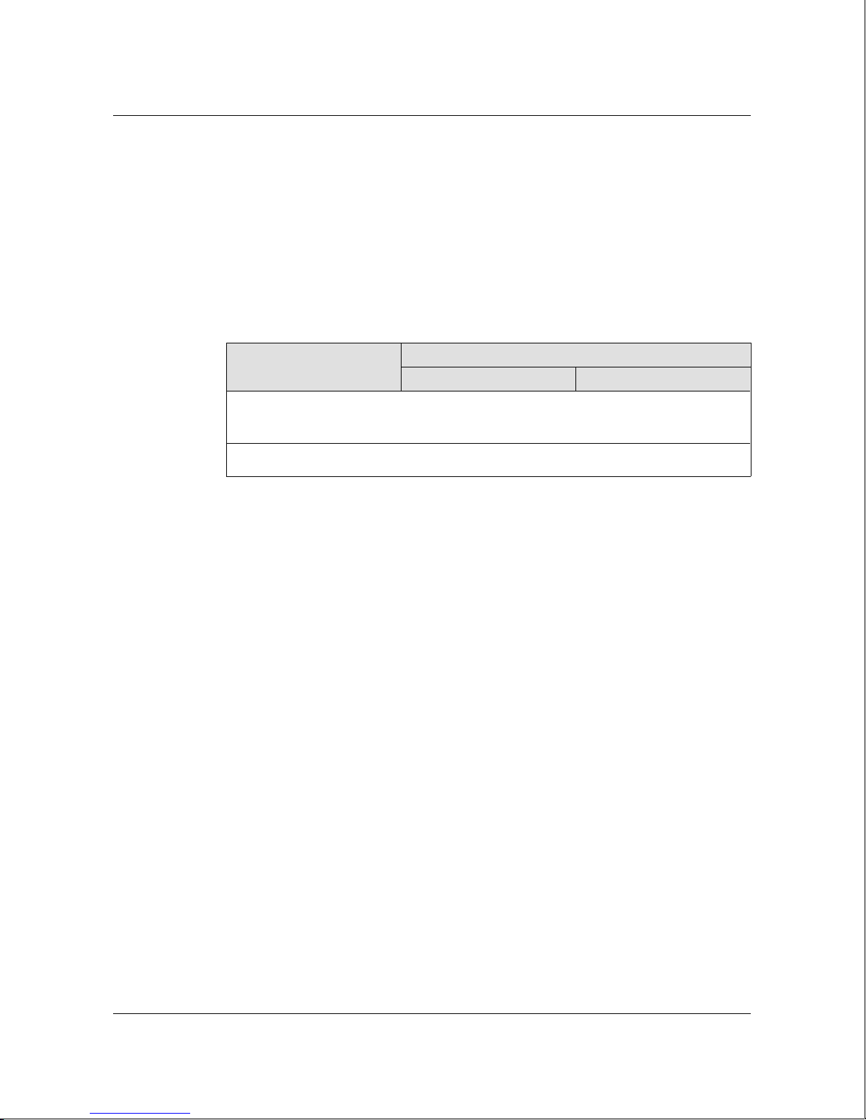
The following table shows the filtering capacity of a WaveSwitch 100 base
unit with sixteen fixed Ethernet ports and two FDDI feature modules.
Type of port
Ethernet (x 16) 14,880 238,000
FDDI (x 2) 150,000 300,000
Total for the WaveSwitch 100 538,000
The forwarding rate of a WaveSwitch 100 is 150,000 packets per second for
short packets, and 100 Mbps for long packets.
Filtering ca paci ty in packe ts per sec ond
Per port All ports
WaveSwitch 100 management
Simple Network Management Protocol (SNMP) is used to manage a
WaveSwitch 100. Management conforms to the Internet Engineering Task
Force (IETF) bridge management standard, RFC 1493.
Any configuration that is valid for a standard multiport transparent bridge is
valid for a WaveSwitch 100. Network administrators can apply knowledge
gained managing standard bridges to a WaveSwitch 100. Third-party
management applications that have embedded knowledge of the standard
bridge management informat ion base (MIB), RFC 1493, can be used with a
WaveSwitch 100.
The standard MIB reads port and switch statistics and specifies special
filtering or routing for individual destinat ion addresse s. Additional
management capability is possible by incorporating the WaveSwitch 100
Private MIB into the management station.
For information about using SNMP with the WaveSwitch 100, see
“Managing a WaveSwitch 100 Ethernet Switch” on page 47.
2 WaveSwitch 100 Ethernet Switch User Manual 12195
Page 25

Mission-critical applications
The IEEE 802.1d Spanning Tree Protocol provides support for
mission-critical configur ations. In mission-crit ical configur ations, two ports
of a WaveSwitch 100 Ethernet Switch—or two ports of different
WaveSwitch 100 Ethernet Switches—are connected to a single LAN to
create redundancy needed for fault tolerance. The Spanning Tree Protocol
prevents data traffic from circulating endlessly in closed loops created by
these connections.
Even in deliberately non-redundant networ ks, the Spanning Tree Protocol
prevents disastrous traffic loops when bridges are connected accidentally to
form physical loops.
For more information about using a WaveSwitch 100 in mission-critical
network configurations, see the WaveSwitch 100 Ethernet Switch
Configuration Guide.
Other features
The WaveSwitch 100 Ethernet Switch supports:
Introduction
• IEEE 802.1d Spanning Tree Protocol
• IP fragmentation with FDDI
• frame translation between Ethernet and FDDI according to
RFC 1042 and IEEE 802.1h
• SNMP management
• VT-100 access to comprehensive management functions through
Telnet or a local RS232 port
• EEPROM (flash) software permitting upgrades in the field
• software upgrade inband using TFTP, or out-of-band using the
front-panel RS232 port
• comprehensive indicator lamps (LEDs) that display the status of the
WaveSwitch 100 and individual ports
• automated self-te sts that run when the unit is powered on
• ongoing operation tests on connected equipment to assess network
integrity
WaveSwitch 100 Ethernet Switch User Manual 3
Page 26

Page 27

Installing a WaveSwitch 100 Ethern et Switch
This chapter describes the requirements and procedures for installing a
WaveSwitch 100 Ethernet Switch.
It gives details about how to connect the unit to the network, how to read the
front panel indicator lamps, how to install optional feature modules, and
how to replace the power supply.
This chapter contains the following sections:
• Package contents 6
• Front panel layout of a WaveSwitch 100 Ethernet Switch 7
• Component handling precautions 9
• Tools and materials 11
• Installation options 12
• Connecting power to a WaveSwitch 100 Ethernet Switch 13
• Connecting a WaveSwitch 100 Ethernet Switch to the network 14
• Reading the indicator lamps on a WaveSwitch 100 base unit 18
• Installing optional feature modules 21
– Installing and monitoring an FDDI feature module 23
– Installing and monitoring a 100Base-TX P1 feature module 25
– Installing and monitoring a 100Base-FX P1 feature module 27
– Installing and monitoring a 100Base-TX P4 feature module 29
– Installing and monitoring a 100VG-AnyLAN P5
feature module 31
– Installing and monitoring a WaveBus feature module 33
– Installing and monitoring a 10Base-T P4 feature module 35
• Replacing the power supply 37
• Troubleshooting guide 38
• Getting technical assistance 44
• General specifications 45
WaveSwitc h 100 Ethe rn et Swit ch12195User Manual
WaveSwitch 100 Ethernet Switch User Manual 5
Page 28

Package contents
Package contents
The WaveSwitch 100 Ethernet Switch is shipped as follows:
• WaveSwitch 100 base unit with power supply and
EIA rack-mounting brackets installed
• approved IEC power cord
• self-adhesive rubber feet (4)
• WaveSwitch 100 software distribution diskette
• WaveSwitch 100 Ethernet Switch Quick Hook-up Guide
• WaveSwitch 100 Ethernet Switch User Manual
• WaveSwitch 100 Ethernet Switch Configuration Guide
The WaveSwitch 100 base unit has two slots for optional feature modules.
If you ordered feature modules with a WaveSwitch 100 base unit, they
might have been installed at the factory.
If the feature modules were not installed at the factory, or were ordered as
an upgrade, you will have to install them on site. See “Installing optional
feature modules” on page 21.
6 WaveSwitch 100 Ethernet Switch User Manual 12195
Page 29
Front panel layout of a WaveSwitch 100 Ethernet Switch
Front panel layout of a WaveSwitch 100 Ethernet Switch
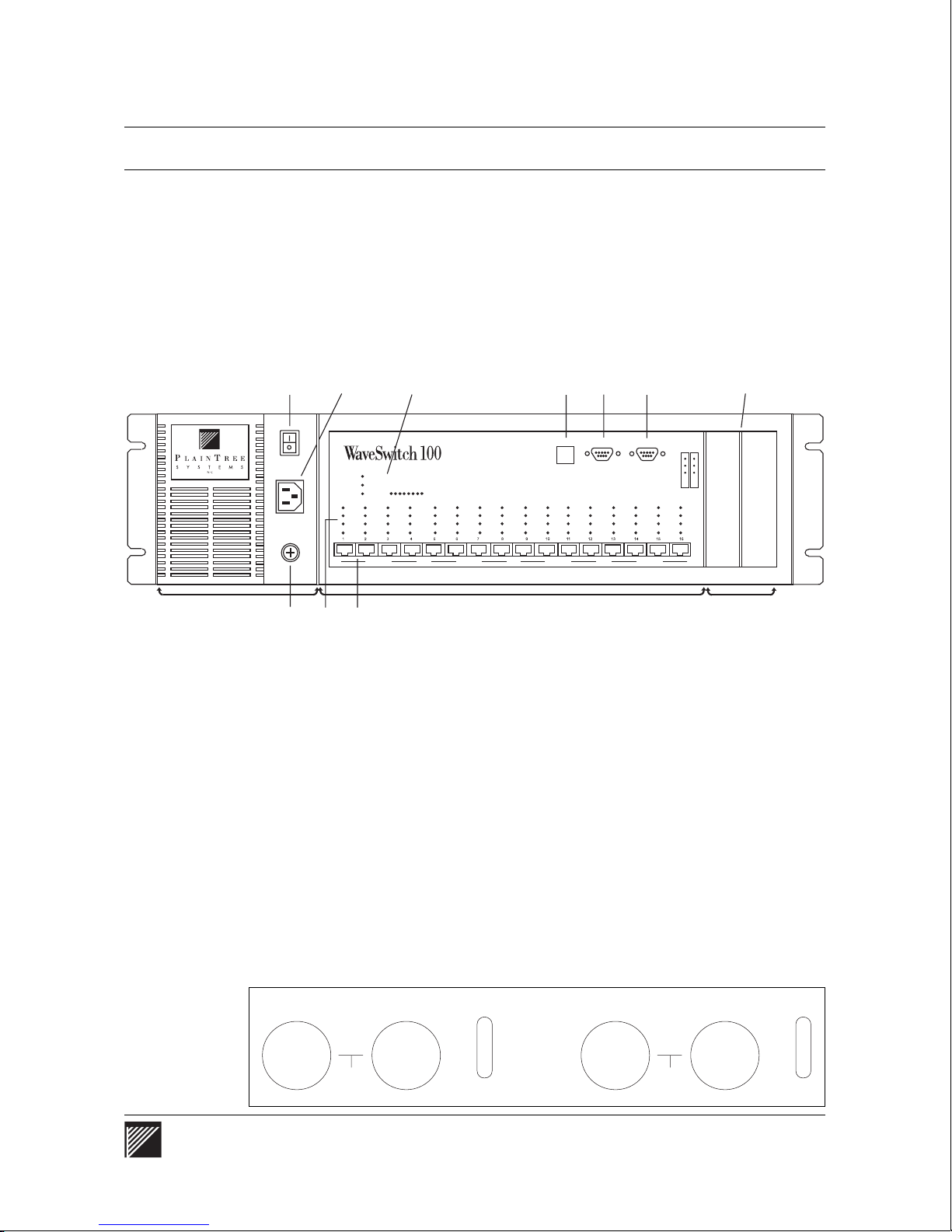
Figure 1 shows the front panel of a WaveSwitch 100 Ethernet Switch.
Note: WaveSwitch 100 base units are available with 8 or 16 fixed
Ethernet ports (10Base-T) or 12 fixed fiber-link (10Base-FL) Ethernet
ports (Figure 2). Except for the number and type of fixed ports, the
operation and feature s of the units are the same.
Figure 1
Front panel layou t of a Wav eSw itch 100 Eth ern et Switc h
Power supply
1
2
MAX LOAD
ERROR
LINK
DATA
COL
POWER
ERROR
ERROR
4
16-PORT ETHERNET SWITCH
SYSTEM LOAD FPS
ERROR
ERROR
ERROR
LINK
LINK
DATA
DATA
COL
COL
MDI-X MDI-X MDI-X MDI-X
LINK
LINK
DATA
DATA
COL
COL
ERROR
ERROR
ERROR
LINK
LINK
LINK
DATA
DATA
DATA
COL
COL
COL
ERROR
7
IDENTIFY
PC/MODEM
ERROR
ERROR
ERROR
LINK
LINK
LINK
LINK
DATA
COL
DATA
DATA
DATA
COL
COL
COL
ERROR
98
TEST
ERROR
ERROR
LINK
LINK
DATA
DATA
COL
COL
Ethernet ports
356
1 Power switch
2 IEC power entry connector
3 Power supply latch screw
4 WaveSwitch 100 status indicator lamps
5 Port indicator lamps: one set for each fixed port
6 Ports: 8 (100-8), 12 (100-FL), or 16 (100-16)
7 IDENTIFY button
8 PC/MODEM port (RS232, 9-pin)
9 TEST port (RS232, 9-pin)
10 Slots for optional feature modules (2)
10
OPTION SLOT
BASE PORT
17 21
ERROR
LINK
LINK
DATA
DATA
COL
COL
Slots for optional
feature modules
Figure 2
10Base-FL ports
TX RX
ERR
LNK
DAT
COL
1
TX RX
3
ERR
LNK
DAT
COL
WaveSwitch 100 Ethernet Switch User Manual 7
Page 30

Front panel layout of a WaveSwitch 100 Ethernet Switch
Figure 3 shows a top view of a WaveSwitch 100. The bumper in front of
the power supply extends beyond the face of the unit to help protect cables
and connectors from damage. The bumper provides space in front of the
faceplate to keep cabinet doors from closing against installed Ethernet
cables and fiber-optic cables and connectors, which can be easily damaged.
To see the faceplates, descriptions, and specifications of optional feature
modules, see the sections in this chapter about installing the modules
starting on page 21.
Figure 3
Top view of a WaveSwi t ch 100 Ethernet Sw itch
Bumper
Faceplate
8 WaveSwitch 100 Ethernet Switch User Manual 12195
Page 31

Component handling precautions
Handling optional feature modules
The WaveSwitch 100 base unit has two slots for optional feature modules.
If you ordered feature modules with a WaveSwitch 100 base unit, they
might have been installed at the factory.
If the feature modules were not installed at the factory, or were ordered as
an upgrade, you will have to install them on site.
To install or change feature modules, follow the procedures in “Installing
optional feature modules” on page 21.
DANGER — Power off the WaveSwitch 100 and disconn ect the AC power
cord before you remove or inst all feature modules. Failure to do so could
cause personal injury or damage to the circui ts of the feature mod ules or the
WaveSwitch 100.
You can make network connections on the front panel while the
WaveSwitch 100 is operating, but you must power off the unit to remove or
install modules.
Component handling precautions
CAUTION — Make sure you know how to handl e electroni c comp onen ts
correctly before you begi n install ing the WaveS witch 100. Incorrect handling
can cause damage to static-sensi ti ve comp onen ts.
To avoid possible damage to circuit cards by electrostatic discharge (ESD),
use the following precautions:
• Wear an anti-static wrist strap when handling circuit cards (featur e
modules). Connect the wrist strap to the chassis of the unit after you
remove the cover.
• Keep circuit cards in their anti-static bags until they are ready to be
installed.
• Remove circuit cards from their anti-stati c bags and install them
directly into the unit. Do not pass circuit cards to another person.
• If you need to put a circuit card down, put it back into the anti-static
bag.
• Handle circuit cards by their edges only. Do not touch the electronic
components or any exposed printed circuitry.
• Limit your movement to reduce static-electricity buildup.
WaveSwitch 100 Ethernet Switch User Manual 9
Page 32

Component handling precautions
Han dling fibe r-optic cable
DANGER — Do not look into the end of fiber-optic cab le. The light source
used in fiber-optic cables can damage your eyes.
CAUTION — Make sure you know how to handle fiber-optic cabl e correctly.
Incorrect handling can cause damage to the glass fiber.
Although the glass optical path of fiber-opti c cable is protected with
reinforcing materi al and plastic insulation, follow these precautions to avoid
damaging the glass fiber:
• Do not kink, knot, or vigorously flex the cable
• Do not bend the cable to less than a 3-inch radius
• Do not stand on fiber-optic cable; keep the cable off the floor.
• Do not pull fiber-optic cable any harder than you would a cable
containing copper wire of comparable size
• Do not allow a static load of more than a few pounds on any section
of the cable
Overstressing fiber-optic cable may not result in immediate failur e of the
cable; however, progressive degeneration can occur. If you suspect damage
to the cable, either through known mishandling or by indication of an
abnormally high error rat e in one direction, rever se the cable pairs. If the
high error rate appears in the other direction, replace the cable.
10 WaveSwitch 100 Ethernet Switch User Manual 12195
Page 33

Tools and materials
You need some tools and materials that are not supplied with the unit to do
some of the procedures in this manual.
For rack mounting a WaveSwitch 100 bas e unit
• rack-mounting scre ws (4) that are compatible with the rack
equipment you are using
• screwdriver for the rack-mounting screw s
For connecting a WaveSwitch 100 base unit to the network
• for base units with 10Base-T Ethernet ports
– standard cables (Category 3 required, Category 5 recommended)
to connect ports to network stations (See Table 2 on page 15)
– crossover cables to connect ports to network equipment
such as repeater/hubs, routers, or bridges
(See Table 1 on page 15)
• for base units with 10Base-FL Ethernet ports
– duplex 62.5/125 micron FDDI-grade mul timode fiber- optic
cables with ST-style connectors to connect 10Base-FL ports
to network equipment (See page 16)
Tools and materials
For connecting ports of high-speed feature modules to the network
See the installation procedures for optional feature modules in this chapter.
For connectin g the local con sole to th e base unit (o pt ion al)
• a straight-thr ough RS232 cable with 9-pin male D-subminiature
plugs at both ends for connecting a VT100 terminal or terminal
emulator to the WaveSwitch 100. See page 49.
For installing or removing optional feature modules
• Phillips screwdriver (#2)
• 1/4-inch nutdriver (#4) or wrench
For replacing the power supply
• Phillips screwdriver (#2)
WaveSwitch 100 Ethernet Switch User Manual 11
Page 34

Installation options
Installation options
The WaveSwitch 100 can be installed in a standard 19-inch EIA RS-310C
equipment rack, or in an IEC Pub 297 equipment rack. It can also be put on
a horizontal surface with a minimum area of 44 cm x 44 cm
(17.5 in. x 17.5 in.) that can support 12.3 kilograms (27 pounds).
Equipment rack installation
Choose the rack position in which you want to install the unit. Use four
mounting screws (provided with your equipment rack) to secure the unit by
its mounting brackets to the rack.
Note: There is no requirement to leave space on the rack between the
WaveSwitch 100 and adjacent equipment. However, you may want to
leave space for cabling above or below the unit, depending on your
cabling requirements.
CAUTION — Do not use the WaveSwitch 100 chassis to support other
equipment when it is mounted in the equipmen t rack. Doing so could
overload the rack mounting brackets and damage the unit.
If you plan to supply AC power to the unit using a rack-mounted power
strip, make sure that the AC supply and wiring are not overloaded and that
reliable earth grounding is maintained.
If you are installing a WaveSwitch 100 in an enclosed equipment rack,
make sure the internal environment of the rack is within the temperature and
humidity limits specified in “General specifications” on page 45.
Note: To make the unit lighter during installation, you can temporarily
remove the power supply. Use the procedure on page 37.
Freestanding installation
If you are installing a WaveSwitch 100 as a freestanding unit, apply the four
self-adhesive rubber feet to the bottom of the chassis. Make sure the bottom
surface of the chassis is clean and dry. Stand the chassis on either side and
apply one rubber foot 2.5 centimeters (1 inch) from each corner.
You can remove the two EIA mounting brackets by removing the two
mounting screws that secure each bracket to the chassis.
12 WaveSwitch 100 Ethernet Switch User Manual 12195
Page 35

Connecting power to a WaveSwitch 100 Ethernet Switch
Connecting power to a WaveSwitch 100 Ethernet Switch
Make sure the power switch on the front of the unit is in the off ( O )
position.
Plug one end of the power cord supplied with the WaveSwitch 100 into the
IEC power entry connector on the front of the unit.
Plug the other end of the power cord into a grounded AC outlet. For more
information about power requir ements and environmental requi rement s, see
“General specificatio ns” on page 45.
Apply power by setting the power switch to the on ( I ) position.
WaveSwitch 100 Ethernet Switch User Manual 13
Page 36
Connecting a WaveSwitch 100 Ethernet Switch to the network
Connecting a WaveSwitch 100 Ethernet Switch to the network
The fixed Ethernet ports on the base unit enable connection of a
WaveSwitch 100 Ethernet Switch to 10-Mbps repeater/hubs or network
stations.
Base units are available with one of two types of fixed Ethernet ports:
• 10Base-T (8 or 16 ports)
• 10Base-FL (12 ports)
For information about connecting high-speed ports to the network, see the
installation procedures for the optional feature modules.
For information about network configurat ions, see the WaveSwitch 100
Ethernet Switch Configuration Guide.
10Base-T ports
10Base-T ports require two t w ist ed pair s of wir es to carry network data.
Each pair of wires carries data in one direction.
Tables 1 and 2 on page 15 show the signal connections for two pairs of
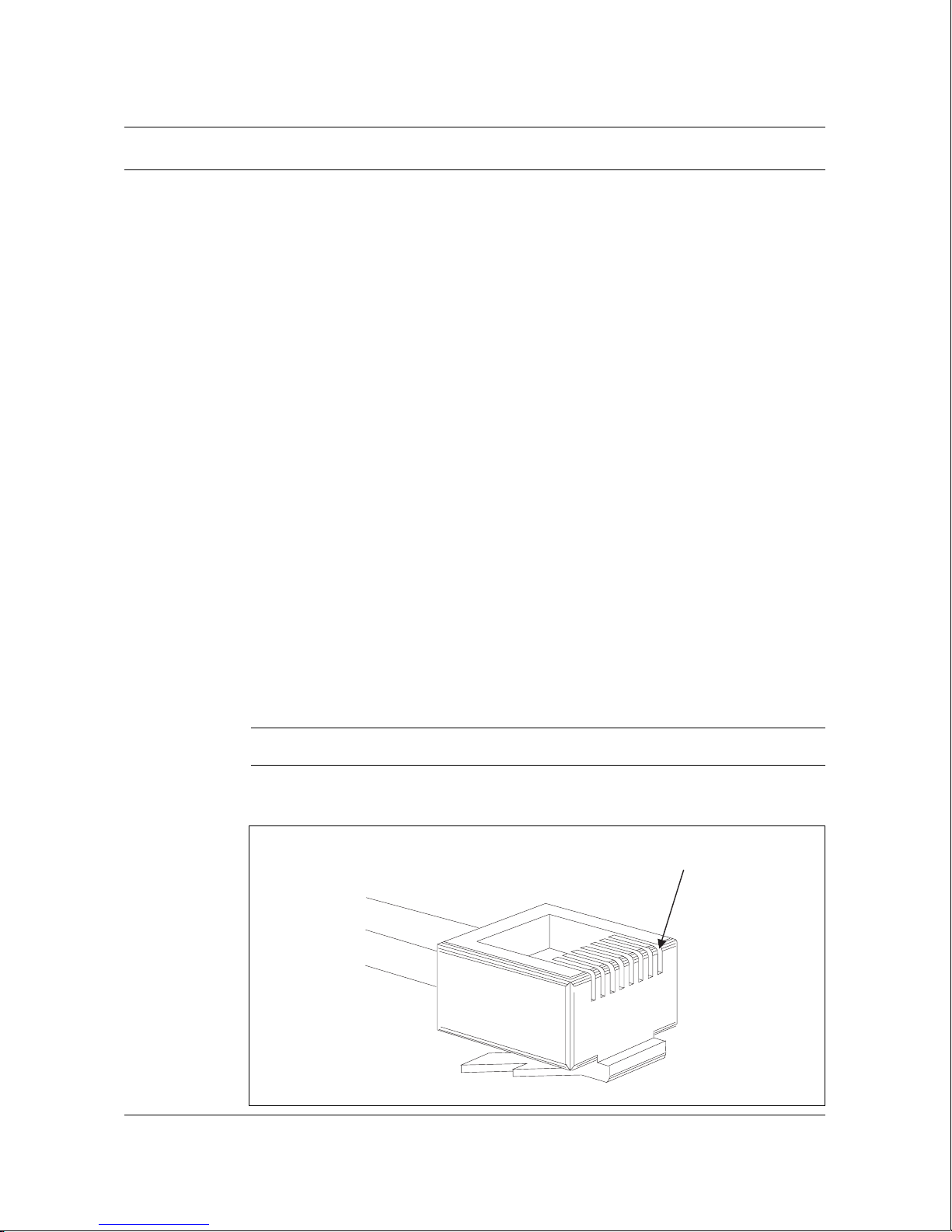
wires in crossover and straight-through cables. Figure 4 shows the location
of pin 1 on an RJ-45 plug.
Note: Because UTP cable with four twisted pairs of wires is normally
used in cabling, the remaining four pins on the RJ-45 plug are typically
used for telephone connections.
CAUTION—Do not connect WaveSwitch 100 data plugs to a telephone line.
Figure 4
Location of pin 1 on an RJ-45 plug
Pin 1
14 WaveSwitch 100 Ethernet Switch User Manual 12195
Page 37
Connecting a WaveSwitch 100 Ethernet Switch to the network
Connecting a 10Base-T port to an Ethernet repeater/hub
or to another WaveSwitch 100
To connect a 10Base-T port on a WaveSwitch 100 to a 10Base-T
repeater/hub, or to another WaveSwitch 100, use a 10Base-T crossover
cable.
Note: The MDI-X labels below the Ethernet ports mean that the ports
normally accept crossover cables.
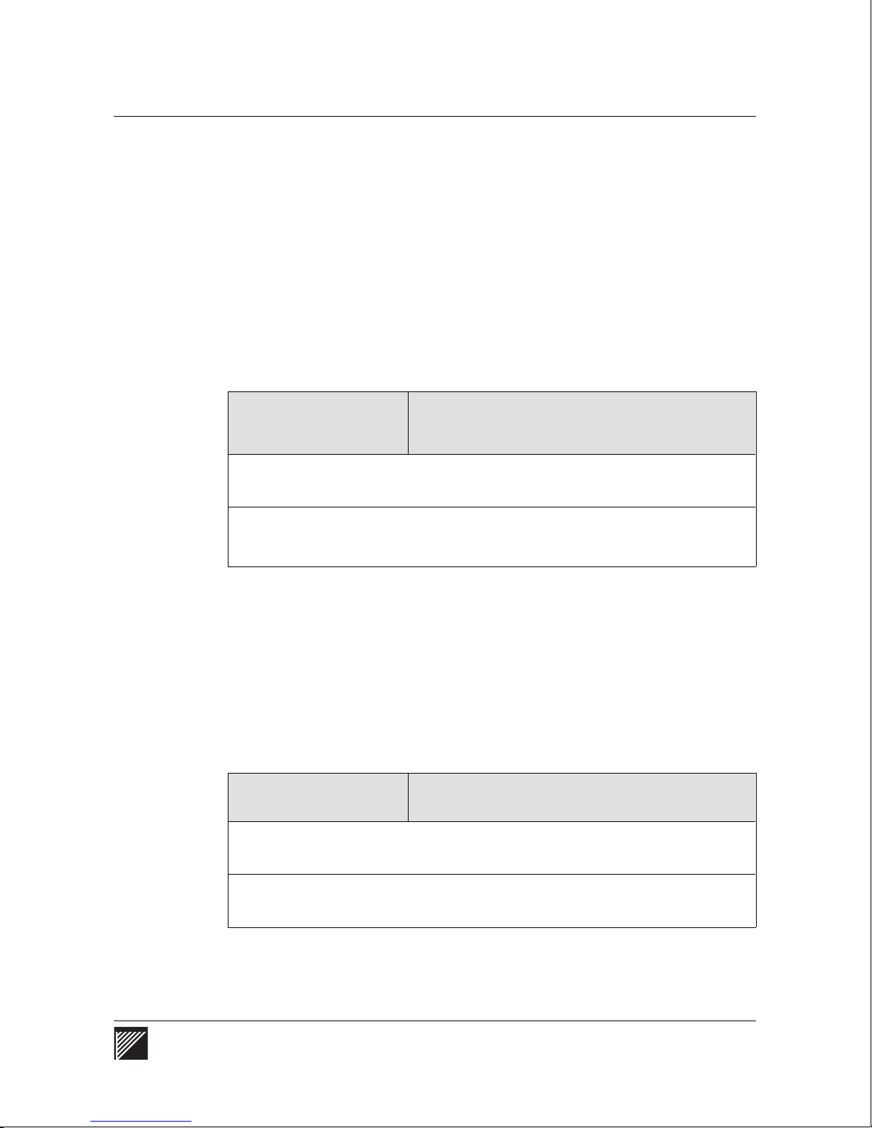
A 10Base-T crossover cable connects pair 1 at one end of the cable to pair 2
at the other end of the cable; that is, pair 1 and pair 2 are crossed (Table 1).
Table 1
Signal connection s for a 10Base-T crossove r cable
Pin number on the RJ-45 connector
Wire pair (functi on)
Pair 1 (received data) 1 (RD+) 3 (TD+)
Pair 2 (transmitted data) 3 (TD+) 1 (RD+)
WaveSwitch 100
2 (RD-) 6 (TD-)
6 (TD-) 2 (RD-)
Repeat er/ h u b or
WaveSwitch 100
Connecting a 10Base-T port to a network station
To connect a 10Base-T port on a WaveSwitch 100 to a network station, use
a 10Base-T straight-through cable.
A 10Base-T straight-through cable connects the pins at one end of the cable
to the same pins on the connector at the other end of the cable (Table 2).
Table 2
Signal connection s for a 10Base-T straight -through ca bl e
Pin number on the RJ-45 connector
Wire pair (functi on)
Pair 1 (received data) 1 (RD+) 1 (TD+)
WaveSwitch 100 Network station
Pair 2 (transmitted data) 3 (TD+) 3 (RD+)
2 (RD-) 2 (TD-)
6 (TD-) 6 (RD-)
WaveSwitch 100 Ethernet Switch User Manual 15
Page 38
Connecting a WaveSwitch 100 Ethernet Switch to the network
Making a 10Base-T adapter cable
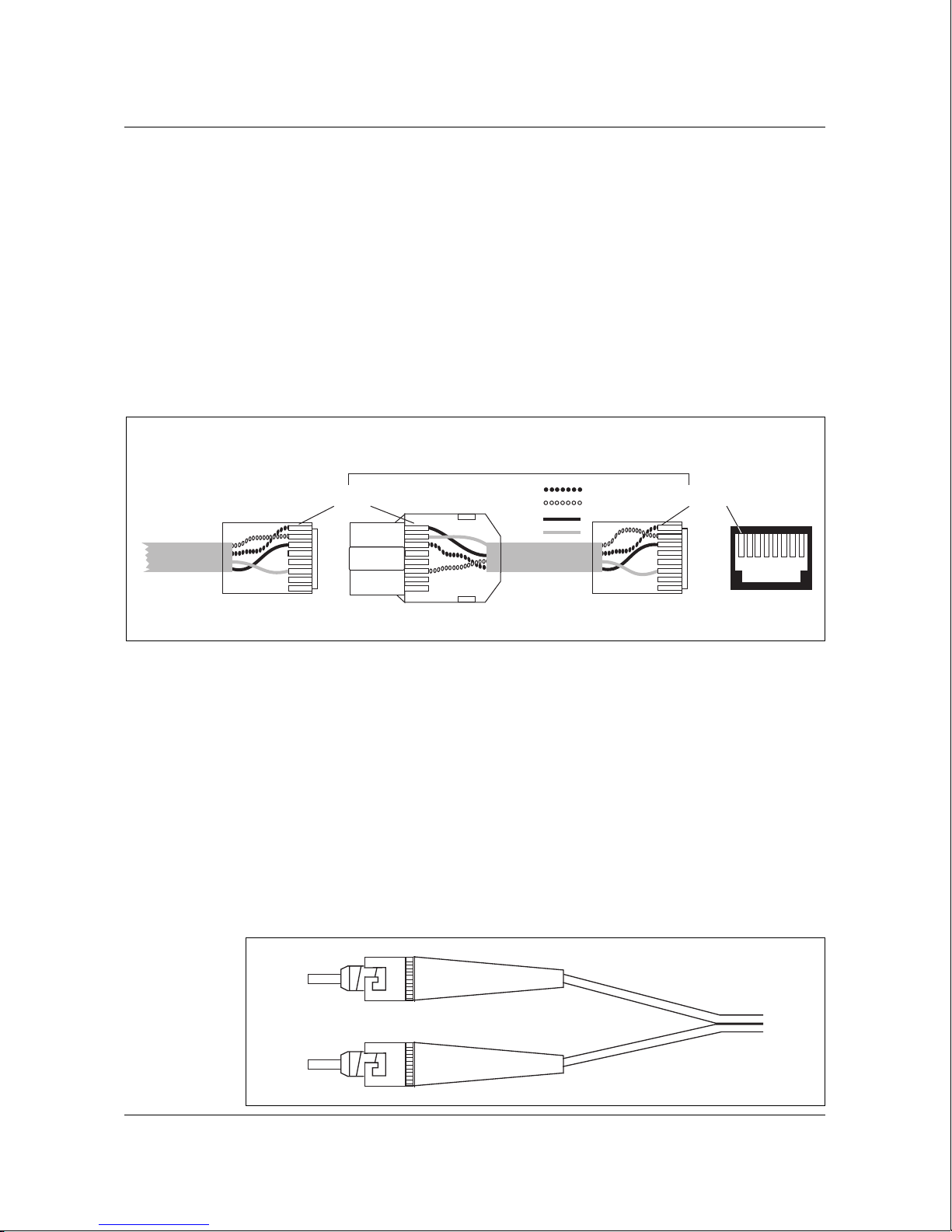
If you do not have a straight-thr ough cable, you can use an adapter cable
and a 10Base-T crossover cable in series to connect a network station to an
Ethernet port. See Figure 5.
To make an adapter cable, wire a short crossover cable so it has an RJ-45
plug at one end and an RJ-45 jack at the other end. When you plug the
adapter cable into an Ethernet port, then plug a 10Base-T crossover cable
from a network station into the jack of the adapter cable, you reverse the
pairs of wires, effectively creati ng the wiring of a straight-thr ough cable.
Figure 5
Using an adapter cable to mak e straight-thr ough conne ction s
Crossover cable
10Base-FL ports
Adapter cable
RD +
RD TD +
TD -
Pin 1Pin 1
10 Base-T
switch port
10Base-FL ports use duplex (two fiber) fiber-optic cable; each fiber, which
carries data in one direction, terminates with an ST-style connector. See
Figure 6.
10Base-FL ports have an 820 nm LED light source and can transmit data up
to 2000 meters (6560 feet) with 62.5/125 micron graded-index fiber- optic
cable.
The minimum transmitter output power for 10Base-FL ports is -12 dBm; the
maximum receiver sensitivity is -32.5 dBm.
Figu re 6
One end of a duplex f ib er-opt i c cable term i nati ng w ith tw o ST-styl e connec tor s
16 WaveSwitch 100 Ethernet Switch User Manual 12195
Page 39
Connecting a WaveSwitch 100 Ethernet Switch to the network
Connecting the PC/MODEM serial port
The PC/MODEM serial port is a standard RS232 port that enables
connection to a local console for configuring the WaveSwitch 100 and
doing network management operations.
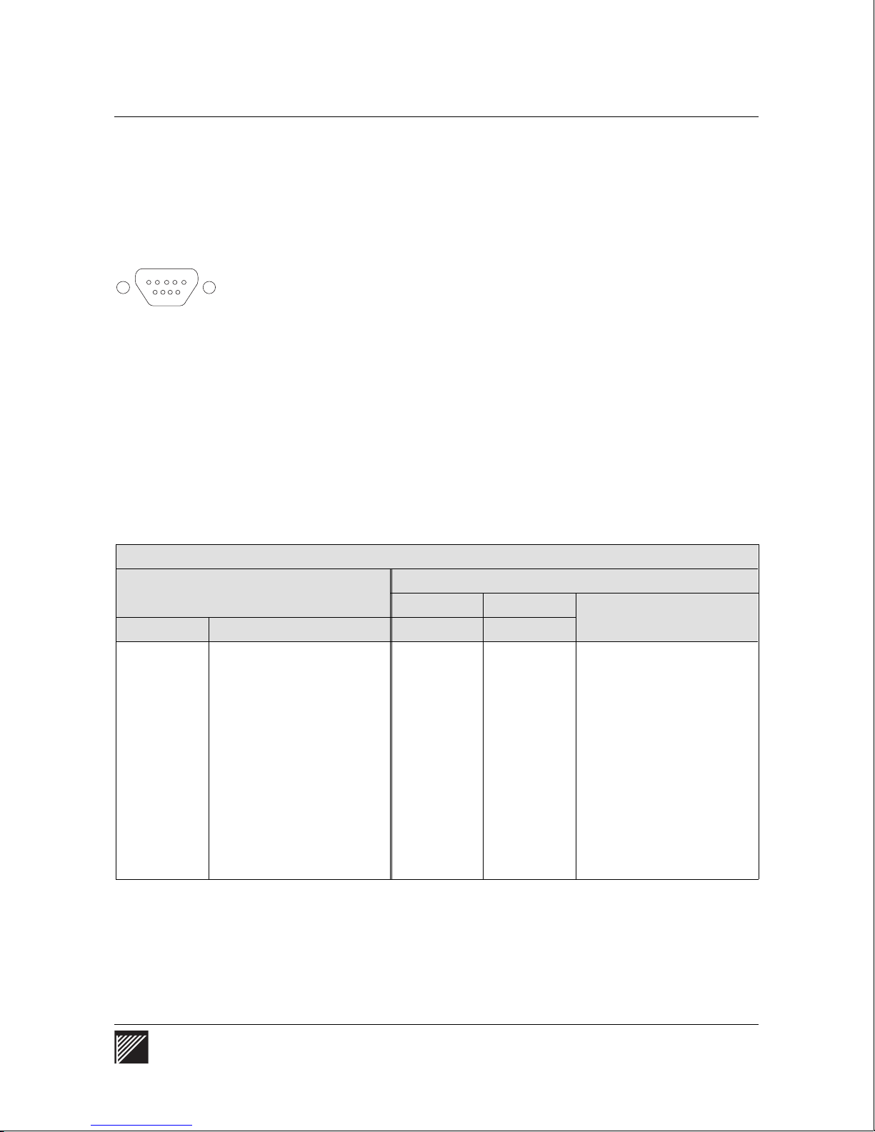
PC/MODEM
9-pin D-subminiature male connector at one end and an appropriate
connector on the other end to attach to the console terminal. If the terminal
to which you are connecting has a 25-pin connector, you can use a 9-pin to
25-pin adapter cable between the WaveSwitch 100 and the console. The
cable must not be longer than 16 meters (50 feet).
Note: For information about the console, see “Managing a WaveSwitch
100 Ethernet Switch” on page 47.
Table 3 shows the required connections between the WaveSwitch 100 and a
terminal for 9-pi n to 9-pin and 9-pin to 25-pin cables. Commercially
available straight-thr ough RS232 cables that have all nine signals connected
meet the criteria.
Table 3
Signal con nect ions f or the ser i al cabl e
Connector on
VT100 terminal or VT100 emulator
The preferred interconnect cable is a straight-through RS232 cable with a
WaveSwitch 100
Pin number Signa l (abbr evi ati on) Pin number Pin number
9-pin 25-pin
Signal (ab bre vi ati on)
1 not used 1 — not used
2 transmitted data (TD) 2 3 received data (RD)
3 received data (RD) 3 2 transmitted data (TD)
4 not used 4 — not used
5 signal ground (SG) 5 7 signal ground (SG)
6 not used 6 — not used
7 clear to send (CTS) 7 4 request to send (RTS)
8 request to send (RTS) 8 5 clear to send (CTS)
9 not used 9 — not used
About the TEST port
The TEST port is used during production only. The test port should not be
connected during normal operation of the unit.
WaveSwitch 100 Ethernet Switch User Manual 17
Page 40

Reading the indicator lamps on a WaveSwitch 100 base u nit
Reading the indicator lamps on a WaveSwitch 100 base unit
When the WaveSwitch 100 is powered on, the indicator lamps on the front
panel give a visual indication of the operating status of the unit.
The indicator lamps are grouped to show:
• the general status of the unit
• the status of each port and module
When the WaveSwitch 100 is powered on, all the red ERROR indicator
lamps and the SYSTEM LOAD FPS lamps normally come on. These
indicator lamps stay on until the diagnostic self-tests, which run
automatically when the unit is powered on, are completed. The testing
cycle takes about 40 seconds.
If no errors are detected, the ERROR indicator lamps go off and the
WaveSwitch 100 is operational.
Monitoring the status of the WaveSwitch 100
Three indicator lamps labeled POWER, ERROR, and MAX LOAD, and an
eight-lamp display labeled SYST EM LOAD FPS, give informat ion about
the status of the unit.
POWER
ERROR
MAX LOAD
POWER
The green indicator lamp labeled POWER comes on and stays on when the
power switch is in the on ( I ) position.
The POWER lamp indicates that the internal power supply is providing
electrical power to the circuit boards in the unit.
ERROR
The red ERROR indicator lamp always comes on when the WaveSwitch
100 is powered on. After the start-up self-tests are completed, the ERROR
lamp normally goes off. The lamp stays on if a hardware-related err or is
detected on the motherboard.
The ERROR lamp blinks steadily if the software in ROM is corrupted and
new information needs to be downloaded.
The ERROR lamp flashes a code, made up of three groups of flashes
separated by pauses, if one of the start-up self-tests has failed. The
flashcode helps technical support staff identify the problem.
The ERROR indicator lamp remains in one of the three modes described
above until the WaveSwitch 100 is powered off.
18 WaveSwitch 100 Ethernet Switch User Manual 12195
Page 41
Reading the indicator lamps on a WaveSwitch 100 base unit
MAX LOAD
The MAX LOAD indicator lamp always comes on when the WaveSwitch
100 is powered on. After the start-up self-tests are completed, the MAX
LOAD indicator lamp normally goes off.
The MAX LOAD indicator lamp comes on when the backplane is fully
utilized. This lamp stays on until utilization of the backplane falls below
one hundred percent.
SYSTEM LOAD FPS
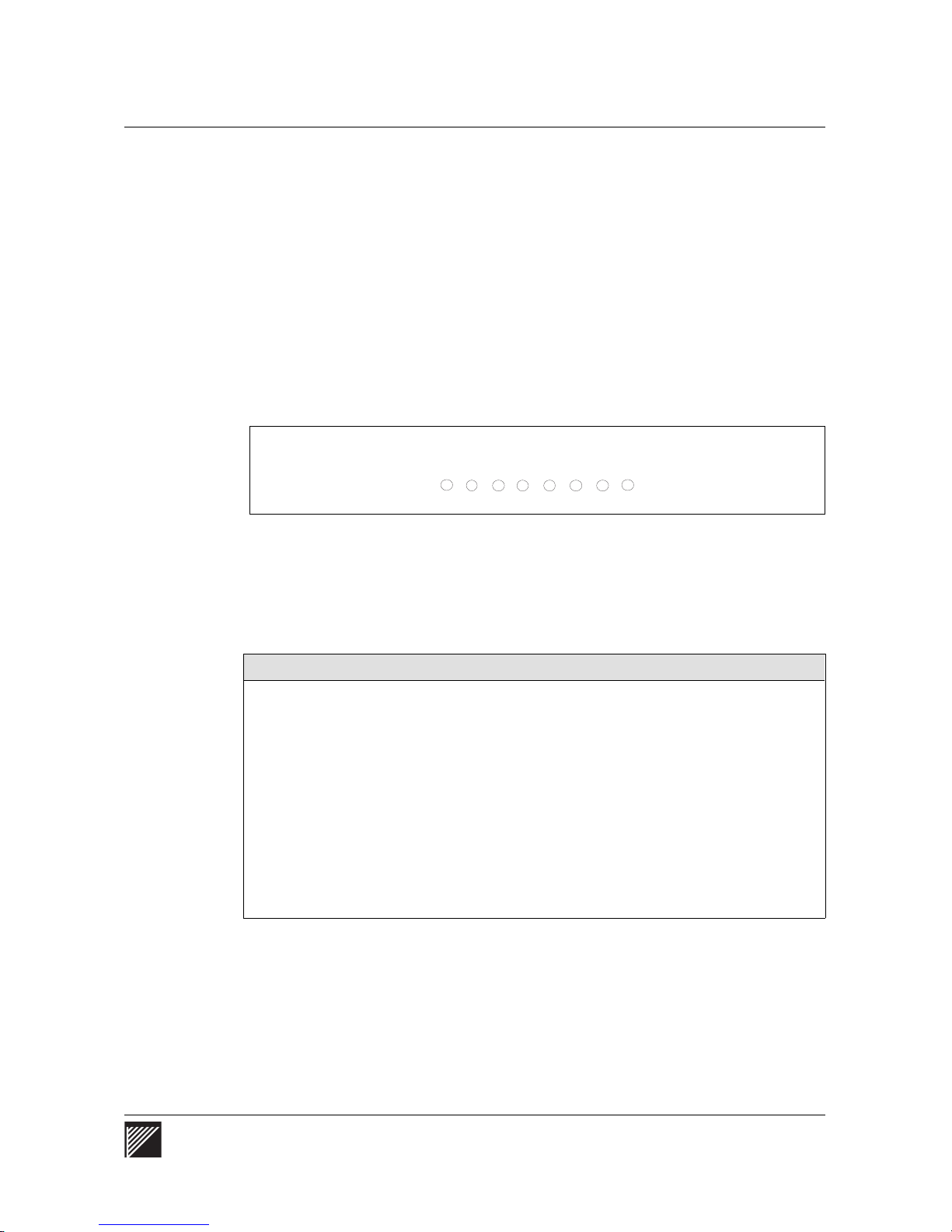
The SYSTEM LOAD FPS indicator lamps show the volume of transmission
traffic on the backplane of the unit in frames per second (FPS).
SYSTEM LOAD FPS
The eight lamps give a real-time indication of the volume of traffic in
frames per second. If there is no traffic on the backplane of the
WaveSwitch 100, none of the lamps comes on.
When data is present, the lamps come on, from left to right, as follows:
Indicator lamp Reporting range in frames per second
1 1 to 1199
2 1.2K to 2.4K
3 2.5K to 4.9K
4 5.0K to 9.9K
5 10.0K to 19.9K
6 20.0K to 39.9K
7 40.0K to 79.9K
8 over 80K
Note: Because long frames take more time than short frames, the
backplane can be fully utilized without the maximum number of frames
being used; this means the MAX LOAD lamp can come on without all
the SYSTEM LOAD FPS lamps being on.
WaveSwitch 100 Ethernet Switch User Manual 19
Page 42

Reading the indicator lamps on a WaveSwitch 100 base u nit
Monit oring the fix ed Et he rnet po rt s
There are four indicator lamps associated with each fixed Ethernet port on
the base unit—ERROR, LINK, DATA, and COL.
ERROR
The red ERROR indicator lamp always comes on when the WaveSwitch
100 is powered on. After the start-up self-tests are completed, the ERROR
lamp normally goes off.
The ERROR lamp stays on if the electrical loopback test failed.
ERROR
LINK
DA TA
COL
If four adjacent ERROR indicator lamps come on and stay on, an error was
detected on the bridge-circuit ASIC that control s that group of ports. For the
sixteen-port base unit, the port groups are: 1-4, 5-8, 9-12, and 13-16.
LINK
The green indicator lamp labeled LINK is normally on when the
WaveSwitch 100 is connected to a powered Ethernet station. The lamp
stays on to indicate that the port is connected and ready for operation.
If the station to which the WaveSwitch 100 is connected is powered off, the
lamp goes off.
DATA
The yellow indicator lamp labeled DATA comes on when the port is
receiving or transmitting data. Because the lamp responds to the flow of
data on the port, it normally comes on intermittently; however, if data traffic
on the port is heavy, the lamp can stay on for extended periods.
COL
The orange indicator lamp labeled COL (Collision) comes on when
outgoing (transmitted) data and incoming (receive) data collide. The lamp
goes off when the collision has been resolved on the port.
20 WaveSwitch 100 Ethernet Switch User Manual 12195
Page 43

Installing optional feature modules
The WaveSwitch 100 has slots to hold up to two optional feature modules.
CAUTION — Make sure you know how to handl e electroni c comp onen ts
correctly before installi ng a feature modu le. Incorrect hand ling can cau se
damage to static-sensit ive comp o nent s. See page 9.
It is necessary to access the top and the rear of the WaveSwitch 100 to
install the feature modules. If the unit is rack-mounted, you may need to
remove it from the rack to install the modules.
To install a feature module, follow the steps below.
Step Action
1
Set the power switch of the WaveSwitch 100 to the off ( O ) position
and disconnect the power cord from the AC outlet.
2 Using a Phillips screwdriver (#2), remove the three screws at the
rear of the unit that secure the top cover.
3 Slide the top cover towards the rear of the unit until the front edge
of the cover is exposed. Lift the cover off.
Installing optional feature modules
Note:
The two feature module slots are at the right side of the
chassis.
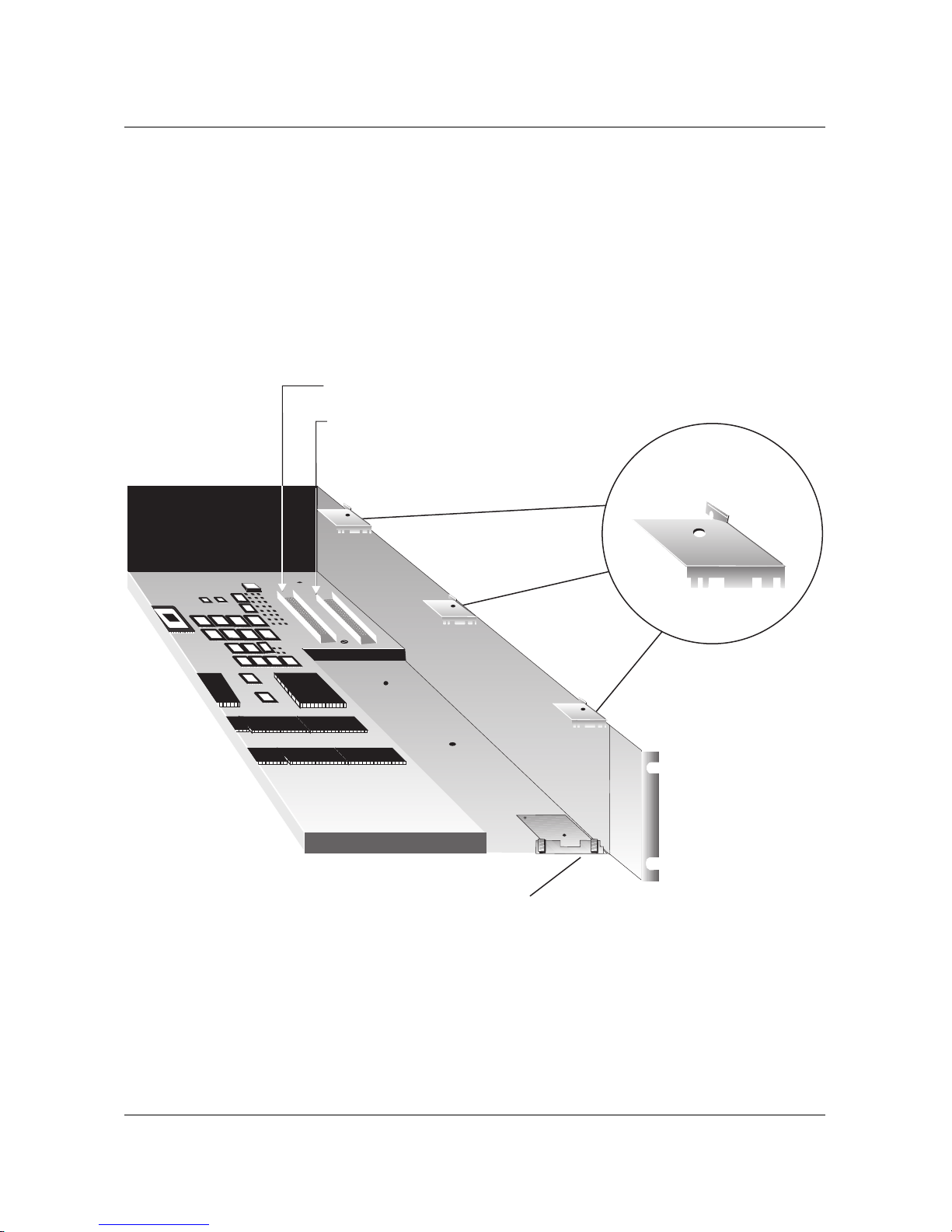
4 Remove the three module retaining clips that are located inside the
top right side of the chassis. To remove the clips, use a 1/4" nut
driver to loosen the mounting nuts; do not remove the mounting
nuts. Slide the clips up and off. See Figure 7.
5 Choose the slot you want to use and lift out the filler plate from its
notch in the module supporting bracket.
6 Align the module over the slot and lower the front of the module into
the chassis.
7 Insert the top of the module faceplate under the top lip of the front
faceplate, aligning the bottom with the module supporting bracket.
8 Lower the rear of the module into the chassis until it is level.
9 Align the connectors, and insert the module until it is fully seated.
10 Install the three module retaining clips, making sure that the featur e
module card rests in the correct notch in each of the clips. See
Figure 7. Tighten the mounting nuts.
11 Install the cover and screws, connect the AC power cord, and
power on the WaveSwitch 100.
end
WaveSwitch 100 Ethernet Switch User Manual 21
Page 44
Installing optional feature modules
Figure 7
Installin g option al featur e mo dul es
Connector for slot 1
Connector for slot 2
Module retaining clip (3)
Front panel
22 WaveSwitch 100 Ethernet Switch User Manual 12195
Module supporting bracket
Page 45
Installing and monitoring an FDDI feature module
Installing and monitoring an FDDI feature module
An FDDI feature module enables connection to an FDDI LAN. The
interface is compliant with ANSI X3T9 and supports a 100-Mbps
transmission rate up to 2000 meters (6560 feet). The feature module is
available configured as a SAS (single-attachment station) for connection to
a concentrator, or configured as a DAS (dual-attachment station) for direct
connection to an FDDI backbone. You can upgrade SAS modules to DAS
modules in the field with the SAS-to-DAS upgrade kit.
WaveSwitc h 100 Ethe rn et Swit ch12195User Manual
Tools and materials
You need the following tools to install an FDDI feature module:
• Phillips screwdriver (#2)
• 1/4-inch nutdriver (#4) or wrench
You need the following cabling to connect each port of an FDDI feature
module to the network:
• dual 62.5/125 micron graded-index multimode fiber -opti c cable with
a dual SC connector (AMP 503553-1 or equivalent)
Installing an FDDI feature module
To install an FDDI feature module, use the procedure on page 21.
Connecting to the network
FDDI ports connect to the network using a dual 62.5/125 micron
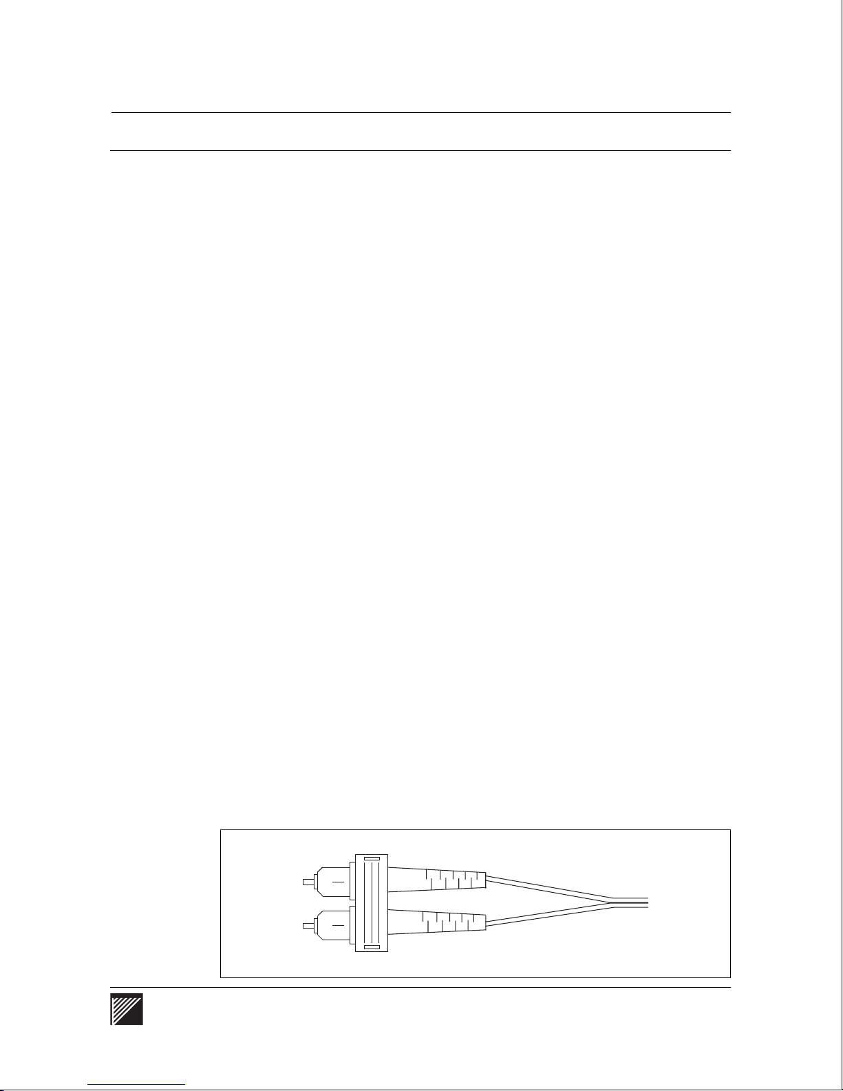
graded-index multimode fiber-optic cable fitted with a dual SC connector
(AMP 503553-1 or equivalent). Each port needs two connections: transmit
and receive. These connections are made simultaneously through the dual
jack on the faceplate of the module. See Figure 8.
SAS FDDI modules have one dual SC jack on the faceplate; DAS FDDI
feature modules have two dual SC jacks. SAS need one dual fiber-optic
cable to connect to the network. DAS need two dual fiber-optic cables to
connect to the network.
Figure 8
FDDI fiber-optic cable with a dual SC connect or
WaveSwitch 100 Ethernet Switch User Manual 23
Page 46
Installing and monitoring an FDDI feature module
Monitoring the indicator lamps
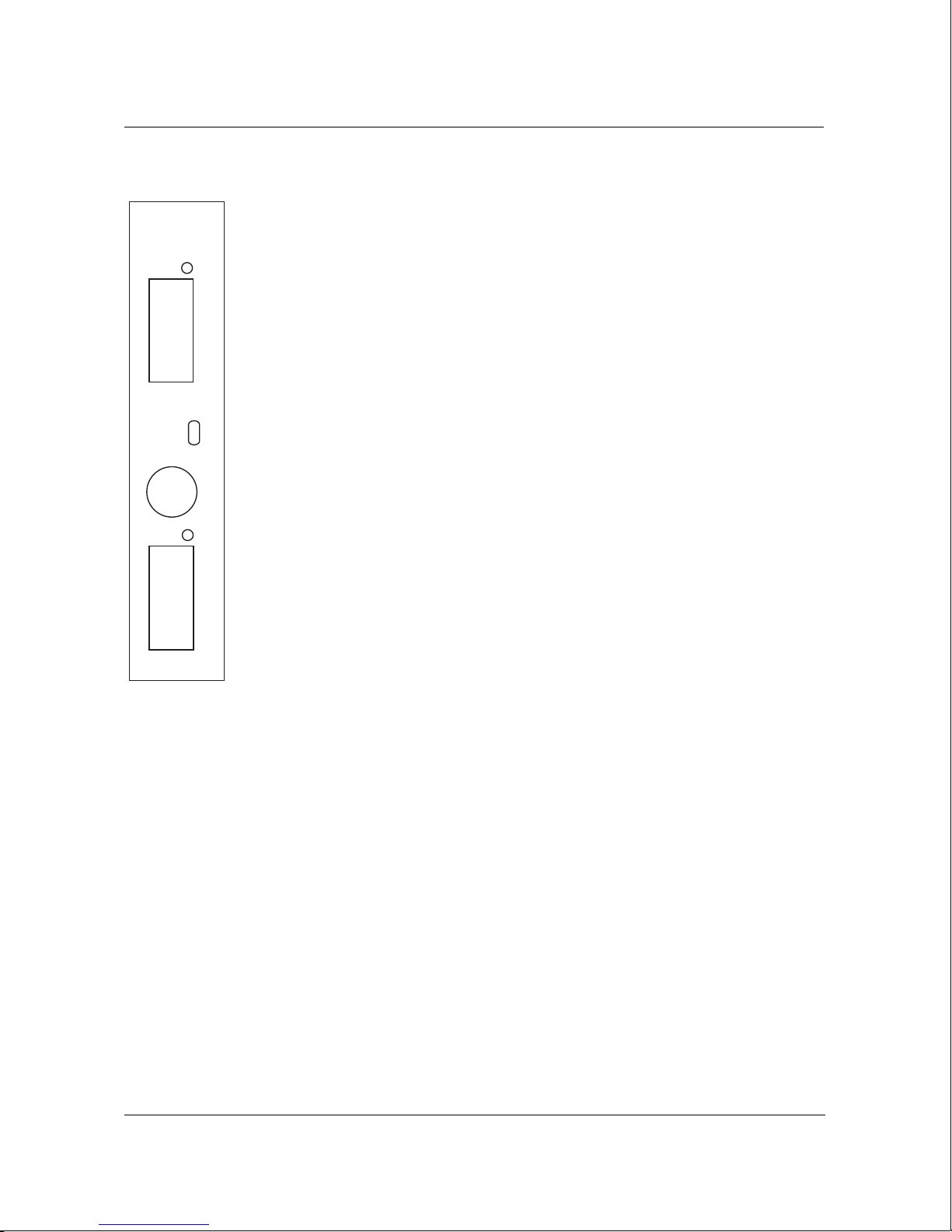
Each FDDI feature module has two indicator lamps labeled ERROR and
RG OP above the OPT BYPASS connector. Dual-attachment station (DAS)
modules have WRP A and WRP B indicator lamps installed on the faceplate
PTC212A
WRP B
of the module in addition to the ERROR and RG OP indicator lamps.
ERROR
The red ERROR indicator lamp always comes on when the WaveSwitch
B
100 is powered on. After the start-up self-tests are completed, the ERROR
lamp normally goes off.
1300nm
ERROR
RG OP
OPT BYPASS
WRP A
The ERROR indicator lamp stays on if a hardware error has been detected.
RG OP
The green RG OP (ring operational) indicator lamp comes on and stays on
when the connection to the FDDI ring is established. The RG OP lamp
blinks if the FDDI feature module becomes isolated from the ring.
WRP A and WRP B (installed on FDDI DAS modules only)
The yellow WRP (ring wrap) indicator lamps (WRP A and WRP B) stay off
during the WaveSwitch 100 start-up cycle and when normal network
A
connections are made (that is, when the green RG OP lamp stays on).
In most network configurations, the WRP A or WRP B lamp comes on and
stays on to indicate through which port the ring is wrapped. In dual-homed
configurations only, the ring wrap indicator lamp of the active port (A or B)
normally stays on.
Using the OPT BYPASS connector
The OPT BYPASS (optical bypass) connector accepts a 6-pin miniature
DIN plug to connect an optical bypass switch to the FDDI module. An
optical bypass switch allows the light to bypass the module to maintain the
operation of the FDDI ring should the module lose power or develop a fault.
Note: Plaintree Systems does not supply optical bypass switches.
Suitable models are made by AMP Incorporated, Harrisbur g, PA (FDDI
Dual Bypass Switch Module/shielded 6-pin Mini-DIN connector: AMP
501916-6), and DiCon Fiberoptics Inc, Berkeley, CA (FDDI Dual
Bypass Switch; connectors for node and ring connections)
Optical port specificatio ns
• Transmitter output power: -18.5 dBm (minimum)
• Receiver sensitivity: -31 dBm (maximum)
See also “General specifications” on page 45.
24 WaveSwitch 100 Ethernet Switch User Manual 12195
Page 47

Installing and monitoring a 100Base-TX P1 feature module
Installing and monitoring a 100Base-TX P1 feature module
The 100Base-TX P1 feature module is a one port, high-speed DTE network
interface. Compliant with IEEE 802.3, the 100Base-TX P1 feature module
transmits data at 100 Mbps over 2-pair Category 5 UTP (unshielded twisted
pair) cable. With 100Base-TX, you can use existing network and cable
infrastructures to connect links up to 100 meters (325 feet) between stations
or repeater/hubs.
WaveSwitc h 100 Ethe rn et Swit ch12195User Manual
Tools and materials
You need the following tools to install a 100Base-TX P1 module:
• Phillips screwdriver (#2)
• 1/4-inch nutdriver (#4) or wrench
You need the following cabling to connect a 100Base-TX P1 feature module
to the network:
• Category 5 UTP cable with RJ-45 plugs at both ends
Installing a 100Base-TX P1 feature module
To install a 100Base-TX P1 feature module, use the procedure on page 21.
Connecting to the network
The panel connector is a shielded RJ-45 jack.
You can interconnect a 100Base-TX port with other 100-Mbps network
devices using Category 5 UTP cable with RJ-45 plugs at both ends.
Connecting to a repeater/hub
To connect a 100Base-TX port on a WaveSwitch 100 to a 100Base-T
repeater/hub, use a straight-through cable. The wiring scheme is described
in Table 2 on page 15.
IMPORTANT—100Base-TX ports use straight-through cable where 10Base-T
ports use crossover cable.
If you do not have a straight-thr ough cable, you can use an adapter cable
and a crossover cable in series to connect to a repeater/hub. See page 16.
Connecting to a network station
To connect a 100Base-TX port on a WaveSwitch 100 to a network station,
use a crossover cable. The wiring scheme is described in Table 1 on page 15.
IMPORTANT—100Base-TX ports use crossover cable where 10Base-T ports
use straight-th ro ug h cabl e.
WaveSwitch 100 Ethernet Switch User Manual 25
Page 48
Installing and monitoring a 100Base-TX P1 feature module
Monitoring the indicator lamps
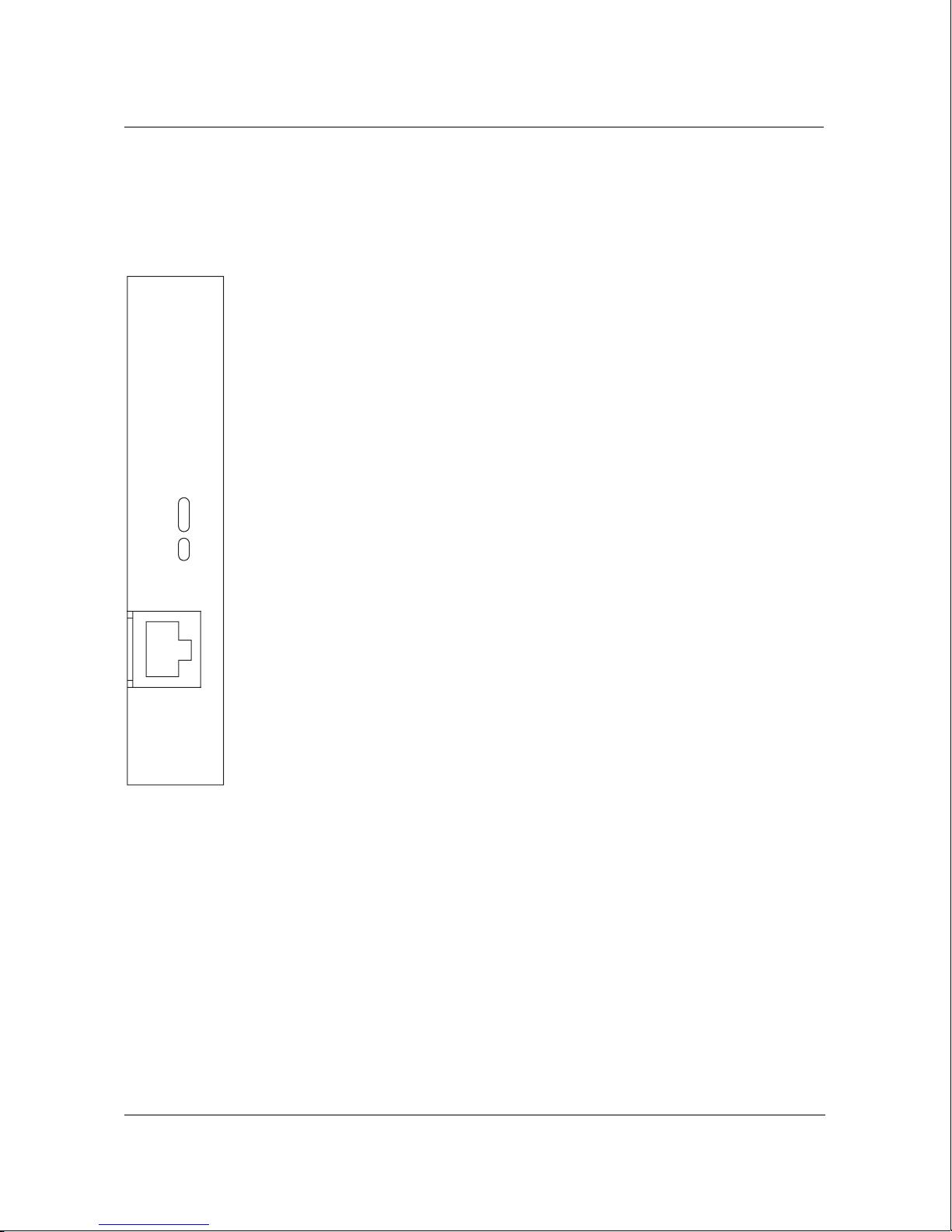
The port of the 100Base-TX P1 feature module has five indicator lamps,
labeled ERR, LINK, DPLX, DAT, and COL above the port connector.
ERR
The red ERR (error) indicator lamp always comes on when the WaveSwitch
100 is powered on. After the start-up self-tests are completed, the ERR
lamp normally goes off.
PTC217A
The ERR lamp stay s on if the electrical loopback test failed.
LINK
The green indicator lamp labeled LINK is normally on when the
WaveSwitch 100 is connected to a powered 100-Mbps Ethernet station.
The lamp stays on to indicate that the port is connected and ready for
operation.
ERR
LINK
DPLX
DAT
COL
If the station to which the WaveSwitch 100 is connected is powered off, the
lamp goes off.
DPLX
The yellow DPLX (duplex) indicator lamp stays on when the connection is
operating in full duplex mode. The lamp stays off when the connection is
operating in half duplex mode.
1
100BASE-TX
Other spe cifications
The mode of operation of 100Base-TX ports is set in the SWITCH.MIB
with the variable portFastEtherFullDuplexEnabled.
DAT
The yellow indicator lamp labeled DAT (data) comes on when the port is
receiving or transmitting data. Because the lamp responds to the flow of
data on the port, it normally comes on intermittently; however, if data traffic
on the port is heavy, the lamp can stay on for extended periods.
COL
The orange indicator lamp labeled COL (Collision) comes on when
outgoing (transmi tted) data and incoming (receive) data collide. The lamp
goes off when the collision has been resolved on the port.
See “General specifications” on page 45.
26 WaveSwitch 100 Ethernet Switch User Manual 12195
Page 49
Installing and monitoring a 100Base-FX P1 feature module
Installing and monitoring a 100Base-FX P1 feature module
The 100Base-FX P1 feature module is a one-port, high-speed DTE network
interface. Compliant with IEEE 802.3u, the 100Base-FX P1 feature module
transmits data at 100 Mbps in full-duplex mode up to 2000 meters
(6560 feet) over multimode fiber-opti c cable.
WaveSwitc h 100 Ethe rn et Swit ch12195User Manual
Tools and materials
You need the following tools to install an 100Base-FX P1 feature module:
• Phillips screwdriver (#2)
• 1/4-inch nutdriver (#4) or wrench
You need the following cabling to connect an 100Base-FX P1 feature
module to the network:
• dual 62.5/125 micron graded-index multimode fiber -opti c cable with
a dual SC connector (AMP 503553-1 or equivalent)
Installing a 100Base-FX P1 feature module
To install a 100Base-FX P1 feature module, use the procedure on page 21.
Connecting to the network
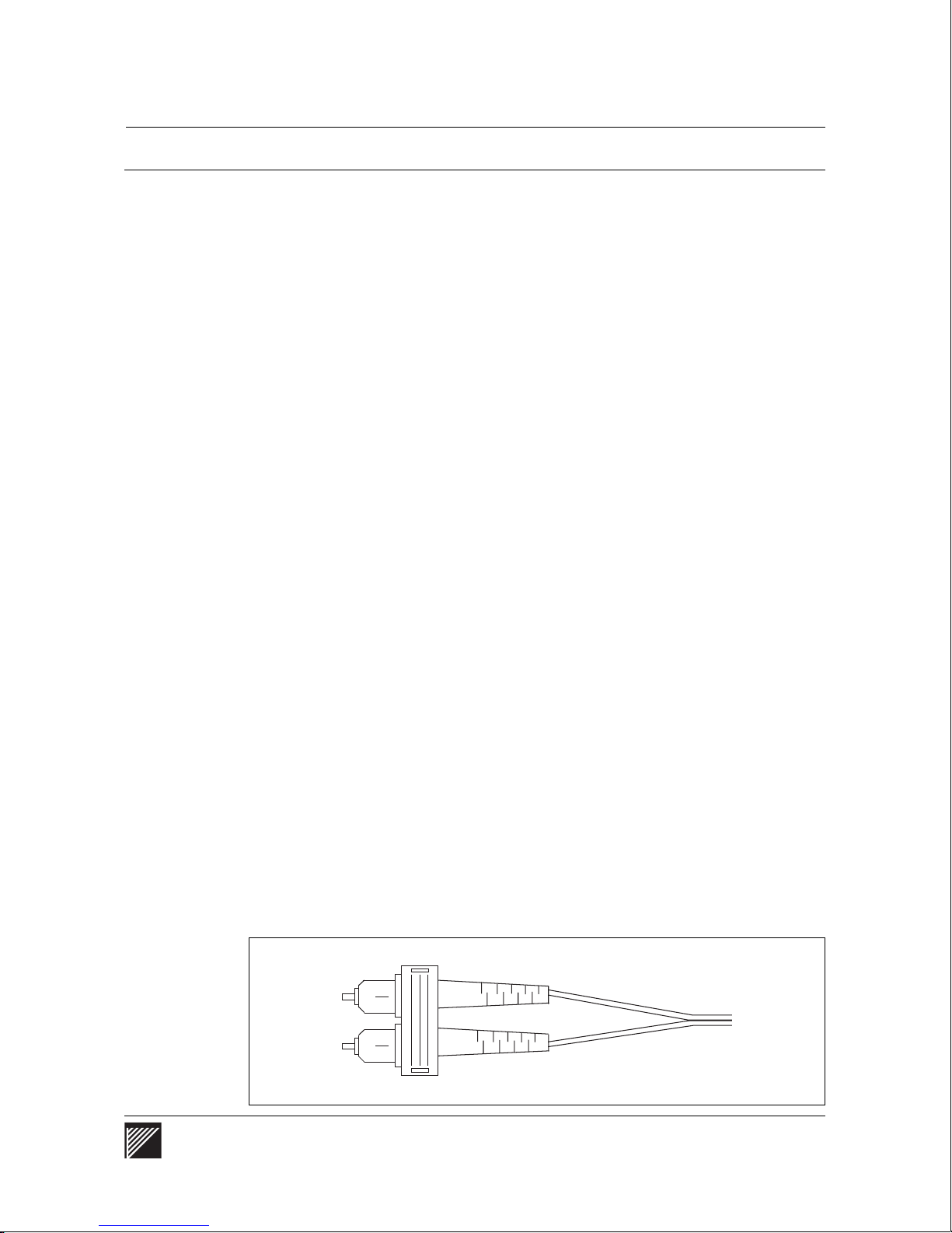
The 100Base-FX P1 port connects to the network through a dual
62.5/125 micron graded-index multim ode fiber- optic cable fit ted with a dual
SC connector (AMP 503553-1 or equivalent). The port needs two
connections: transmit and receive. These connections are made
simultaneously through the dual jack on the faceplate of the module.
See Figure 9.
Figure 9
Fiber-optic ca bl e with a dual SC connect or for use wi th the 100Base- FX P1 m odul e
WaveSwitch 100 Ethernet Switch User Manual 27
Page 50
Installing and monitoring a 100Base-FX P1 feature module
Monitoring the indicator lamps
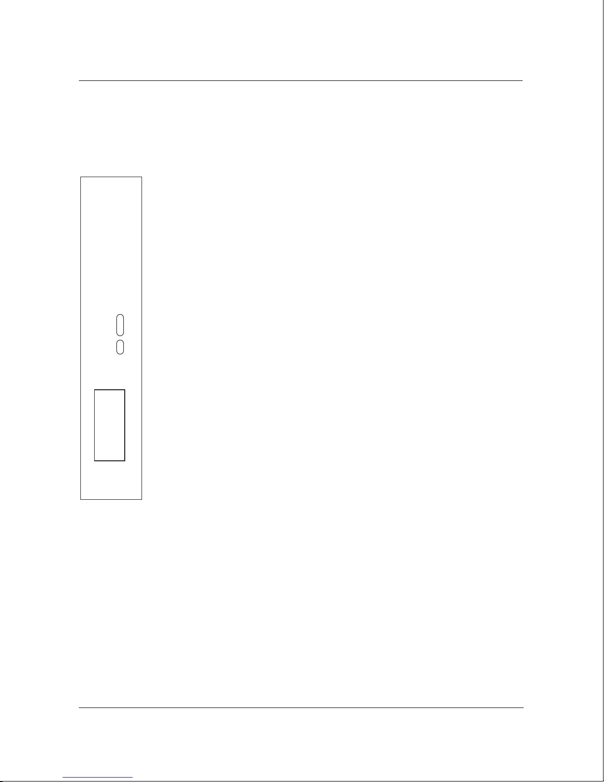
The port of the 100Base-FX P1 feature module has five indicator lamps,
labeled ERR, LINK, DPLX, DAT, and COL above the port connector.
ERR
The red ERR (error) indicator lamp always comes on when the WaveSwitch
100 is powered on. After the start-up self-tests are completed, the ERR
lamp normally goes off.
PTC217B
The ERR lamp stay s on if the electrical loopback test failed.
LINK
The green indicator lamp labeled LINK is normally on when the
WaveSwitch 100 is connected to a powered 100-Mbps Ethernet station.
The lamp stays on to indicate that the port is connected and ready for
operation.
ERR
LINK
DPLX
DAT
COL
If the station to which the WaveSwitch 100 is connected is powered off, the
lamp goes off.
DPLX
The yellow DPLX (duplex) indicator lamp stays on when the connection is
operating in full duplex mode. The lamp stays off when the connection is
operating in half duplex mode.
1
100BASE-FX
Other spe cifications
The mode of operation of 100Base-FX P1 ports is set in the SWITCH.MIB
with the variable portFastEtherFullDuplexEnabled.
DAT
The yellow indicator lamp labeled DAT (data) comes on when the port is
receiving or transmitting data. Because the lamp responds to the flow of
data on the port, it normally comes on intermittently; however, if data traffic
on the port is heavy, the lamp can stay on for extended periods.
COL
The orange indicator lamp labeled COL (Collision) comes on when
outgoing (transmi tted) data and incoming (receive) data collide. The lamp
goes off when the collision has been resolved on the port.
See “General specifications” on page 45.
28 WaveSwitch 100 Ethernet Switch User Manual 12195
Page 51

Installing and monitoring a 100Base-TX P4 feature module
Installing and monitoring a 100Base-TX P4 feature module
The 100Base-TX P4 feature module is a four-port repeater that provides
shared access to a high-speed network. Compliant with IEEE 802.3u, the
100Base-TX ports transmit data at 100 Mbps over 2-pair Category 5 UTP
(unshielded twisted pair) cable. You can use existing network and cable
infrastructures to connect links up to 100 meters (325 feet) between stations
or repeater/hubs.
WaveSwitc h 100 Ethe rn et Swit ch12195User Manual
Tools and materials
You need the following tools to install a 100Base-TX P4 module:
• Phillips screwdriver (#2)
• 1/4-inch nutdriver (#4) or wrench
To connect a 100Base-TX P4 feature module to the network, you need
Category 5 UTP cable with RJ-45 plugs at both ends
Installing a 100Base-TX P4 feature module
To install a 100Base-TX P4 feature module, use the procedure on page 21.
Connecting to the network
You need Category 5 UTP cable with RJ-45 plugs at both ends to connect
100Base-TX ports to the network.
The panel has four shielded RJ-45 jacks.
Connecting to a repeater/hub
To connect a 100Base-TX port on a WaveSwitch 100 to a 100Base-T
repeater/hub, use a crossover cable. The wiring scheme is described in
Table 1 on page 15.
Connecting to a network station
To connect a 100Base-TX port on a WaveSwitch 100 to a network station,
use a straight-through cable. The wiring scheme is described in Table 2 on
page 15.
If you do not have a straight-through cable, you can use an adapter cable
and a crossover cable in series to connect to a network station. See page 16.
WaveSwitch 100 Ethernet Switch User Manual 29
Page 52
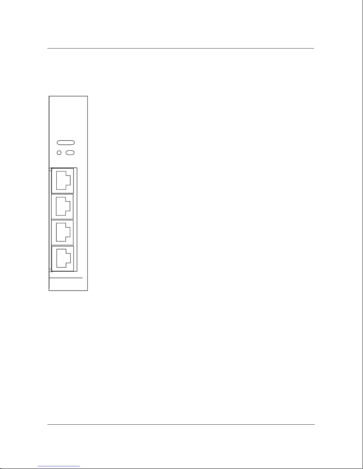
Installing and monitoring a 100Base-TX P4 feature module
Monitoring the indicator lamps
The 100Base-TX P4 repeater module has seven indicator lamps, labeled
1-4 (link), ERR, ACT, and COL.
1-4 (link)
The green link indicator lamps (1-4) are normally on when a port with the
PTC225A
corresponding number is connected to a powered 100-Mbps Ethernet
station. The lamp stays on to indicate that the port is connected and ready
for operation.
1234
ERR
ACT
COL
lamp goes off.
ERR
The red ERR (error) indicator lamp always comes on when the WaveSwitch
If the station to which the WaveSwitch 100 is connected is powered off, the
100 is powered on. After the start-up self-tests are completed, the ERR
4X
lamp normally goes off.
The ERR lamp stays on if a start-up test failed.
3X
ACT
The yellow ACT (activity) indicator lamp comes on when the port is
2X
receiving or transmitting data. Because the lamp responds to the flow of
data on the port, it normally comes on intermittently; however, if data traffic
on the port is heavy, the lamp can stay on for extended periods.
1X
COL
100BASE-TX
The yellow COL (collision) indicator lamp comes on when outgoing
(transmitted) data and incoming (receive) data collide. The lamp goes off
when the collision has been resolved on the port.
Other spe cifications
See “General specifications” on page 45.
30 WaveSwitch 100 Ethernet Switch User Manual 12195
Page 53
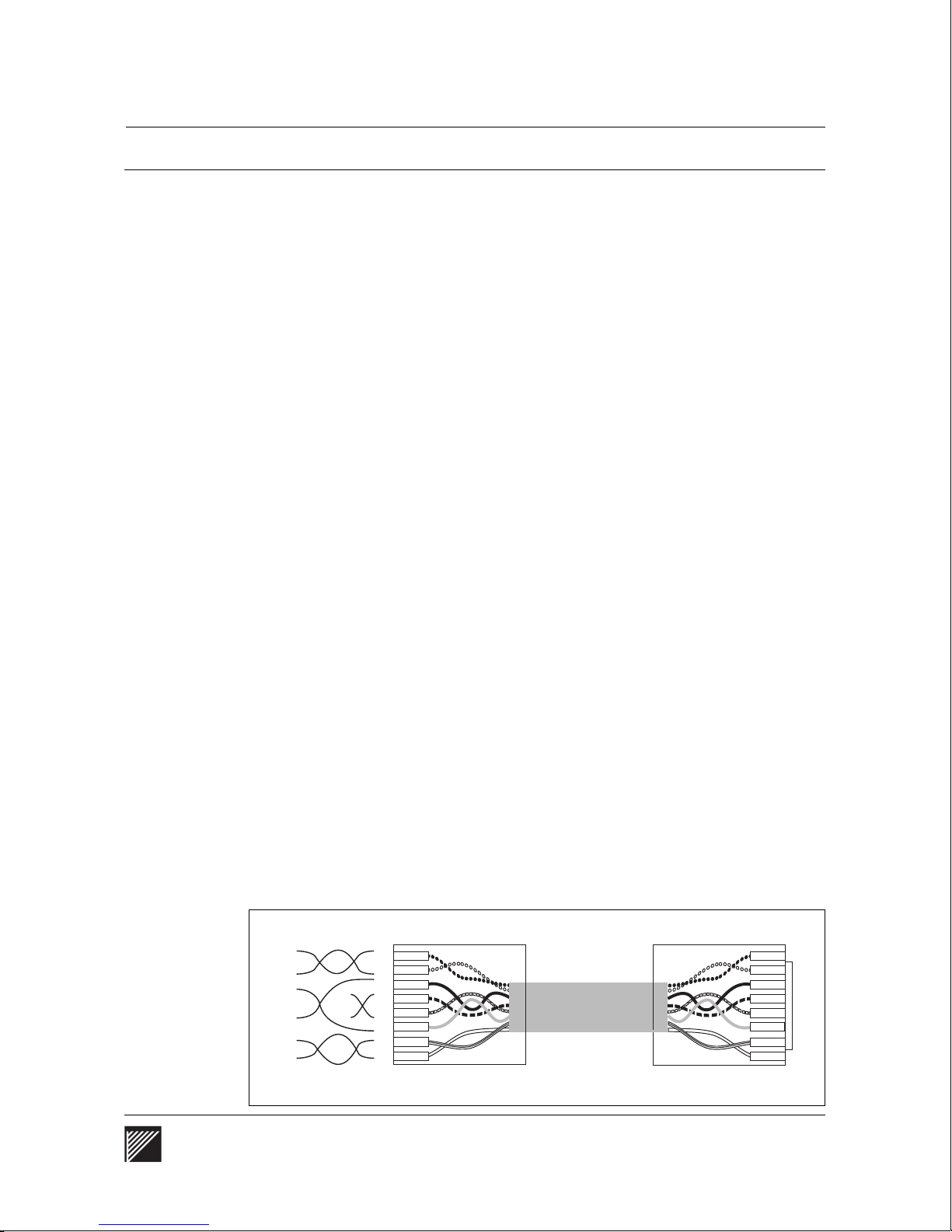
Installing and monitoring a 100VG-AnyLAN P5 feature module
Installing and monitoring a 100VG-AnyLAN P5 feature module
The 100VG-AnyLAN P5 feature module is a multiport repeater/hub with
one up port and four down ports. Compliant with the IEEE 802.12
specification, 100VG-AnyLAN technology tra nsmit s data at 100 Mbps over
4-pair, Category 3 (voice grade), Category 4, or Category 5 UTP
(unshielded twisted-pair) cable.
With 100VG-AnyLAN technology, you can use existing network and cable
infrastructures to connect UTP3 links up to 100 meters (325 feet) and
UTP5 links up to 200 meters (650 feet) between network devices.
WaveSwitc h 100 Ethe rn et Swit ch12195User Manual
Tools and materials
You need the following tools to install a 100VG-AnyLAN P5 module:
• Phillips screwdriver (#2)
• 1/4-inch nutdriver (#4) or wrench
You need the following cabling to connect a 100VG-AnyLAN P5 feature
module to the network:
• UTP straight-through cable with RJ-45 plugs at both ends; use
UTP3, UTP4, or UTP5 according to your requirements.
Install ing a 100VG-Any LAN P5 fea ture modu le
To install a 100VG-AnyLAN P5 feature module, use the procedure on
page 21.
Connecting to the network
The panel connectors are shielded RJ-45 jacks.
You can interconnect a 100VG-AnyLAN repeater/hub with other network
devices using UTP straight-through cable with RJ-45 plugs at both ends
(Figure 10).
Figure 10
Wiring schem e for 4-p air UTP straig ht- throu gh cabl e
Pair 1
Pair 2
Pair 4
Pair 3
1
2
3
4
5
6
7
8
WaveSwitch 100 Ethernet Switch User Manual 31
Page 54
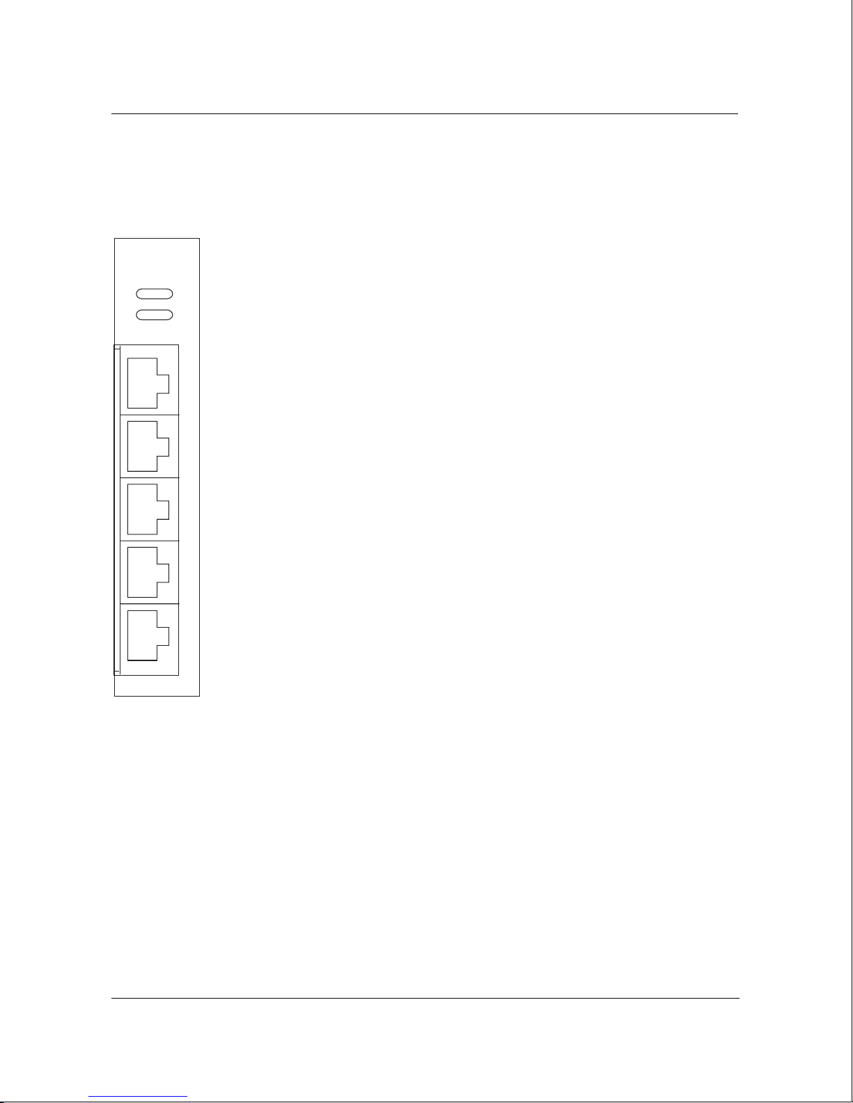
Installing and monitoring a 100VG-AnyLAN P5 feature module
Monitoring the indicator lamps
Each 100VG-AnyLAN P5 repeater/hub has eight indicator lamps, labeled
1-4, ERR, ACT, CAS, and UP above the port connectors.
1-4 (down ports)
The green down port indicator lamp normally comes on following the
start-up self-t est s and after link training is successfully completed; the lamp
PTC224A
1 2 3 4
UP
ACT
CAS
ERR
stays on when there is a connection between the port and the repeater/hub or
end station to which it is connected, and the connection is operating
properly.
The port lamp comes on for a short time and goes off before the module is
initialized.
U
ERR
The red ERR (error) indicator lamp always comes on when the WaveSwitch
4
100 is powered on. After the start-up self-te sts and link training are
completed, the ERROR lamp normally goes off.
The ERR indicator lamp stays on if a hardware error has been detected.
3
ACT
The yellow ACT (activity) indicator lamp goes on when the port transmits
2
or receives data.
CAS
1
The green CAS (cascade) indicator lamp normally comes on following the
start-up self-t est s and after link training is successfully completed; the lamp
stays on when there is a connection between a port on the module (up port
or down port) and another repeater/hub.
UP
The green UP (up port) indicator lamp normally comes on following the
start-up self-t est s and after link training is successfully completed; the lamp
stays on when there is a connection between the up port on the module and
the repeater/hub to which it is connected, and the connection is operating
properly.
Other spe cifications
See “General specifications” on page 45.
32 WaveSwitch 100 Ethernet Switch User Manual 12195
Page 55
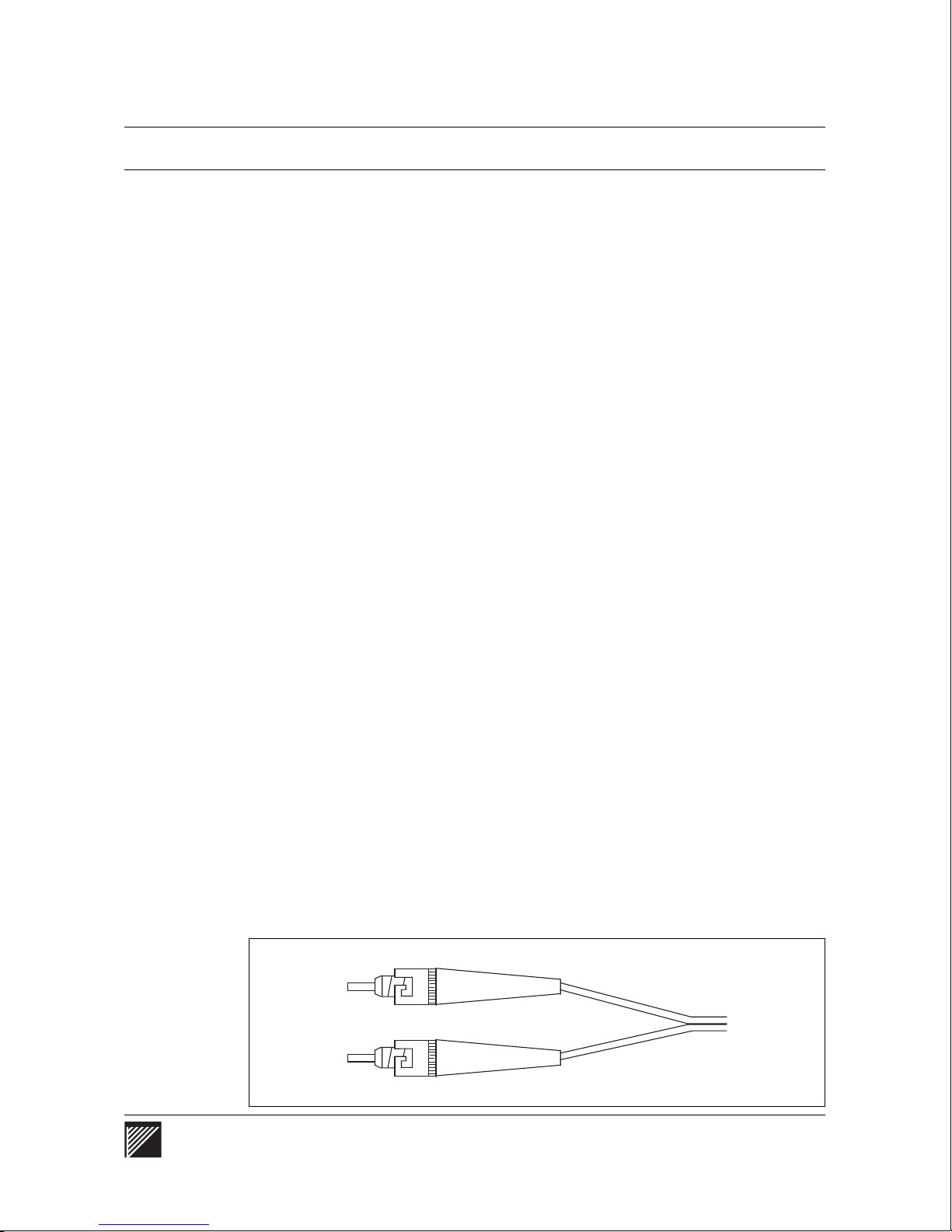
Installing and monitoring a WaveBus feature module
Installing and monitoring a WaveBus feature module
WaveBus is a 100-Mbps Fast Ethernet technology that uses fiber-optic
cable. In point-to-point connections, WaveBus operates full duplex to
provide a two-way bandwidth of 200 Mbps.
WaveBus feature modules are available with 820 nm or 1300 nm LED light
sources. An 820 nm WaveBus port connection can extend to 500 meters
(1640 feet); 1300 nm ports permit cable lengths up to 2000 meters
(6560 feet).
WaveSwitc h 100 Ethe rn et Swit ch12195User Manual
Tools and materials
You need the following tools to install a WaveBus module:
• Phillips screwdriver (#2)
• 1/4-inch nutdriver (#4) or wrench
You need the following cabling to connect each port of a WaveBus module
to the network:
• dual 62.5/125 micron graded-index multimode fiber -opti c cable with
ST-style connectors
Installing a WaveBus feature module
To install a WaveBus feature module, use the procedure on page 21.
Connecting to the network
Each WaveBus port needs two connections: transmit (TX) and
receive (RX). Make these connections using a dual fiber-optic cable fitted
with two ST-style connectors at each end. See Figure 11.
One-port WaveBus feature modules need one dual 62.5/125 micron
multimode fiber- optic cable to connect to the network. Two-port WaveBus
feature modules need two dual fiber-optic cables to connect to the network.
Figure 11
WaveBus connectors
WaveSwitch 100 Ethernet Switch User Manual 33
Page 56
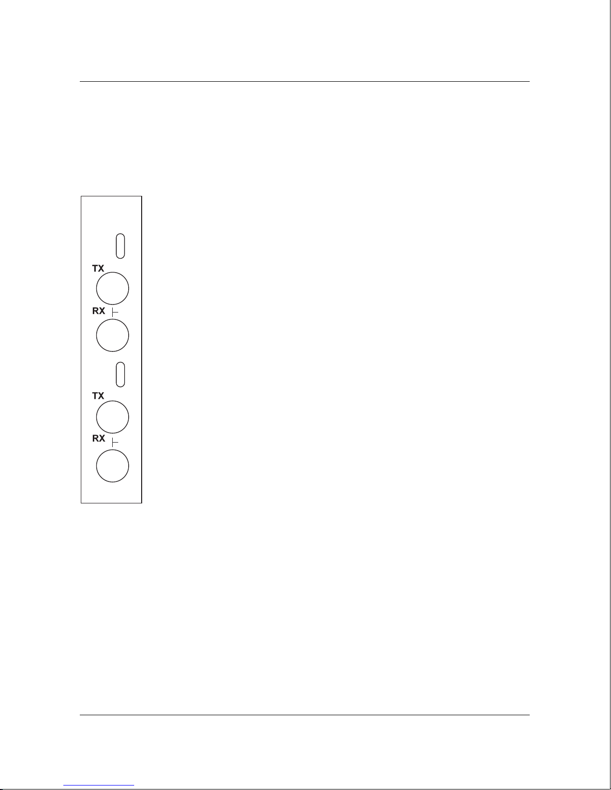
Installing and monitoring a WaveBus feature module
Monitoring the indicator lamps
Each one-port WaveBus feature module has three indicator lamps, labeled
CON, DAT, and ERR, above the TX and RX connectors. Each two-port
WaveBus feature module has two sets of indicator lamps and connectors;
the ports are labeled 1 and 2 on the faceplate of the module.
CON
The green CON (connect) indicator lamp normally comes on following the
start-up self-te sts; the lamp stays on when there is a logical connection
PTC216A
CON
DAT
ERR
between the port on the module and the equipment to which it is connected,
and the connection is operating properly.
The CON indicator lamp blinks continuously when the port is receiving
optical energy but no logical connection has been established.
DAT
2
The yellow DAT (data) indicator lamp goes on when the port receives data.
ERR
The red ERR (error) indicator lamp always comes on when the WaveSwitch
CON
DAT
ERR
100 is powered on. After the start-up self-tests are completed, the ERROR
lamp normally goes off.
The ERR indicator lamp stays on if a hardware error has been detected.
1
The ERR indicator lamp blinks if there is a connection error.
Note: When all three indicator lamps blink together, there is a
compatibility err or between the two ends of the connection. This means
1300nm
that the latest firmware or driver software needs to be installed.
TX
The TX (transmit) panel connector accepts 62.5/125 micron graded-index
multimode fiber- optic cable fit ted with an ST-style plug. The output power
of the transmitter is -15 dB m (minimum).
RX
The RX (receive) panel connector accepts 62.5/125 micron graded-index
multimode fiber- optic cable fit ted with an ST-style plug. The sensitivity of
the receiver is -25 dBm (maximum).
Other spe cifications
See “General specifications” on page 45.
34 WaveSwitch 100 Ethernet Switch User Manual 12195
Page 57

Installing and monitoring a 10Base-T P4 feature module
Installing and monitoring a 10Base-T P4 feature module
The 10Base-T P4 feature module is a four-port Ethernet interface.
Compliant with IEEE 802.3, the 10Base-T P4 feature module transmits data
at 10 Mbps over 2-pair Category 3 or Category 5 UTP (unshielded twisted
pair) cable. With a 10Base-T P4 feature module, you can use existing
network and cable infrastructures to connect links up to 100 meters
(325 feet) between stations or repeater/hubs.
WaveSwitc h 100 Ethe rn et Swit ch12195User Manual
Tools and materials
You need the following tools to install a 10Base-T P4 module:
• Phillips screwdriver (#2)
• 1/4-inch nutdriver (#4) or wrench
You need the following cabling to connect a 10Base-T P4 feature module to
the network:
• standard cables (Category 3 required, Category 5 recommended) to
connect ports to network stations (See Table 2 on page 15)
• crossover cables to connect ports to network equipment such as
repeater/hubs, routers, or bridges (See Table 1 on page 15)
Installing a 10Base-T P4 feature module
To install a 10Base-T P4 feature module, use the procedure on page 21.
Connecting to the network
The panel connectors are shielded RJ-45 jacks.
You can interconnect a 10Base-T P4 port with other 10-Mbps network
devices using Category 3 or Category 5 UTP cable with RJ-45 plugs at both
ends.
Connecting to a repeater/hub
To connect a 10Base-T P4 port on a WaveSwitch 100 to a 10Base-T
repeater/hub, use a crossover cable. The wiring scheme is described in
Table 1 on page 15.
Connecting to a network station
To connect a 10Base-T P4 port on a WaveSwitch 100 to a network station,
use a straight-through cable. The wiring scheme is described in Table 2 on
page 15.
If you do not have a straight-through cable, you can use an adapter cable
and a crossover cable in series to connect to a repeater/hub. See page 16.
WaveSwitch 100 Ethernet Switch User Manual 35
Page 58
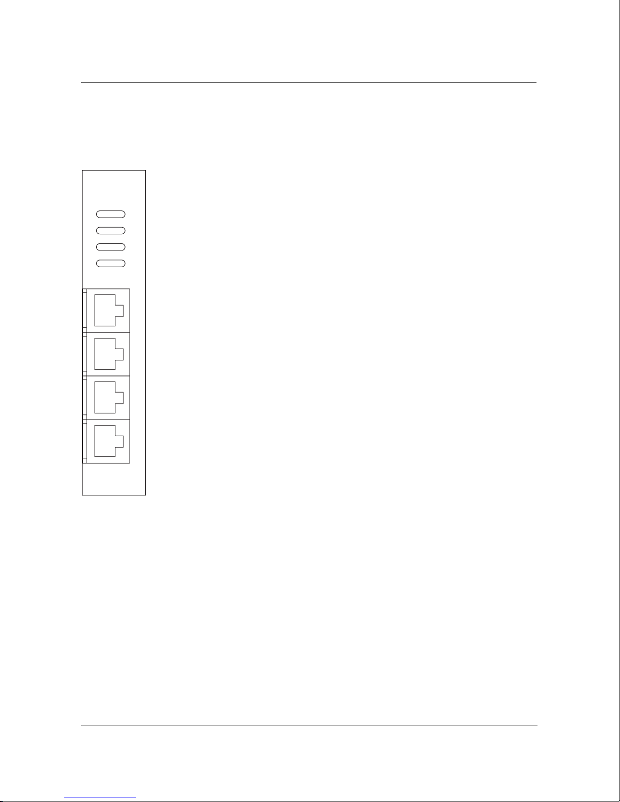
Installing and monitoring a 10Base-T P4 feature module
Monitoring the indicator lamps
There are four indicator lamps associated with each Ethernet port on the
10Base-T P4 feature module—ERROR, LINK, DATA, and COL.
ERROR
The red ERROR indicator lamp always comes on when the WaveSwitch
PTC221A
ERR
LNK
DAT
COL
4
3
2
1
100 is powered on. After the start-up self-tests are completed, the ERROR
lamp normally goes off.
The ERROR lamp stays on if the electrical loopback test failed.
If four adjacent ERROR indicator lamps come on and stay on, an error was
detected on the bridge-circuit ASIC that control s all four ports.
LINK
The green indicator lamp labeled LINK is normally on when the
4
WaveSwitch 100 is connected to a powered Ethernet station. The lamp
stays on to indicate that the port is connected and ready for operation.
3
If the station to which the WaveSwitch 100 is connected is powered off, the
lamp goes off.
2
DATA
The yellow indicator lamp labeled DATA comes on when the port is
receiving or transmitting data. Because the lamp responds to the flow of
1
data on the port, it normally comes on intermittently; however, if data traffic
on the port is heavy, the lamp can stay on for extended periods.
10BASE-T
COL
The orange indicator lamp labeled COL (Collision) comes on when
outgoing (transmi tted) data and incoming (receive) data collide. The lamp
goes off when the collision has been resolved on the port.
Other spe cifications
See “General specifications” on page 45.
36 WaveSwitch 100 Ethernet Switch User Manual 12195
Page 59

Replacing the power supply
Each WaveSwitch 100 base unit is shipped with the power supply installed.
If you need to replace the power supply, follow the steps below.
Step Action
1
Set the power switch of the WaveSwitch 100 to the off ( O ) position
and disconnect the power cord from the AC outlet.
2 Disconnect the power cord from its connector on the front of the
WaveSwitch 100.
3 Using a Phillips screwdriver (#2), turn the latch screw at the lower
front of the power supply counter-clockwise to release the unit.
4 Remove the power supply by sliding it out the front of the chassis.
CAUTION — Do not plug in the power supply when it is outside the
WaveSwitch 100 chassis. Doing so could cause personal injury or
damage to the power supply, or both.
Replacing the power supply
WaveSwitc h 100 Ethe rn et Swit ch12195User Manual
5 Prepare the latch on the replacement power supply for installation
by turning the latch screw counter-clockwise at least three full turns.
6 Slide the replacement power supply into the chassis from the front
and engage the connector with minimum force.
7 Turn the latch screw clockwise until it resists further movement . Do
not overtighten the latch screw.
8 Make sure the power switch on the WaveSwitch 100 is in the
off (
O ) position. Attach the power cord to the connector on the
front of the power supply.
9 Connect the other end of the power cord to the AC supply source
and set the power switch to the on (
end
I ) position.
WaveSwitch 100 Ethernet Switch User Manual 37
Page 60
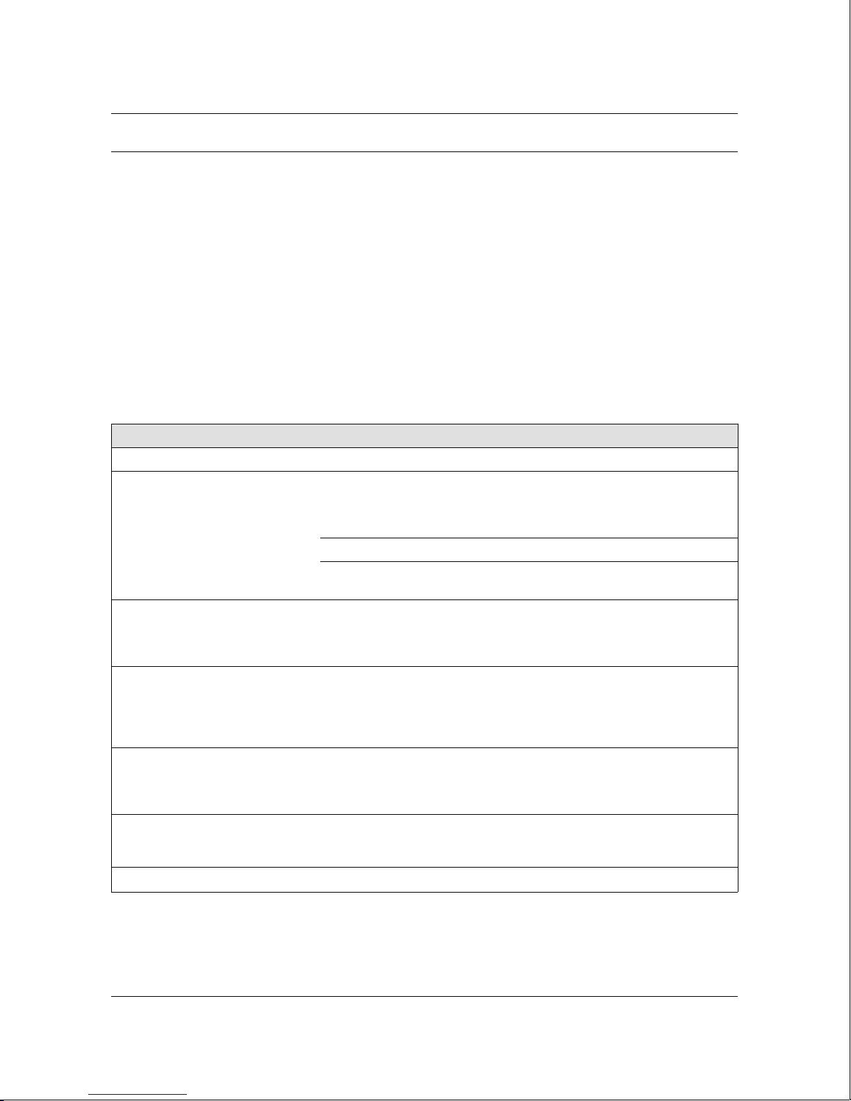
Troubleshooting guide
Troubleshooting guide
The following table gives information to help you determine and correct
conditions that can be displayed by the indicator lamps on the front panel of
the WaveSwitch 100.
Possible conditions are listed under these headings:
• General status
• Ethernet ports
• FDDI ports
• 100Base-TX ports
• 100VG-AnyLAN ports
• WaveBus ports
12195User ManualWaveSwitc h 100 Ethe rn et Swit ch12195User Manual
Condition Possible cause Corrective action
Gene ra l st at us
The system PO WER in dicat or
lamp does not come on wh en t h e
power switch is set to the on ( I )
position
The system ERROR indicator
lamp stays on af ter the st ar t-up
self-tests are completed
The system ERROR indicator
lamp blinks steadily after the
start-up self -test s are com plet ed
indicat ing th at the unit is re ady for
new software to be loaded
The system ERROR indicator
lamp blinks a three-group
flashcode after the start-up
self-tests are complete d
SYSTEM LOAD FPS indicator
lamps do not come on
AC power cord is not con nect ed Connect the po wer co rd
AC power sourc e is not operat io nal C h eck the AC powe r source
The power supply in the unit is
faulty
A hardware error was detected on
the motherboard during the
start-u p self-t est s
The softwar e, whic h is loaded in
ROM at the factory , is corrupt e d
A start-up self- test has failed Note the three- group f lash co de
There is no dat a traff ic on t he
WaveSwitch 100
end
Replace the po wer supply
Power off the unit and power it on
again; if the lam p stays on cal l
Plaintree System s Technica l
Support for instructions
Load new sof twa re using the
update disket te provid ed, or call
Plaintree System s Technica l
Support for instructions
and call Plaintree Systems
Technical Support for in structions
Make sure the application or
equipment connect e d to the unit is
operat in g cor rec tly
38 WaveSwitch 100 Ethernet Switch User Manual 12195
Page 61
Troubleshooting guide
Condition Possible cause Corrective action
Ethernet ports
ERROR indicator lamp above an
Ethernet port conn ector stays on
ERROR indicator lamps above
four adjacent Ethernet port
connectors of one group stay on.
For the 16-po rt unit, the po rt
groups are: 1-4, 5-8, 9-12, and
13-16.
LINK indicator lamp above an
Etherne t po rt connector goes off
Electrical loopback test failed Power off the unit and power it on
again; if this does not correct the
fault, conn ect to a spare port, if
one is available, to continue
operatio n and call Plaintree
Systems Technical Support for
instructions
Group error was detected during
the electrical loopb ack t est for four
ports that are common to one
bridge-cir cuit ASIC on th e
motherboard
Cable connection is bro ken Make sure connector s are seat ed
Network station to which the po rt is
connected has been po were d off
Wrong type of cable is conne cted
between the po rt and th e
equipment
Connect to spare ports, if
available, to continue operation
and call Plaintree Systems
Technical Support for in structions.
correctly in the equipmen t at both
ends of the cab le
Check the co ntin uity of the wires in
the cable and the pin assignments
on the RJ-45 connector s
Make sure the station to which th e
port is connected is plugged in and
powered on
Make sure th e right type of cable is
connected to the port— a
straight-th rou gh cab le for a
network station connection, or a
crossove r cable for a repeat er /hub
connection
DATA indicat or lamp above an
Ethernet port neve r
comes on or never blinks
The orange COL indicator lamp
above an Ethernet port comes on
frequently or stays on for long
periods of time
Cable connect ion is bro ken or
faulty
Equipment to whic h the port is
connected is not oper at ing
The LAN is congested and
collisions between transm it ted and
received data are taking place at a
high rate
end
WaveSwitch 100 Ethernet Switch User Manual 39
Make sure the LIN K indicator lamp
is on; if the LINK indicator lamp is
off, take the corrective actions
listed above.
Make sure the equipment to which
the port is connected is ope rat ing
properly
Redistribut e the load on the LAN;
locate and move the devices that
are overloading the LAN to
another port or LAN segmen t
Page 62

Troubleshooting guide
Condition Possible cause Corrective action
FDDI ports
The red ERROR indicator lamp
above an FDDI port connector
stays on
The green RG OP indicat or lamp
on the FDDI feature module blinks
steadily, indicating that the FDDI
module is isolated from the FDDI
ring
The WRP A indicator lamp comes
on and stays on, and the RG OP
lamp st a y s on; this mea ns t he r e is
no signal on the B port of the DAS
FDDI featur e module.
Electrical loopback test failed due
to a hardware fault
The start-up self-tests are not yet
completed af ter the un it has been
powered on
The cables are not connected at
one end, or the cable connec tors
are not seated pr oper ly in the
housings
Faulty cable. Both le ads are
broken.
Faulty cable. The two cab le leads
are reversed in the keyed
connectors at both ends of the
cable.
The equipment to which the B port
is connected is not oper at ion al
Power off the unit and power it on
again; if this does not correct the
fault, conn ect to a spare port, if
one is available, to continue
operatio n and call Plaintree
Systems Technical Support for
instructions
This is normal during t he star t-up
self-tests. The RG O P la mp blinks
until a traffic-r ead y connect ion i s
established; the lamp stays on
when the con nect ion to the FDDI
ring is operational.
Make sure the cables are
connected t o equipmen t at both
ends, and tha t the connec to rs are
seated prope rly in th e hous ings of
the equipment
Test th e cable; repair or rep la ce
the cable.
Test th e cable; repair or rep la ce
the cable.
Locate the n o n-o per at io nal
equipment connect e d to the B port
and power it on, or correct the
condition, or replace the equipment
The WRP B indicator lamp comes
on and stays on, and the RG OP
lamp st a y s on; this mea ns t he r e is
no signal on the A port of the DAS
The connect ing ca ble to the B port
is broken
The equipment to which the A port
is connected is not oper at ion al
Test or replace the cable
connected to the B port
Locate the n o n-o per at io nal
equipment connect e d to the A port
and power it on, or correct the
condition, or replace the equipment
FDDI featur e module.
All the indicator lamps on the
feature module are off and the
indicat or lamps on the base unit
The connect ing ca ble to the A port
is broken
The featur e mo dule is not
receiving power
Test or replace the cable
connected to the A port
Make sure th e feat ure module is
seated co rrect ly in its slot
connector in the bas e unit
are working normally
end
WaveSwitc h 100 Ethe rn et Swit ch12195User Manual
40 WaveSwitch 100 Ethernet Switch User Manual 12195
Page 63

Troubleshooting guide
Condition Possible cause Corrective action
100Base-TX po rts
ERR indicator lamp above the port
connector stays on
LINK indicator lamp above th e port
connector goes off
Electrical loopback test failed Power off the unit and power it on
again; if this does not correct the
fault, conn ect to a spare port, if
one is available, to continue
operatio n and call Plaintree
Systems Technical Support for
instructions
Cable connection is bro ken Make sure connector s are seat ed
correctly in the equipmen t at both
ends of the cab le
Check the co ntin uity of the wires in
the cable and the pin assignments
on the RJ-45 connector s
Network station to which the po rt is
connected has been po were d off
Make sure the station to which th e
port is connected is plugged in and
powered on
Wrong type of cable is conne cted
between the po rt and th e
equipment
Make sure th e right type of cable is
connected to the port:
–for a one-port feature modul e:
crossover cable to repeate r/hub s
and straight -through cable to
network stations
–for a fou r- p or t fe at u re m o dule:
crossover cable to network
stations and straight -thr oug h cable
to repeater/hubs
The DPLX (duplex) indicat or lamp
stays off
DATA indicat or lamp above the
port never come s on or never
blinks
The orange COL indicator lamp
above the port comes on
frequently or stays on for long
periods of time
All the indicator lamps on the
feature module are off and the
indicat or lamps on the base unit
are working normally
WaveSwitc h 100 Ethe rn et Swit ch12195User Manual
Operation of the port is not set to
full duplex mode
Cable connect ion is bro ken or
faulty
Equipment to whic h the port is
connected is not oper at ing
The LAN is congested and
collisions between transm it ted and
received data are taking place at a
high rate
The featur e mo dule is not
receiving power
end
Change the setting of the variable
portFastEtherFu llDuplexEnabled
the SWITCH.MIB.
Make sure the LIN K indicator lamp
is on; if the LINK indicator lamp is
off, take the corrective actions
listed above.
Make sure the equipment to which
the port is connected is ope rat ing
properly
Redistribut e the load on the LAN;
locate and move the devices that
are overloading the LAN to
another port or LAN segmen t
Make sure th e feat ure module is
seated co rrect ly in its slot
connector in the bas e unit
in
WaveSwitch 100 Ethernet Switch User Manual 41
Page 64
Troubleshooting guide
Condition Possible cause Corrective action
100VG-AnyLAN por ts
The red ERR indicator lamp on the
100VG-AnyLAN m odule stays on
All the indicator lamps on the
100VG-AnyLAN feat ure module
are off and the indicator lamps on
the base unit ar e work ing nor ma lly
WaveSwitc h 100 Ethe rn et Swit ch12195User Manual
Electrical loopback test failed due
to a hardware fault
Power off the unit and power it on
again; if this does not correct the
fault, conn ect to a spare port, if
one is available, to continue
operatio n and call Plaintree
Systems Technical Support for
instructions
Link training failed Make sure the module is
connected to a 100VG-AnyL A N
hub; make sure the cable is a
four-pair ca ble; make sur e the
cable is not faulty .
The featur e mo dule is not
receiving power
Make sure th e feat ure module is
seated correctly in the connector in
the base unit
end
42 WaveSwitch 100 Ethernet Switch User Manual 12195
Page 65
Troubleshooting guide
Condition Possible cause Corrective action
WaveBus ports
The red ERROR indicator lamp
above a port connector on the
WaveBus modu le stays on
The green CO N and red ERR
lamps on the WaveBus module
both blink continuo usly indicat ing
an illegal connection
All the indicator lamps on the
WaveBus modu le are off and the
indicat or lamps on the base unit
are working normally
WaveSwitc h 100 Ethe rn et Swit ch12195User Manual
Electrical loopback test failed due
to a hardware fault
The module is connect e d to an UP
port on a repeater/hub
RX and TX cable leads are
crossed be twe en t he WaveBu s
module and the eq uipm ent to
which it is connected
The featur e mo dule is not
receiving power
end
Power off the unit and power it on
again; if this does not correct the
fault, conn ect to a spare port, if
one is available, to continue
operatio n and call Plaintree
Systems Technical Support for
instructions
Connect to the module t o a DOW N
port on t he repeate r/h ub
Reverse the cable leads on the
WaveBus modu le or on the
equipment to which it is connect ed
Make sure th e feat ure module is
seated co rrect ly in its slot
connector in the bas e unit
WaveSwitch 100 Ethernet Switch User Manual 43
Page 66

Getting technical assistance
Getting technical assistance
You can get assistance with installing and troubleshooting a WaveSwitch
100 Ethernet Switch by calling the technical support staff. See page iii.
Be prepared to supply the following information when you call:
• description of the problem
• description of the steps you have taken to try to correct the problem
• status of the front-panel indicator lamps
• model number of the unit
• software version in use (see page 58)
• configuration of the unit
• version of the network management system in use
• configuration of your network
WaveSwitc h 100 Ethe rn et Swit ch12195User Manual
44 WaveSwitch 100 Ethernet Switch User Manual 12195
Page 67

General specifications
Dimensions
• Width: 43.9 centimeters (17.25 inches)
• Height: 13.3 centimeters (5.20 inches) (3U)
• Depth: 43.9 centimeters (17.25 inches)
Weight
• 12.3 kilograms (27 pounds)
Mounting op tion s
• Rack mounting:
– 19-inch EIA RS-310C rack
– IEC Pub 297 rack
• Freestanding
Power input specifications
The power unit has universal voltage ratings; it selects its mode of operation
automatically provided the supply ratings at your site are within the
following specificatio ns:
General specifications
• Voltage range:
– 90 to 132 VAC
– 180 to 264 VAC
• Frequency range: 47 to 63 Hz
• Maximum current ratings:
– 5 A at 115 VAC
– 2.5 A at 230 VAC
Environmental specifications
• Temperature
– Operating: 0°C to 50°C (32°F to 122°F)
– Storage: -40°C to +85°C (-40°F to +185°F)
• Relative humidity (non-condensing)
– Operating: 10% to 80%
– Storage: 5% to 95%
• Operating access requirements
– Front: 60 centimeters (24 inches) minimum for power unit
replacement
– Rear: 10 centimeters (4 inches) minimum for cooling air
exhaust
WaveSwitch 100 Ethernet Switch User Manual 45
Page 68

Page 69

Managing a Wave Switch 100 Ethernet Switch
This chapter describes how to use the console services to monitor and
manage a WaveSwitch 100 Ethernet Switch.
This chapter contains the following sections:
• About the console 48
• Setting up and starting the local console 49
• Console command-line commands 51
• Error messages for the GET, SET, and GETNEXT commands 56
• Console window commands 57
• Console menu commands 63
• Port address formats 66
• About SNMP 68
• SNMP and the WaveSwitch 100 Ethernet Switch 69
• About configuration information 70
• Datafilling the configur ation fiel d s 73
• Configuration procedures 76
• Configuring a WaveSwitch 100 Ethernet Switch locally 77
• Configuring a WaveSwitch 100 Ethernet Switch remot ely 79
• Reloading configuration infor mation 85
• Configuring the spanning tree 86
• Configuring a traffi c analyzer port 87
• Using the static filter database 88
• Updating the firmware using TFTP 90
WaveSwitc h 100 Ethe rn et Swit ch12195User Manual
WaveSwitch 100 Ethernet Switch User Manual 47
Page 70

About the console
About the console
The console lets you
• view online help
• view system data
• view external port data
• view internal port data
• configure the WaveSwitch 100 Ethernet Switch
• manage the WaveSwitch 100 Ethernet Switch
Figure 12 shows the names of the commands, windows, and menu items
that you can use during a console session.
You can gain access to the console
• locally by connecting a terminal to the WaveSwitch 100 Ethernet
Switch
• remotely by establishing a Telnet connection from a network station
Note: You can run one local console session and up to four remote
console (Telnet) sessions at a time. No more than 10 Telnet sessions
can be activated within a four-minute period.
Figure 12
Console commands , windows, and menu ite ms
Command-line commands
_HELP
_SYSMAN
_MIBLIST
_GET
_GETNEXT
_SET
_CHANGEPW
_ENABLEPW
_DISABLEPW
_WHERETO
_TAP
_EXIT
Window invoked by the
Configure Management menu item
Windows invoked
by function keys
Commands in
the menu of the
System Commands
window
Window invoked by the
Frame Loss Incident Report menu item
_System Data (F1)
_External Port Data (F2)
_Internal Port Data (F3)
_System Commands (F4)
_Reset Counters
_Erase Non-Volatile Store
_Turn On Aging/Turn Off Aging
_Configure Management
_Display Address Canonically/Non-canonically
_Frame Loss Incident Report
FLI Report
Management Configuration
(default window)
48 WaveSwitch 100 Ethernet Switch User Manual 12195
Page 71

Setting up and starting the local console
System requirements
Hardware requirements
• WaveSwitch 100 Ethernet Switch
• one of the following:
– a VT100 terminal
– a VT100 terminal emulator running on a workstation or
personal computer (PC)
• a straight-through RS232 cable with a 9-pin male D-subminiatur e
connector on one end and an appropriate connector on the other end
to attach to the VT100 terminal or VT100 terminal emulator
Software requi remen ts
If you are using a workstation, use the VT100 terminal emulation software
appropriate for your workstation.
If you are using a PC to emulate a VT100 terminal, you can use the
following software:
Setting up and starting the local console
• in a DOS environment:
– MS-DOS 3.30 or later
– PROCOMM PLUS for DOS
• in a Windows environment:
– Microsoft Windows 3.1 or later
– Windows Terminal or PROCOMM PLUS for Windows
Note: Because of their compatibility and reliability, the software
combinations listed above are recommended. Other applications may
also provide satisfactory results.
VT100 terminal settings
Use the following modem settings when connecting the VT100 terminal or
VT100 terminal emulator to the WaveSwitch 100:
• transmit and receive speed: 9600 or 19200 baud
• no parity
• 8 data bits
• 1 stop bit
• XON/XOFF flow control
• line wrap: OFF
WaveSwitch 100 Ethernet Switch User Manual 49
Page 72

Setting up and starting the local console
Starting the local console
To start the local console, do the steps below.
Step Action
1
Connect a VT100 terminal or a VT100 terminal emulator to the
PC/MODEM port on the WaveSwitch 100 using a straight-through
RS232 cable.
2 Make sure both units are powered on.
3 Press RETURN.
When the command line appears, you can enter the console commands
shown in Figure 12 on page 48.
Press the up-arrow key to recall the last command line you entered. Press
the down-arrow key to go to the next line.
Press CTRL-X to clear the line.
end
Note: The next section gives the definitions and syntax for the
command-line commands. Use the online HELP for more information
about parameters you can use with the commands and to see examples
of queries using the commands.
50 WaveSwitch 100 Ethernet Switch User Manual 12195
Page 73

Console command-line commands
HELP
HELP invokes the online facility that describes and gives examples of the
commands and command parameters (topics) that you can use from the
command line of the console.
To see a list of topics for which online help is available, enter
HELP
To view the online help for a specific topic, enter
HELP [topic]
SYSMAN
SYSMAN invokes the full-screen system manager windows. You can use
the system manager windows to view information about the system, to view
real-time port statistics, to enter system commands, and to enter system
configuration data.
To invoke the system manager windows, enter
SYSMAN
Console command-line commands
The default window, System Data, appears from which you can invoke
other system manager windows using the function keys specified on the
prompt bar at the bottom of the window.
MIBLIST
MIBLIST displays all MIB object class names that start with a specified
search string. If the search string is not specified, all MIB object class names
are displayed.
To view a MIBLIST for a specified search string, enter
GET
GET retrieves a specified MIB object. If you enter only part of the name of
a MIB object (for example, dot1db), a pop-up window containing up to
16 entries in two columns appears. Use the arrow keys to highlight an
object name, and press RETURN to select the object. The system displays
the result on the next line. Press CTRL-X to exit the pop-up window.
If a MIB object is not specified, the GET operation acts on the object
referenced by the last successful GET, SET, or GETNEXT operation.
MIBLIST [search_string]
WaveSwitch 100 Ethernet Switch User Manual 51
Page 74

Console command-line commands
To retrieve the value of a specified MIB object, enter
GET [mib_object]
If the MIB object is part of a table, you must add information (separated
from the object name by a period) to distinguish it from other instances.
For example,
Get [mib_object.port_number]
Get [mib_object.port_number.index_number]
Note: For additional instructions on retrieving MIB objects, see the first
page of individual MIB sections, listed on page 113.
For a list of error messages associated with this command, see page 56.
GETNEXT
GETNEXT displays the value of the next MIB object in the MIB.
If a MIB object is not specified, the value of the object following the object
referenced by the last successful GET, GETNEXT, or SET operation is
displayed.
SET
To retrieve the value of the next MIB object, enter
GETNEXT [mib_object]
For a list of error messages associated with this command, see page 56.
SET changes the value of a specified MIB object to a specified value.
If the SET is successful, a GET is done automatically so you can verify the
change.
The value you specify can be an integer (specify hexadecimal numbers by
prefixing them with 0x), a text string, or an octet string (which is a sequence
of hexadecimal bytes separated by blanks).
To set a MIB object, enter
SET [mib_object] [value]
If the MIB object is part of a table, you must add information (separated
from the object name by a period) to distinguish it from other instances.
52 WaveSwitch 100 Ethernet Switch User Manual 12195
Page 75

For example,
Set [mib_object.port_number] [value]
Set [mib_object.port_number.index_number] [value]
For additional instructions on setting MIB objects, see the first page of
individual MIB sections, listed on page 113.
For a list of error messages associated with this command, see page 56.
CHANGEPW
CHANGEPW changes the password; there is only one password, which is
shared between the local and remote console.
When you invoke CHANGEPW from the local console, the system prompts
you for a new password.
When you invoke CHANGEPW from the remote console, the system
prompts you for the current password. You must enter the current password
correctly before you are allowed to change the password.
Console command-line commands
The default password is default.password
To change the password, enter
CHANGEPW
The console password
• must be made up of two character strings that contain alphabetic or
numeric characters only
• must have one non-alphabetic or non-numeric character separating
the two character strings
• must not contain blank spaces
• must not be longer than 40 characters
ENABLEPW
ENABLEPW enables the password for the local and remote console.
When the password is enabled, users must specify the correct password
before they can gain access to console services. The default values are local
password DISABLED and remote password ENABLED.
To enable the local console password, enter
ENABLEPW L
WaveSwitch 100 Ethernet Switch User Manual 53
Page 76

Console command-line commands
To enable the remote console password, enter
ENABLEPW R
Note: The ENABLEPW command is accessible only from the local
console.
DISABLEPW
DISABLEPW disables the password for the local and remote console.
When the password is disabled, users must specify the correct password
before they can gain access to console services. The default values are local
password DISABLED and remote password ENABLED.
To disable the local console password, enter
DISABLEPW L
To disable the remote console password, enter
DISABLEPW R
WHERETO
WHERETO displays the port numbers to which frames destined to a
specified MAC address are forwarded.
To display the port numbers to which frames are forwarded, enter
Use spaces or hyphens between bytes of the Mac address to indicate
canonical format. See “Port address formats” on page 66.
TAP
TAP specifies a port, designated by the port number, to be the traffic
analyzer port (TAP). The TAP transmits all frames that were received
(accepted for forwarding) from all other port s.
Specifying a port number of 0 (zero) disables the TAP.
To specify a port as the TAP, enter
Note: The DISABLEPW command is accessible only from the local
console.
WHERETO [MAC address]
TAP [port_number]
54 WaveSwitch 100 Ethernet Switch User Manual 12195
Page 77

EXIT
Console command-line commands
If a port number is not specified, the current setting of the TAP is displayed
on the console.
When the unit is powered on for the first time, the TAP is disabled (0); any
change in the setting is preserved across restarts.
For more information about the TAP, see page 87.
EXIT closes a telnet session.
To close a telnet session, enter
EXIT
Note: The EXIT command works only in a telnet session.
WaveSwitch 100 Ethernet Switch User Manual 55
Page 78

Error messages for GET, SET, and GETNEXT commands
Error messages for GET, SET, and GETNEXT commands
The following table gives the meanings of the error messages that can be
displayed when you are retrieving or setting MIB objects using the GET,
SET, and GETNEXT commands.
Error message Meaning
Error in object name The specified MIB object does not
exist in the MIB. Check instance.
Error in value The specified value is not valid for the
specified MIB object.
Missing parameter The set function requires both a
MIB object and a value.
No previous object name There is no MIB object specified for a
GET or GETNEXT command an d
there is no previous reference to a
MIB object.
Object read-only The value of the MIB object cannot
be modified.
Object irretrievable The MIB object has more than one
instance, which requires more
specific command information to
retrieve or modify it, or the specified
MIB object does not exist in the MIB.
Value out of bounds The value is out of the range of valid
values for the MIB object you
specified.
Value syntax error The specified value is not in the
correct format. For example, you
entered a string where an integer was
required.
56 WaveSwitch 100 Ethernet Switch User Manual 12195
Page 79

Console window commands
When you enter the command SYSMAN on the command line, the
System Data window appears. See Figure 13.
The banner at the top of the window displays the program name and the
Up Time. The Up Time field displays the elapsed time since the
WaveSwitch 100 was powered on.
The prompt bar at the bottom of the window shows the function keys you
can press to view other windows.
The windows show:
• system data (F1-System)
• external port data (F2-E port Stat s)
• internal port data (F3-Iport Stats)
• system commands (F4-Commands)
To exit a window, press CTRL-X. The window closes and the cursor
appears on the command line of the console.
Console window commands
To restart the windows from the command line, type SYSMAN and press
RETURN.
Figure 13
The System Data window of the System Mana ger (SYSMAN)
Up Time: 0:00:04:55_ WaveSwitch 100 Ethernet Switch System Manager
System Data
Slot: FIXED SLOT 1 SLOT 2
Product Code: PTP110A PTC217A PTC225A
Date Of Manufacture: 29/07/94 08/11/95 09/11/95
Serial Number: 00005289 00006821 00006829
Base MAC Address: 0040EA-0127D8 0040EA-10054E 0040EA-10058E
Software Version: 3.23
Bootprom Version: 1.5
IP Address: 0.0.0.0 Gateway: 0.0.0.0
Subnet Mask: 255.0.0.0 Filter Database Aging: Off
Name: Uninitialized
Location: Uninitialized
Contact: Uninitialized
F1-System F2-Eport Stats F3-Iport Stats F4-Commands Ctrl-X: Exit
WaveSwitch 100 Ethernet Switch User Manual 57
Page 80

Console window commands
System Data window (System)
The System Data window appears when you run the SYSMAN command
from the command line of the console. See Figure 13 on page 57.
You can access this window from any other window by pressing F1.
The System Data window contains information about the system
motherboard, called the Management Feature Module (MFM), and the
feature modules installed in each option slot. If no modules are installed in
an option slot, the entrie s for the slot are blank.
The system data for each module is contained in two groups of fields. The
first group consists of the following fields:
• Product Code
• Date of Manufacture
• Serial Number
• Base MAC Address (assigned to the lowest-numbered port of the
module)
• Software Versi on of the software running on the module. If there is
no processor on the module, this field is blank.
• BOOTPROM Version that is currently loaded
The second group of fields contain initialized data only if SNMP is
configured on the WaveSwitch 100. For information, see “About
configuration infor mati on” on page 70.
The SNMP fields that appear in the System Data window are:
• IP address
• Gateway address
• Subnet Mask
• Name of the unit
• Location of the unit
• Contact person
• Filter Database Aging
58 WaveSwitch 100 Ethernet Switch User Manual 12195
Page 81
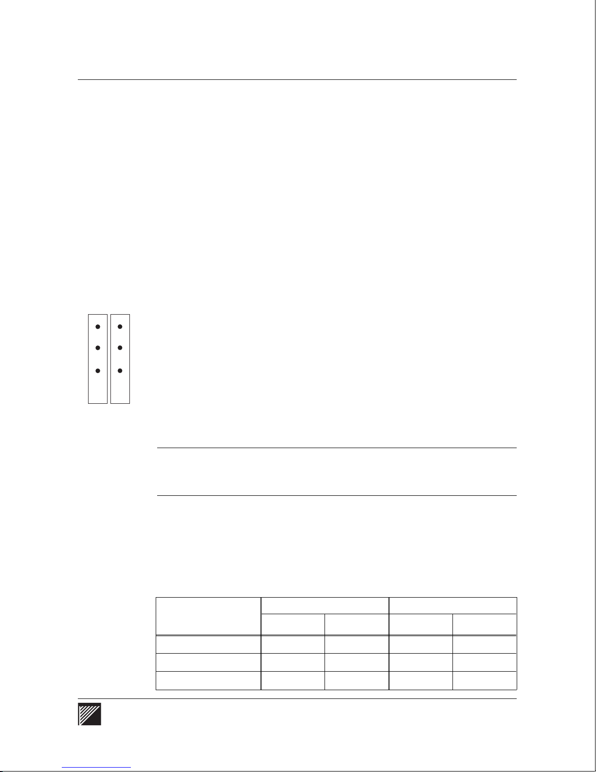
External Port Data window (Eport Stats)
The External Port Data window shows traffic and error information for each
user-accessible network port on the WaveSwitch 100.
To see the external port data, press F2.
The data for each port appears under the numbered heading that corresponds
to the port number on the front of the unit.
The two option slots hold feature modules that can provide up to four ports
per module, giving a maximum of eight additional ports. See Figure 1 on
page 7.
Table 4 shows the port numbers assigned to the two option slots according
to the number of fixed Ethernet ports on the base unit.
Console window commands
OPTION SLOT
BASE PORT
17
21
The base port number (low port) for each slot appears on the legend on the
front of the unit. The example shows the legend for a WaveSwitch 100 with
16 fixed Ethernet port s.
Note: The data for feature modules that provide fewer than four ports is
displayed beginning with the lowest numbered port assigned to the slot
(base port).
You can scroll the window using the up-arrow and down-arrow keys. The
ports are displayed according to their port groups: 1-4, 5-8, 9-12, 13-16,
17-20, and 21-24.
IMPORTANT — The display screen always shows headi n gs for the maximum
number of ports that can be installed on the unit. However, data appears
only under the headin gs that have instal led ports.
Table 4
Port num b er s a re ass i gn e d to m o dules in the optio n sl ot s a ccording to the number of
fixed Ether net port s on the uni t
Number of fixed
Ethernet ports on the
base unit
Option slot 1 Option slot 2
Base port High port Base port High port
8 9 12 13 16
12 13 16 17 20
16 17 20 21 24
WaveSwitch 100 Ethernet Switch User Manual 59
Page 82

Console window commands
State
This field indicates if the port is not present or gives its spanning tree state.
The field entry is one of the following: Not Present, Listening, Lear ning,
Blocked, Forwarding, Disabled.
Rx Frames
This field shows the number of data frames that were received on this port
and accepted for forwarding by the bridging hardware. The number reflects
activity since the start of operation of the WaveSwitch 100.
A port with no network connected indicates at least one frame, due to
self-testing. The number in this field can reach a maximum value of 232– 1
after which it is reset to 0.
Tx Frames
This field shows the number of data frames that were transmitted on this
port since the WaveSwitch 100 began operation. A port with no network
connected indicates at least one frame, due to self-testing. This number can
reach a maximum value of 232– 1 after which it is reset to 0.
Rx Frames/Sec
This field shows the rate at which frames were received on this port, based
on the average number of frames received during the last second.
Tx Frames/Sec
This field shows the rate at which frames were transmitted over this port,
based on the average number of frames transmitted during the last second.
Filter Discards
This field shows the number of frames received on this port that were
discarded due to the normal filtering action of the bridging hardware. The
number reflects activity since the start of operation of the WaveSwitch 100.
FCS Errors
This field shows the number of frames received on this port that contained
Frame Check Sequence Errors, indicating corrupted data. The number
reflects activity since the start of operation of the WaveSwitch 100.
Time Exceed ed
This field shows the number of frames received on this port that exceeded
the maximum permitted transit delay through the WaveSwitch 100. The
number reflects activity since the start of operation of the WaveSwitch 100.
60 WaveSwitch 100 Ethernet Switch User Manual 12195
Page 83

Internal Port Data window (Iport Stats)
Each bridging circuit of the WaveSwitch 100 provides a maximum of five
ports. Of these, one port connects to the internal backplane and up to four
ports are used for external network connections. Each bridging circuit
implements a group of ports (one internal network port, and either four
external Ethernet ports or one external high-speed port).
The Internal Port Data window shows information about the performance of
the internal port, which is connected to the backplane of the WaveSwitch
100.
To see the internal port data, press F3.
State
This field shows the operational state of the port. This is one of two values:
Not Present or Forwarding.
Rx Frames
This field shows the number of data frames received on this port that were
accepted by the bridging hardware for forwarding to one or more external
ports. The number reflects activity since the start of operation of the
WaveSwitch 100.
Console window commands
This number can reach a maximum value of 232– 1 after which it is reset to 0.
Tx Frames
This field shows the number of data frames transmitted to the backplane on
this port since the WaveSwitch 100 began operation.
This number can reach a maximum value of 232– 1 after which it is reset to 0.
Rx Frames/Sec
This field shows the rate at which frames were received on this port, based
on the average number of frames received during the last second.
Tx Frames/Sec
This field shows the rate at which frames were transmitted over this port,
based on the average number of frames transmitted during the last second.
Filter Discards
This field shows the number of frames received on this port that have been
discarded due to the normal filtering action of the bridging circuit . The
number reflects activity since the start of operation of the WaveSwitch 100.
WaveSwitch 100 Ethernet Switch User Manual 61
Page 84

Console window commands
FCS Errors
This field shows the number of frames received on this port that contained
Frame Check Sequence Errors, indicating corrupted data. The number
reflects activity since the start of operation of the WaveSwitch 100.
Time Exceed ed
This field shows the number of frames received on this port that exceeded
the maximum permitted transit delay through the WaveSwitch 100. The
number reflects activity since the start of operation of the WaveSwitch 100.
62 WaveSwitch 100 Ethernet Switch User Manual 12195
Page 85

Console menu commands
The System Commands menu displays the commands you can use on the
WaveSwitch 100.
To view the system commands menu, press F4.
To select a command, use the up-arrow and down-arrow keys to position the
selector bar over the command, then press ENTER.
To close the menu without selecting a command, press F1.
Reset Counters
This command resets the port counters to 0 in the External Port Data
(Eport Stats) and Internal Port Data (I port Stat s) windows. You can reset
the counters at any time when the console is running.
Erase Non-Volatile Store
This command erases any data in the nonvolatile data store of the
WaveSwitch 100, such as SNMP configuration information and permanent
static filter database entries.
Console menu commands
When you select the Erase Non-Volatile Store command, the configuration
and database entries in the WaveSwitch 100 are restored to the values that
were set at the factory before the unit was shipped.
Note: The message “Please wait while updating non-volatile store ”
appears during this process.
Turn On Aging/Turn Off Aging
This command toggles between On and Off and sets the SNMP variable
chassisAgeFilterDatabase.
Turn On Aging sets the SNMP variable chassisAgeFilterDatabase to Yes.
This enables filter database aging.
Turn Off Aging sets the SNMP variable chassisAgeFilterDatabase to No.
This suppresses all aging of filter database entries.
Note: No is the default value of this variable.
The Filter Database Aging field in the System Data window indicates
whether aging is off (suppressed) or on (enabled) in the WaveSwitch 100.
This field is updated whenever the aging state is changed, either through
SNMP or the console. See Figure 13 on page 57.
WaveSwitch 100 Ethernet Switch User Manual 63
Page 86

Console menu commands
Confi gu re Man agement
This command opens the Management Configuration window, which
enables you to datafill the screen to configure the WaveSwitch 100 locally.
The data you enter in the fields is written to the configuration file of the
WaveSwitch 100.
For more information, see “Dataf illi ng the configurati on fields” on page 82.
Display Address Canonically/Display Address Non-canonically
This command toggles between Ethernet and FDDI formats for the
addresses that are displayed in the Base MAC Address field of the
System Data window of the console.
The default display mode is canonical, which is the standard Ethernet
address format. The non-canonical display mode shows the address in
FDDI format. For more information, see “Port address formats” on page 66.
When the 6-byte Base MAC Addresses are displayed canonically
(in Ethernet for mat) there is a hyphen (-) after the first three bytes. When
the addresses are displayed non-canonically (in FDDI format) there is a
colon (:) after the first three bytes. See Figure 13 on page 57.
Frame Loss Incident Report
This command opens the Frame Loss Incident (FLI) Report window. The
report shows FLIs for each external port and the backplane.
Note: A FLI indicates that one or more frames have not been forwarded
due to a lack of resources. A FLI is not a count of actual frames lost.
The FLI report shows the total number of FLIs for each external port and
the backplane since the unit was reset (powered on). It also shows the
number of FLIs for each external port and the backplane since the last
update (Delta FLI), the time elapsed since the last update, and the state of
each port at the time of update. The report always shows headings for the
maximum number of ports that can be installed on the unit.
When you open the FLI report window, an automatic update takes place.
The initial values are for the period between the last update and the time you
chose the Frame Loss Incident Report command.
To update the FLI report, press F1. The system marks the time since the last
update and displays the update period. The Total FLI, Delta FLI, and State
fields are also updated. See Figure 14 on page 65.
64 WaveSwitch 100 Ethernet Switch User Manual 12195
Page 87

Figure 14
The Frame Loss Incident (FLI) Report for a 16-port base unit
Console menu commands
Port State Total FLI Delta FLI Port State Total FLI Delta FLI
1 Fwd 0 0 13 Fwd 0 0
2 Fwd 0 0 14 Fwd 0 0
3 Fwd 0 0 15 Fwd 0 0
4 Fwd 0 0 16 Fwd 0 0
5 Fwd 0 0 17 - - 6 Fwd 0 0 18 - - 7 Fwd 0 0 19 - - 8 Fwd 0 0 20 - - -
9 Fwd 0 0 21 D/C 0 0
10 Fwd 0 0 22 - - 11 Fwd 0 0 23 - - 12 Fwd 0 0 24 - - Backplane 0 0
Time since last FLI update: 0:00:02:47
Fwd Forwarding Lst Listening Lrn Learning
Blk Blocking D/A Disabled D/C Disconnected
Cls Closed - Not Present
F1-Update F2-Done
Frame Loss Incident (FLI) Report
Ctrl-X: Exit
WaveSwitch 100 Ethernet Switch User Manual 65
Page 88

Port address formats
Port address formats
There are two address formats used to designate ports in the WaveSwitch
100:
• Ethernet ports (IEEE Canonical format)
• FDDI ports (non-Canonical format)
Ethernet port addresses
The IEEE Medium Access Control (MAC) addresses of the Ethernet ports
are calculated from Ethernet port 1 (Base MAC Address). The Base MAC
Address is in Canonical format.
The method of calculating each port address is shown below. The Ethernet
address of the specific link is identified by the rightmost octet.
MAC address Ethernet po rt
AA-BB-CC-DD-EE-30 1
AA-BB-CC-DD-EE-31 2
AA-BB-CC-DD-EE-32 3
AA-BB-CC-DD-EE-33 4
AA-BB-CC-DD-EE-34 5
AA-BB-CC-DD-EE-35 6
AA-BB-CC-DD-EE-36 7
AA-BB-CC-DD-EE-37 8
AA-BB-CC-DD-EE-38 9
AA-BB-CC-DD-EE-39 10
AA-BB-CC-DD-EE-3A 11
AA-BB-CC-DD-EE-3B 12
AA-BB-CC-DD-EE-3C 13
AA-BB-CC-DD-EE-3D 14
AA-BB-CC-DD-EE-3E 15
AA-BB-CC-DD-EE-3F 16
66 WaveSwitch 100 Ethernet Switch User Manual 12195
Page 89

FDDI port addresses
The station address of each FDDI feature module is assigned at the factory.
The address has the form AA-BB-CC-xx-xx-xx.
A FDDI station address can be represented in the IEEE Canonical format,
for example AA-BB-CC-87-65-43, or it can be represented in FDDI format
(non-Canonical).
To derive the FDDI format (non-Canonical), read the binary notation for
each octet (pair of hexadecimal values) in reverse order and convert the
result into a new pair of hexadecimal values.
binary notation
hexadecimal notation
IEEE Canonical format
1000 0111
8 7
FDDI non-Canonical format
1110 0001
E 1
Port address formats
reverse binary notation
new hexadecimal notation
WaveSwitch 100 Ethernet Switch User Manual 67
Page 90

About SNMP
About SNMP
Simple Network Management Protocol (SNMP) is a set of network
management protocols and functions that communicate using the Internet
Protocol (IP) stack.
Under SNMP, managed entities such as routers, concentrators, and host
computers contain software components called agents. The agent monitors
the operation of the managed entity. To do this, the agent maintains a
collection of variables, called objects, in the Management Information
Base (MIB). The MIB reflects the operation of the managed entity.
A manager program, which normally runs on a network station, exchanges
messages with the agent to access the agent’s MIB. The manager reads
from, and writes to, objects in the MIB according to predefined access
privileges that have been assigned to the MIB objects. SNMP defines the
protocols and message formats that are used to perform the read and write
operations; these are called gets and sets, respectively.
When the manager sets a MIB object to a new value, the agent responds by
altering the operation of the managed entity in some way, such as disabling
a port or running a self-test. While the agent does not normally transmit the
contents of its MIB objects without first being queried by the manager, the
occurrence of an exceptional event raises an alarm called a trap. A trap is
an unsolicited message containing information about the event.
The manager must know the structure of the MIB that the agent implements
to understand object names, object types, what the objects represent, and the
permissible types of access to the objects.
This structural information is provided to the manager by using
• Internet standard MIBs
• private (enterprise-specif ic) MIBs
The main Internet standard MIB is called MIB-II. It provides an abstract
view of the operation of the managed entity, and applies to all agents.
Another standard MIB is the Bridge MIB, which provides specialized
management functions for transparent and source routing bridges.
Private MIBs permit the management of individual manufacturers’
equipment.
The WaveSwitch 100 contains a limited SNMP manager that gives you
access to the SNMP agent; for small LANs, you may not need additional
software. However, if you have a LAN that requires a large-scale SNMP
application, the WaveSwitch 100 SNMP manager and agent are compatible
with third-party managers.
68 WaveSwitch 100 Ethernet Switch User Manual 12195
Page 91

SNMP and the WaveSwitch 100 Ethernet Switch
The WaveSwitch 100 supports MIB-II, IEEE 802.1d Bridge MIB, and
FDDI MIB standards. Any management station that implements these
standards can monitor and control a WaveSwitch 100 without incorporating
the WaveSwitch 100 Private MIB.
Using the Bridge MIB, managers can enable and disable ports, control the
operation of the Spanning Tree Protocol, control the fil teri ng behavior of the
bridge, and modify the contents of the filter database. Managers can also
monitor the traffic perfor mance of the WaveSwitch 100.
Using the WaveSwitch 100 Private MIB, managers can get more
information about the WaveSwitch 100 and exercise more control over its
operation.
For information about the MIBs, MIB objects, and their default values, see
“WaveSwitch 100 MIBs and traps” on page 113.
The WaveSwitch 100 Ethernet Switch SNMP agent
The SNMP agent is part of the standard WaveSwitch 100 software. The
agent uses the WaveSwitch 100 network interfaces to exchange SNMP
frames with managers over the network payload data streams.
About SNMP
The SNMP agent maintains the MIB in the WaveSwitch 100 by updating
MIB objects as events occur within the WaveSwitch 100. The agent also
monitors the read/write objects in the MIB, using them as action requests.
If a manager changes a MIB object, the agent takes action according to the
new value of the object.
The SNMP agent is active while the WaveSwitch 100 operates. No special
action is required to enable the agent, although some configuration
information is needed to make the agent fully operational.
WaveSwitch 100 Ethernet Switch User Manual 69
Page 92

About configuration information
About configuration information
The SNMP agent needs configuration information that it cannot determine
on its own. Some configuration information is required for the agent to
operate properly, and some of it is optional.
The following informati on can be supplied to the agent during configuration:
• IP address
• manager community names, IP addresses, and access privileges
• trap community names and IP addresses
• default gateway IP address
• number of bits in the subnet mask
• name of the unit
• location of the unit
• contact person
IP address
Unlike Ethernet addresses, the IP addresses of network nodes—especially
within private LAN s—do not need to be universally administered.
IP addresses are typically assigned for a site by the network administrator,
and can change over time.
When the manager is on the same IP network as the WaveSwitch 100, only
the IP address of the unit is needed to make the SNMP agent operational. If
the address is the only information given for an agent, managers are
restrict ed to the use of the PUBLIC community, and the agent will not issue
traps.
Manage r communit y names, IP addresse s, and access privileges
A manager community contains an SNMP agent and one or more managers.
Each manager community is identified by a unique name. An agent can
belong to up to 10 manager communities at the same time.
Each manager community has an IP address to which the agent sends its
communications. Each community can also have a privilege level that
specifies what type of access the member managers have to the MIB object s.
If a manager community has the default access privilege of read-only,
managers can read (get) all MIB objects, but cannot write (set) any of them.
If a community has read/write privileges, managers can get all objects and
set only those that are defined to have read/write access.
The agent recognizes, without configuration, the default community
PUBLIC, which has read-only privileges.
70 WaveSwitch 100 Ethernet Switch User Manual 12195
Page 93

Trap community names and their IP addresses
If an exceptional condition in the WaveSwitch 100 generates a trap, the
agent needs to know where to send the trap message. The agent gets this
information from its membership in trap communities.
Trap communities are similar to manager communit ies, except that trap
communitie s have no associated privilege level. Trap community names
can be the same as manager community names.
The agent can belong to up to 10 trap communities at the same time. If no
trap community is configured, the agent will not issue traps.
Default gateway IP address
If the IP address of an incoming SNMP message indicates that the manager
resides on a different network from the agent, the agent uses the default
gateway IP address to send the reply to the proper node for transfer to the
manager’s network.
Number of subnet bits
An IP address consists of two parts:
About configuration informatio n
• the network part, which identifies the network to which a device is
attached
• the host part, which identifies the device itself
Depending on the class of address, the network ID can use 8, 16, or 24 bits
of the 32-bit address:
• Class A addresses have an 8-bit network number and a 24-bit host
number
• Class B addresses have a 16-bit network number and a 16-bit host
number
• Class C addresses have a 24-bit network number and an 8-bit host
number
The network part of the address always begins with the first number of the
IP address. For example, in the Class B address 129.1.2.3 the network
number is 129.1 and the host number is 2.3.
However, a simple IP address does not provide enough flexibility to
separate a large network into communities of interest or to keep Ethernet
collision domains small. To meet these objectives, you must partition the
large network into smaller subnetworks.
Subnetworks are created by dividing the host part of the IP address into two
fields – the subnet part and the host part. The subnet part is a series of
WaveSwitch 100 Ethernet Switch User Manual 71
Page 94
About configuration information
contiguous bits that begin immediately after the network part of the original
IP address and extend into the host part of that address.
Subnetworks are indicated by the presence of a subnet mask in the device.
A subnet mask has the same format as an IP address, but all the bits of the
network and subnet parts are 1. All the bits of the host part are 0. For
example, if the manager of a network with Class B addresses wanted to
create eight subnetworks, the subnet mask would be 255.255.224.0.
The subnet mask for the WaveSwitch 100 is specified by giving the number
of bits of the host part of the IP address that are to be used in the subnet
mask.
Permissible values are 1 through 16, allowing the specification of up to
65536 subnetworks, depending on the class of the original IP address.
The following table contains examples of subnet masks for different classes
of network addresses.
Class
Network
address
Number
of
subnets
Subnet
bits Subne t ma sk
Value
entered
A 40.0.0.0 4096 12 255.255.240.0 12
B 129.1.0.0 1024 10 255.255.255.192 10
C 193.1.1.0 16 4 255.255.255.240 4
Name
This is an ASCII text string that identifies the WaveSwitch 100 to users of
the management software, such as Accounting Ethernet Switch #2.
Location
This is an ASCII text string that gives the physical location of the unit, such
as Second Floor, Equipment Bay 3.
Contact person
This is an ASCII text string that gives the name of the person, department,
or company to contact about the operation of the WaveSwitch 100, for
example, John Smith, Premium Networ k s Inc., 555-1234.
72 WaveSwitch 100 Ethernet Switch User Manual 12195
Page 95

Datafilling the configuration fields
The previous section, “About configuration information,” describes the
types of information the SNMP agent uses to manage a WaveSwitch 100.
This section gives the rules for entry of configuration data that you can enter
directly into the WaveSwitch 100 using the Management Configuration
window of the console (Figure 15) or load remotely from a configuration
file you load onto a network station.
To configure the WaveSwitch 100 locally, see page 77.
To configure the WaveSwitch 100 remotely, see page 79.
IP address
The line specifying the IP address has the following format:
IP address: <ip_address>
The IP address is specified in Internet standard dot notation. The numbers
in the address are in decimal in the range of 0 to 255. Sample addresses are
192.1.1.15, or 2.155. 7.45.
Datafilling the configuration fields
For information about assigning IP addresses, see Internetworking with
TCP/IP, Volume 1, Principles, Protocols, and Architecture, by Douglas E.
Comer (Englewood Cliffs, NJ: Prentice-Hall, 1991).
Figure 15
The Management Confi guratio n wind ow of the Syst em Manage r (SYSMAN)
Up Time: 0:00:04:55__Plaintree WaveSwitch 100 System Manager
IP address: 0.0.0.0
Default gateway address: 0.0.0.0
Number of subnet bits: 0 Subnet Mask: 255.0.0.0
Name: Uninitialized
Location: Uninitialized
Contact: Uninitialized
Management Communities:
public 0.0.0.0
Trap Communities:
F1-Commit Changes F2-Ignore Changes Ctrl-X: Exit
WaveSwitch 100 Ethernet Switch User Manual 73
Page 96

Datafilling the configuration fields
Manager community name
A manager community name entry has the following format:
Management Communities: <name_string> [ip_address] [RW]
The name string is a single word identifying the community. The maximum
length of the community name is 63 characters.
The IP address and privilege are optional. If an IP address is not included,
the agent sends responses for a given community to the IP address of the
manager that made the request.
RW gives the community read/write access to MIB objects for which
read/write privi leges are defined. If RW privileges are not included, the
community has read-only access to the agent’s MIB.
Specifiying an entry with IP address 0.0.0.0 indicates that any manager with
the entry’s community name will have the associated privileges.
Because the configuration information can contain multiple manager
community entrie s, each subsequent entry (to a maximum of 10) is added to
the list of communities recognized by the agent.
The manager community public 0.0.0.0 is predefined and cannot be changed.
Trap community name
A trap community name entry has the following format:
Trap Communities: <name_string> <ip_address>
The name string is a single word identifying the trap community. The
maximum length of the trap community name is 63 characters.
The IP address is the address of the manager that receives traps for that
community.
Because the configuration information can contain multiple trap-comm unity
entries, each subsequent entry (to a maximum of 10) is added to the list of
communitie s recognized by the agent.
Default ga teway address
The gateway address entry has the following format:
Default gateway address: <ip_address>
The specified IP address is the address of the network node which functions
as the default gateway for the network.
74 WaveSwitch 100 Ethernet Switch User Manual 12195
Page 97

Datafilling the configuration fields
Number of subnet bits
The subnet entry has the format:
Number of subnet bits: <number>
Enter a decimal number from 0 through 16. When you enter a number in
the Number of subnet bits: field, the field next to it displays the resulting
Subnet Mask.
Name
The name entry has the format:
Name: <string>
The string can consist of multiple words, and must not be enclosed in
quotes. The string can be up to 63 characters long.
Location
The location entry has the format:
Location: <string>
The string can consist of multiple words, and must not be enclosed in
quotes. The string can be up to 63 characters long.
Contact perso n
The contact entry has the format:
Contact: <string>
The string can consist of multiple words, and must not be enclosed in
quotes. The string can be up to 63 characters long.
WaveSwitch 100 Ethernet Switch User Manual 75
Page 98

Configuration procedures
Configuration procedures
There are two methods you can use to configure a WaveSwitch 100:
• local configuration
• remote configurati on
When a WaveSwitch 100 powers up, it checks its non-volatile memory for
previously-loaded configuration information. If it does not find the
configuration infor mati on it needs in memory, the WaveSwitch 100 requests
remote configurati on over the network.
Note: The WaveSwitch 100 is supplied without configuration
information in memor y, so its default behavior is to request remote
configuration.
76 WaveSwitch 100 Ethernet Switch User Manual 12195
Page 99

Configuring a WaveSwitch 100 Ethernet Switch locally
Configuring a WaveSwitch 100 Ethernet Switch locally
You can configure a WaveSwitch 100 locally using a VT100 terminal—or a
workstation or PC running a VT100 emulator—connected to the
WaveSwitch 100 with an RS232 cable. For information about the
hardware, software, and system set-up requirements, see page 49.
To configure a WaveSwitch 100 locally, follow the steps below.
Step Action
1
Connect the VT100 terminal to the PC/MODEM port on the
WaveSwitch 100 using a straight-through RS232 cable. Make sure
both units are powered on.
Note:
No network connection is needed for local configuration.
2 Press RETURN to start the console. If the system is already
running and the cursor is on the command line of the VT100
terminal, type
SYSMAN
and press RETURN
3 Press F4 to see the System Commands menu.
4 Choose Configure Management from the Systems Command menu.
5 For each field you want to datafill, type the data into the area next
to the field label and press RETURN. Use BACKSPACE to make
corrections when you are datafilling a field.
Note:
If the data you entered is valid, the field is updated; if the
data you entered is not valid, the value that was previously entered
in the field appears.
6 Press TAB to move the cursor to the next field.
7 Use the up-arrow and down-arrow keys to scroll in the Management
Communities and Trap Communities fields. The display shows a
maximum of three entries in the communities fields; you can scroll
the field to view or edit entries, or to enter additional entries.
8 When you have finished entering or editing data in the Management
Configuration window, press F1 to commit the changes to
nonvolatile store, or press F2 to ignore the changes.
Note:
When you press F1, the message “Please wait while
updating nonvolatile store” is displayed at the bottom of the screen
until the update is completed.
end
WaveSwitch 100 Ethernet Switch User Manual 77
Page 100

Configuring a WaveSwitch 100 Ethernet Switch locally
Configuration infor mation is stored in non-volatile memor y in the
WaveSwitch 100. If it is powered off and restarted, the unit automatically
reads the configuration information from its memory.
CAUTION — Make sure you keep a copy of the current configuration
information. There are no internal safeguards in the WaveSwit ch 100 against
overwriting the con figuration information.
You may need to change configuration information in the WaveSwitch 100.
Some of the configuration data, such as name, location, and contact, can be
changed using SNMP. Other data, such as IP address and communities
information, cannot be changed while the unit is in operation.
To change IP address and communities information, enter or edit the data in
the Management Configuration window in the console. The WaveSwitch
100 stores the new information in memory.
78 WaveSwitch 100 Ethernet Switch User Manual 12195
 Loading...