


Instruction Manual
DS25
All metal variable area flowmeter,
insensitive to viscosity changes
PKP Prozessmesstechnik GmbH
Borsigstraße 24
D-65205 Wiesbaden-Nordenstadt
Tel.: ++49-(0)6122-7055-0
Fax: ++49-(0)6122-7055-50
Email: info@pkp.de

Table of Contents
Safety Information................................................................................................................................2
Device Description...............................................................................................................................4
Installation in the pipeline....................................................................................................................6
Electrical Connection...........................................................................................................................6
Connection Diagrams...........................................................................................................................9
Start of operation................................................................................................................................11
Limit switches.....................................................................................................................................12
Electronic Transmitter........................................................................................................................14
Selection of indication function (F11)................................................................................................18
Setting the unit (F12 / F13).................................................................................................................19
Totalizer reset (F14)...........................................................................................................................21
Selection of temperature unit (F15)....................................................................................................21
Setting of damping (F2-)....................................................................................................................22
Selection / Adjustment 4-20 mA / 0-20 mA (F3-)..............................................................................23
Error messages (F4-)...........................................................................................................................24
Manual adjustment (F5-)....................................................................................................................25
Revision indication (F61/F62)............................................................................................................29
Current output test (F63)....................................................................................................................29
Switching between standard / Indicator on extension (F64)...............................................................30
Master Reset (F65).............................................................................................................................30
Float blocking indication (F7-)...........................................................................................................31
Service and Maintenance....................................................................................................................36
Safety Information
General Instructions
To ensure safe operation, the device should only be operated according to the specifications in the
instruction manual. The requisite Health & Safety regulations for a given application must also be
observed. This statement also applies to the use of accessories.
Every person who is commissioned with the initiation or operation of this device must have read
and understood the operating instructions and in particular the safety instructions!
The liability of the manufacturer expires in the event of damage due to improper use, nonobservance of this operating manual, use of insufficiently qualified personnel and unauthorized
modification of the device.
DS25 Instruction Manual 08/2018 page 2

Proper Usage
The variable area flow meter DS25 are designed to measure and monitore continuous flow rates of
liquids or gases which do not attack the device materials. All other usage is regarded as being
improper and outside the scope of the device.
In particular, applications in which shock loads occur (for example, pulsed operation) should be
discussed and checked in advance with our technical staff.
The series DS25 flow meter devices should not be deployed as the sole agents to prevent dangerous
conditions occurring in plant or machinery. Machinery and plant need to be designed in such a
manner that faulty conditions and malfunctions do not arise that could pose a safety risk for
operators.
Dangerous substances
For dangerous media such as e.g. Oxygen, Acetylene, flammable or toxic substances as well as
refrigeration systems, compressors, etc. must comply with the relevant regulations beyond the
general rules.
Qualified Personnel
The DS25 devices may only be installed by trained, qualified personnel who are able to mount the
devices correctly. Qualified personnel are persons, who are familiar with assembling, installation,
placing in service and operating these devices and who are suitably trained and qualified.
Inward Monitoring
Please check directly after delivery the device for any transport damages and deficiencies.
Additional with reference to the accompanying delivery note the number of parts must be checked.
Claims for replacement or goods which relate to transport damage can only be considered valid if
the delivery company is notified without delay.
DS25 Instruction Manual 08/2018 page 3

Device Description
Explanations of specifications on flanges
• type of flange e.g. DIN
• size of flange e.g. DN15
• Pressure range of flange and measuring tube e.g. PN40
• Material of wetted parts e.g. 1.4404
• Manufacturing code of flange manufacturer
• Lot. No.
DS25 Instruction Manual 08/2018 page 4

Scale example for Display
Scale example for Display with electronic transmitter
DS25 Instruction Manual 08/2018 page 5

Installation in the pipeline
• Be sure to remove the transport lock card-board strip from the measuring tube. Check that
no cardboard remains in the tube.
• The DS25 flow rate meter must be installed in a vertical pipeline, in which the medium
flows upwards. The vertical position has to be checked at the outer edge of the flanges.
• Bigger nominal diameters (DN 80 / DN 100) require straight pipe sections of at least 5D in
front and behind the DS25.
• The nominal diameter of the DS25 should correspond to the nominal diameter of the
pipeline.
• To avoid stress in the connecting pipes, the connecting flanges must be aligned in parallel
and axial direction.
• Bolts and gaskets have to be selected according to the maximum operating pressure, the
temperature range and corrosion conditions.
• Center gaskets and tighten nuts with a torque appropriate for the pressure range.
• If contamination or soiling of the DS25 is to be expected, a bypass should be installed to
allow the removal of the instrument without interruption of the flow.
Tightening of the flange threads for DS25 with PTFE- liner with the following torques:
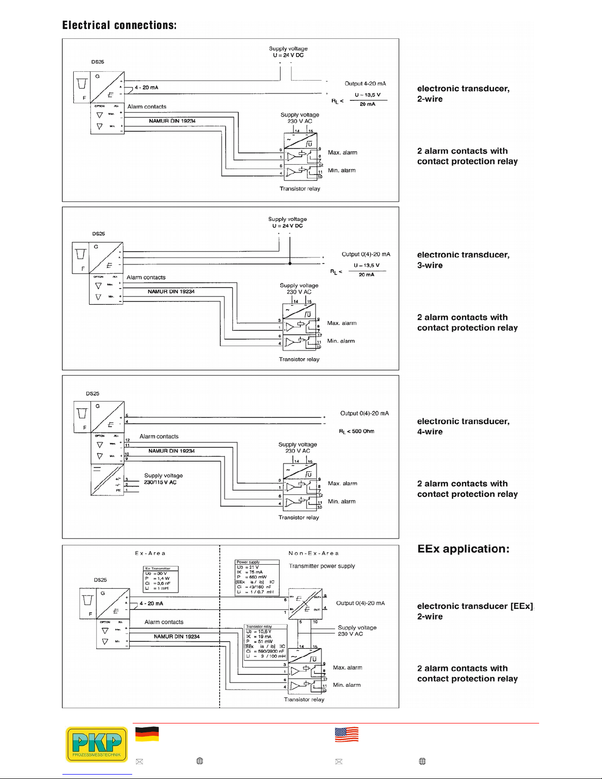
Electrical Connection
Please regard the drawings on the following pages.
• On the rear of the DS25 are two cable glands for round cables with a diameter of 6 to 9 mm
• Unused glands must be closed with a blind plug M16x1.5.
• Wires should not be bent directly at terminal screws.
• Do not expose wires to mechanical pressure.
• Wires must be arranged according to common installation rules, especially signal and power
lines must not be bundled together.
• Cables should not be bend directly after the cable gland. Do not fix cable at the measuring
tube.
• The DS25 terminals accept wires with a maximum sectional area of 1.5 mm²
DS25 Instruction Manual 08/2018 page 6

• The attached ferrite core must be mounted
on the cable as shown on the below
picture. Distance "L" < 2 cm.
• Measuring and indicating instruments,
connected in series to the output of the
electronic transmitter, must not exceed a
load impedance of
RL = (U - 13.5 V) / 20 mA
for 2-/3-wire or 500 Ω for 4-wire
• 2- or 3-wire units are connected to the
terminals marked “+”, “-” and “A” of the
power connector.
• For 2-wire instruments the terminals “-”
and “A” have to be shorted with a jumper.
Take care not to loose that jumper when mounting wires.
• Wiring inside the case should be kept as short as possible to avoid that moving parts are
blocked.
Attention: Hints for Unit Safety (according DIN EN 61010-1)
• Do not connect cables outdoors in wet weather in order to prevent damage from
condensation and to protect the insulation, e.g. inside the terminal box of the flowmeter.
• Heed the nominal voltage indicated on the scale.
• Use the cables which fulfill specification and check before wiring.
• The electrical connections have to be executed according to VDE0100 “Errichten von
Starkstromanlagen mit Nennspannungen bis 1000 V” (Installation of high current assemblies
with nominal voltages of up to 1000 V) or equivalent national regulations.
• For units with a nominal voltage of 115 V or 230 V the correspondingly marked terminal
has to be connected to protective earth (PE).
• Units with a nominal voltage of 24 V may only be connected to a protected low voltage
circuit (SELV-E according to VDE0100/VDE 0106 or IEC 364/IEC 536).
• The DS25 indicator housing must be grounded to ensure electromagnetic interference
protection. This can be done by grounding the pipeline.
• Once all wiring is complete, check the connections before applying power to the instrument.
Improper arrangements or wiring may cause a unit malfunction or damage.
• This unit does not include a power switch. Therefore, a switch has to be prepared at the
installation location in the vicinity of the unit. The switch should be marked as the power
separation switch for the DS25.
DS25 Instruction Manual 08/2018 page 7

2 wire unit:
4 wire unit:
DS25 Instruction Manual 08/2018 page 8

Connection Diagrams
DS25, 2-wire unit with limit switches and transmitter relay:
DS25, 3-wire unit with limit switches and transmitter relay:
DS25 Instruction Manual 08/2018 page 9

DS25, 4-wire unit with pulse output:
DS25, 2-wire unit with HART-communication, with limit switches and transmitter relay:
DS25 Instruction Manual 08/2018 page 10

Start of operation
Hints on flow rate measurement:
The measured fluid should neither consist of a multi-phase mixture nor contain ferrite ingredients or
large solid mass particles.
Hints on scale:
The DS25 scale is adjusted to the state of operation/aggregation of the measured fluid by the
manufacturer. If the state of operation changes, it might become necessary to establish a new scale.
This depends on several factors:
• If the DS25 is operated in the given viscosity independent range, only the density of the float
as well as the operational density of the previous and new substance have to be considered.
• In case the operational density only changes marginally (≤ 0.5 %), the present scale can be
used.
• If the DS25 is operated outside the given viscosity independent range, the viscosities at the
previous and new state of operation as well as the mass and diameter of the float have to be
taken into account.
Pulsation and pressure shock:
Pressure shock waves and pulsating flow influence measurement significantly or can destroy the
meter. Surge conditions should be avoided. (open valves slowly, raise operating pressure slowly)
If float bouncing occurs in gases increase the line pressure until the phenomena stops. If this is not
possible provide the float with a damper. A damping kit is available as spare part.
Start of operation of electronic transmitter:
Ensure that the device has been connected correctly and that the used power supply meets the
requirements indicated on the scale.
Switch on the power supply.
The digital display gives the totalizer value in the measuring unit, indicated on the right side of the
display.
The DS25 is now ready for operation.
Unit graduation, measuring unit, damping, etc. can be adjusted by an operating menu.
In case of an error, the bars beneath the 8 digits of the display will flash. The corresponding error
message can be checked using the operating menu and then taking the appropriate counter measures
(refer to section “Error Messages”).
The transmitter has been prepared and calibrated according to the model code as a 2-, 3- or 4-wire
unit.
DS25 Instruction Manual 08/2018 page 11

In 2-wire units, a jumper connects “A” and “-”. When switching from a 2- to a 3-wire configuration,
this jumper should be removed. The current output should then be adjusted.
When changing from a 3- to 2-wire configuration, the jumper should be set in place, and the current
output has to be adjusted.
Limit switches
The optional limit switches are available as maximum or minimum type switches. They are
proximity switches according to EN 60947-5-6 (NAMUR). Maximum two switches can be
installed. As transmitter relay we recommend our model P+F.
The limit switches have to be connected to the transmitter relays.
The terminals for the limit switches are on a small board on top of the transmitter case.
Use of 2 standard limit switches:
The MIN-MIN and MAX-MAX functions have been integrated at the factory as MIN-MAX
switches in the DS25.
The MIN-MIN or MAX-MAX function is set by adjusting the switching direction of the transmitter
relay.
The following table shows the assignment:
Function
Switching direction of transmitter relay
Chanel 1 Chanel 2 Chanel 1 Chanel2
MIN MAX S1 position I S2 position I
MIN MIN S1 position I S2 position II (ON)
MAX MAX S1 position II (ON) S2 position I
DS25 Instruction Manual 08/2018 page 12

Adjusting the switching points:
To adjust the switching points, loosen set screws 1 and 2 and move them in the guide rail. The small
red pointers (Limit switch MAX and Limit switch MIN) indicate the set value on the scale.
DS25 Instruction Manual 08/2018 page 13

Electronic Transmitter
Operation principle:
The position of the float is magnetically transferred to a magnetic follow up system. The position
angle of this magnetic rocker is detected by magnet sensors. A micro controller determines the angle
by means of a combining reference value table in the memory and calculates the flow rate by the
angle with calibration and operation parameters the calibration EEPROM.
The flow rate is given as a current, either 0-20 mA or 4-20 mA, and, in addition, indicated on the
digital display (refer also to section 6-2). The electronic transmitters have been electronically
adjusted before shipping and, therefore, are mutually exchangeable.
Calibration data of the metering tube as well as customer specific data are entered into a calibration
EEPROM, inserted on the board. This calibration EEPROM and the indication scale are assigned to
the respective metering tube.
When replacing an indicator (e.g. because of a defect) the scale and calibration EEPROM of the old
unit have to be inserted in the new unit. Then, no calibrations or adjustments are necessary.
If an indicator with electronic transmitters is installed to a new metering tube, the calibration
EEPROM of that tube has to be inserted into the transmitter and the indicator scale for that
particular tube has to be mounted.
A change in the fluid data (e.g. specific gravity, pressure, etc.) requires the preparation and
mounting of a new calibration EEPROM and scale.
Normally the range of the current output is equal to the rounded measuring range of the tube (end
value on scale). The customer can position the 20 mA point between 60 % and 100 % of the end
value on scale. The set of the 20 mA point is shown on the scale. The flow cut off is positioned at
5 % of the end value. Below 5 % flow the current output shows 0 mA (4 mA).
DS25 Instruction Manual 08/2018 page 14

Parameter setting:
The displays allows indication of various parameters:
• Flow rate (8 mass or volume units in combination with 4 time units)
• Counter (8 mass or volume units)
• Flow rate indication in percent
• Special functions
• Setting of different damping times
• Switching of current output 0-20 mA / 4-20 mA or vice versa
• Indication of error messages
• Manual adjustment
• Service functions
• Detection of float blockage
The setting of these parameters is done by two buttons.
DS25 Instruction Manual 08/2018 page 15

The buttons access three functions:
• upper button ( ↑ ) : Exit setting mode
• lower button ( → ) : Scroll through menu/selection of parameters
• both buttons ( ↑ + → ) = Enter : Entering parameters/selecting setting mode
If no button is pressed for one minute while the operating menu is active, the indication reverts to
the measuring indication. This does not apply to subfunctions F32, F33, F52, F63.
For indication of volume or mass values at maximum 6 digits in front of the decimal point and 7
decimals are used. This format allows an indication range for flow rates from 0.0000001 unit/time
to 106000 unit/time.
Flow rate values exceeding 106000 are shown as ‘————’ on the display. In this case the next
bigger flow rate unit (next smaller time unit) has to be selected.
For the indication of totalizers values 8 digits are used at maximum of which 7 digits can be
assigned for decimal values. The decimal point setting is determined by selecting the unit.
Therefore, possible totalizer offsets are:
Unit x 1 Unit x 1/10 Unit x 1/100
The totalizer counts up to 99999999 or 9999999.9 or 999999.99 and is reset to zero.
The next page shows the operating menu.
The following describes selection and execution of functions.
Menu:
DS25 Instruction Manual 08/2018 page 16

DS25 Instruction Manual 08/2018 page 17

Selection of indication function (F11)
The function F11 selects the display’s indication function.
The following indications can be set: flow rate, totalizer, % value or temperature.
At the factory the display is preset to totalizer indication.
Note:
If you press “↑” instead of “Enter”, you can return from the selected point to the previous menu
without activating the displayed parameter.
When selecting “Flow rate” the measuring unit is set with function F12 and F13. When selecting
“Totalizer” the measuring unit is set with F12. If % indication is selected, F12 and F13 have no
effect. The internal totalizer is updated, if “Flow rate” or “Counter” is selected. In case of setting to
“%” the internal counter is not updated and keeps its previous value.
If "Temperature" is selected the unit can be set by function F15. The indicated value is the
temperature in the indication unit.
After changing the indicating function and measuring units the corresponding measuring unit label
should be fixed on the right side next to the display.
DS25 Instruction Manual 08/2018 page 18

Setting the unit (F12 / F13)
When ordering the transmitter two sets of metering units are available. It is not possible to switch
between them.
These two sets comprise the following metering units:
DS25 Instruction Manual 08/2018 page 19

With functions F12 and F13, the measuring unit for displayed value is selected.
F12 selects volume and mass units, while F13 sets the corresponding time unit.
When selecting the indication function “totalizer” the set time unit is not taken into account and
only the selected mass or volume unit is effective. When choosing the “%” indication F12 and F13
have no effect.
The selection of the measuring unit is performed as follows:
Note:
If you press “↑" instead of “Enter”, you can return from the selected point to the previous menu
without activating the displayed parameter.
After changing the measuring unit the corresponding measuring unit label should be fixed on the
right side
next to the display. A sheet with stickers is included.
Attention:
When switching the mass/volume unit the totalizer is reset to zero.
When changing the time unit the totalizer value remains unchanged.
DS25 Instruction Manual 08/2018 page 20

Totalizer reset (F14)
Function F14 resets the totalizer to zero.
The counter reset is performed as follows:
Note:
If you press “↑" instead of “Enter”, you can return from the selected point to the previous menu
without activating the displayed parameter.
Selection of temperature unit (F15)
The function F15 sets the unit of temperature indication.
The following indications can be set: degC (Celsius) or degF (Fahrenheit).
At the factory the display is set to degC indication.
The selection of the indication is as follows:
Note:
If you press “↑" instead of “Enter”, you can return from the selected point to the previous menu
without activating the displayed parameter.
DS25 Instruction Manual 08/2018 page 21

Setting of damping (F2-)
Function F21 allows damping the output with a certain time constant (63 % value). Normally the
time constant is set to 1 sec.
The selection of the time constant is as follows:
Note:
If you press “↑" instead of “Enter”, you can return from the selected point to the previous menu
without activating the displayed parameter.
DS25 Instruction Manual 08/2018 page 22

Selection / Adjustment 4-20 mA / 0-20 mA (F3-)
Function F3- sets the current output to 4-20 mA or 0-20 mA. In addition, offset and span have to be
readjusted. Offset compensation is for fine tuning the 0 or 4 mA point. Span or range compensation
is for precise adjustment of the 20 mA point.
For compensating the output, an ampere metre (mA) should be connected to the circuit loop. For
wiring refer to the diagrams in chapter 3.
The current output is set according to customer specifications at the factory.
Switching the output is executed as follows:
An adjusting step corresponds to 20 μA. The complete adjusting range is ± 0.62 mA (31 steps).
If the adjusting range does not suffice, change to display F32 or F33 by pressing ENTER when
display shows F32 31 or F33 31, press ENTER again and continue adjusting at F32 00 or F33 00.
DS25 Instruction Manual 08/2018 page 23

3 wire connection:
At this the ranges 0-20 mA and 4-20 mA are possible.
At a switch over between the two ranges with F31 the current output is automatically adjusted at
equipment as of firmware version 1.4 . (s.F 61). A perhaps necessary fine adjustment can be carried
out with F32 or F33.
2 wire connection:
At this only the range of 4-20 mA is meaningful. The range of 0-20 mA is not closed however.
At the change to 0-20 mA with F31 the equipment assumes a remodelling on 3 wire connection and
the current output is adjusted according to this. A perhaps necessary fine adjustment can be carried
out with F32 or F33.
WARNING:
Since PKP doesn’t have any influence on the custom-designed connection the current output is not
automatically adapted, if the connection is changed from 2 wire to 3 wire or vice versa .
This must be manually carried out with the functions F32 and F33.
Preset values :
Error messages (F4-)
If the 8 bars beneath the digits start flashing, an error has occurred in the measuring
transmitter/current output. Since the pointer indication is independent from the electric measuring
transmitter, it may show the correct measuring value even if the transmitter is defective. Function
F41 allows checking of assigned error codes.
Error codes are called onto the display as follows:
DS25 Instruction Manual 08/2018 page 24

List of error massages:
In case of error the appropriate remedy has to be taken.
Manual adjustment (F5-)
During manufacturers adjustment and calibration process the relation between flow rate with water
(or with air) and float position (indicated as angle on the mm-scale) is determined. Based on the
properties of the customers fluid at expected operating conditions the flow scale and the
corresponding EEPROM is then calculated.
If the fluid properties are changing (by change of the fluid or by change of the process conditions)
the scale as well as the EEPROM has to be adapted. Easiest and recommended way to do this is to
order new scale and EEPROM for the new properties from manufacturer and to replace both.
A second possibility is to readjust the meter by the user. This readjustment procedure will only
adjust the current output and the display indication (but only in % of the new flow range), At least
the readjustment by the user is possible by two different procedures:
1. Manual “dry” readjustment based on recalculated original scale:
The following steps have to be performed:
a) Calculate the new of flow rate to mm (on scale) relation based on original manufacturers
calibration certificate.
b) Place the DS25 (with the measuring tube) horizontally on a table (Note: the distance to any
ferromagnetic parts must be at least higher than 25 cm!).
c) Go to menu function F51 and press ENTER to switch to manual adjustment mode.
(Switching back to the original adjustment is possible by pressing ENTER again).
d) Go to menu function F52 in order to start the manual adjustment.
e) Move the float to a position where the pointer is indicating on mm-scale the mm-value
belonging to 5 % of the new flow rate (Note: these values have to be calculated in step a
first!)
DS25 Instruction Manual 08/2018 page 25

f) Press ENTER to adjust the first 5 % point.
g) Repeat steps 1.e) to 1.f) for the 15 %; 25 %; 35 %; 45 %; 55 %; 65 %; 75 %; 85 %; 95 %
and 105 % points. (Note: The whole loop from 5 % to 105 % has to be adjusted in the
requested order without interruption. It is not possible to skip or stop and restart the
adjustment.)
h) The adjustment has to be finished and stored by pressing “ ↑ “.
After storage the new adjustment is permanently available and can be switched “on” or “off” by
function F51.
Note:
When manually adjustment is active, the user is responsible for the measurement accuracy.
Activating/deactivating manual adjustment table (F51)
(*) -1 : manual adjustment OFF; -2 : manual adjustment ON
DS25 Instruction Manual 08/2018 page 26

Input of manual adjustment table (F52)
The manual adjustment table is input as follows:
2. Manual “wet” adjustment by comparison to a reference master meter with the real process
fluid at operating conditions:
This adjustment is useful under the following conditions:
• The original manufacturer’s calibration is not available or needs to be renewed.
Or
• The user is not able to recalculate the new mm to flow rate table.
And
• The user has the possibility to compare the meter indication with a master meter with the
process fluid at process conditions.
In these cases the following steps have to be performed:
a) Place the DS25 in line with the master meter in an installation allowing controlled flow with
the process fluid at process conditions in a flow range from 5 % to 105 % of the expected
flow range.
b) Go to menu function F51 and press ENTER to switch to manual adjustment mode.
(Switching back to the original adjustment is possible by pressing ENTER again).
c) Go to menu function F52 in order to start the manual adjustment.
d) Set the flow to 5 % of the new flow rate indicated by the master.
e) Press ENTER to adjust the first 5 % point.
f) Repeat steps 2.d) to 2.e) for the 15 %; 25 %; 35 %; 45 %; 55 %; 65 %; 75 %; 85 %; 95 %
and 105 % points. (Note: The whole loop from 5 % to 105 % has to be adjusted in the
requested order without interruption. It is not possible to skip or stop and restart the
adjustment.)
g) The adjustment has to be finished and stored by pressing “ ↑ “.
After storage the new adjustment is permanently available and can be switched “on” or “off” by
function F51.
DS25 Instruction Manual 08/2018 page 27

For the manual adjustment procedure according to the two cases described the following remarks
have to be taken into account:
• After manual adjustment the flow-scale of the indicator is no longer valid.
• The display will only indicate in % of the new flow range.
• Switching of units is impossible.
• The indicator can be always resetted to the original adjustment according to manufacturers
calibration at any time.
• The given procedures will only adjust the current output and the display to the new
measuring range for a different fluid and/or new process conditions.
• The result of this adjustment is NOT a calibration! If proof of the new adjustment is
requested a real calibration by comparison to a standard has to be made after adjustment!
• The following interactions with other functions apply:
Interaction with other functions:
Due to the limitations described it is strongly recommended to order a new scale and EEPROM
from manufacturer (this gives a real new flow scale without new calibration) or to order a new
calibration by the manufacturer together with a new scale and EEPROM for the new fluid and/or
new process conditions (this gives new adjustment plus new calibration).
DS25 Instruction Manual 08/2018 page 28

Revision indication (F61/F62)
Functions F61 and F62 enable the indication of revision states for hardware, software of calibration
EEPROM and internal EEPROM.
The indication is called up as follows:
1
H = Hardware 2F = Firmware 3A = Internal EEPROM 4C = Calibration-EEPROM
Current output test (F63)
Function F63 sets the output current to 0/4 mA or 20 mA respectively.
With this you can determine whether output current correction by function F32 is required.
The adjustment of the current output is as follows:
Note:
During selection you can switch between 0/4 mA and 20 mA with the"→"-key.
If you press “↑” instead of “Enter”, you can return from the selected point to the previous menu item
without activating the displayed parameter.
DS25 Instruction Manual 08/2018 page 29

Switching between standard / Indicator on extension (F64)
F64 allows switching between the standard calibration table and a calibration table of the remote
version (option /A16 for high temperatures). The adjustment has to be performed according to the
DS25 type (MS code).
This is done as follows:
Note:
If you press “↑" instead of “Enter”, you can return from the selected point to the previous menu
without activating the displayed parameter.
Master Reset (F65)
If the unit shows aberrant behavior or does not execute functions any longer, function F65 allows a
master reset of the micro controller.
Attention:
All parameter settings are reset to factory settings (see operation menu).
The master reset is executed as follows:
Note:
If you press “↑" instead of “Enter”, you can return from the selected point to the previous menu
without activating the displayed parameter.
DS25 Instruction Manual 08/2018 page 30

Float blocking indication (F7-)
Function
Float
Pulsating movements of the flow medium (gasses, liquids) lead to fluctuations of the float and with
that to fluctuations of the tap system/pointer. Therefore the electrical measuring signal permanently
changes and with that the display value and the output current value.
The fluctuations can be reduced with the help of the damping function “F21”. That shows however
that the medium still flows and the float/the tap system is not blocked. This means that in most
applications there is a permanently changing measuring signal which can be used for the recognition
of the movement or the blockade of the float.
Basic noise
Since it is an electronic evaluation circuit, permanently minimal fluctuations of the measuring signal
appear. The basic noise is caused by vibrations in the plant as well as by temperature influences or
external magnetic fields. The basic noise also appears, if
• no medium flows through the measuring pipe
• the float and with that the tap system are in the rest position
• the float/the tap system is blocked.
Float-Blocking-Indication
The function of the Float-Blocking-Indication allows the electronic transmitter to distinguish the
fluctuations, which are caused by a moving float, with the fluctuations of the basic noise to state a
fault status. If the measuring signal does not exceed the autozero value during a defined supervision
time, this is recognized as blockade and an error condition is shown.
Operation
Switching on
At delivery of the equipment the Float-Blocking-Indication is turned off. By the function “F71 2”
the Float- Blocking-Indication can be activated.
Autozero function
The autozero function is called to find out the level of basic noise in the application. This is started
with the function “F74 1” and lasts for 90 seconds. While the autozero function is running the value
“0.000” is displayed and the 4 bars will flash below the numbers. After approx. 80 seconds the
current autozero value appears on the display. This value gets stored and will not be lost after power
off / on the DS25 or after switching off / on the Float-Move-Detection-function. The stored value is
typed over first after a renewed autozero.
DS25 Instruction Manual 08/2018 page 31

Autozero without flow
To execute the autozero function the following expiry is recommended:
• Plant in operation (measuring tube filled with medium)
• Drive flow to zero (place float into rest position)
• Raise the pointer to 10 % to 20 % of the flow and fix it on the scale with adhesive tapes or
underlayed paper stripe
• Start Autozero function by menu.
• Check Autozero value after approx. 80 seconds.
During the Autozero function it absolutely has to be respected that:
• the DS25 is not moved by touching or using the 2 buttons.
• the pointer is protected against slipping.
• the tube is not exposed to strong tremors
If these prerequisites are not adhered, it comes to the inquiry of too high autozero results. This leads
that a relatively quiet flow can trigger the Float-Blocking-Indication.
Autozero with flow
The Autozero function can be carried out also under flow, if the flow cannot be switched off. To
this the following expiry is recommended:
• Plant in operation (measuring tube filled with medium)
• Move flow to constant value (preferably between 10 % and 40 %)
• Fix pointer on the oriented scale factor with adhesive tapes or underlayed paper stripe
• Start Autozero function by menu.
• Check Autozero value after approx. 80 seconds.
It has to be respected on this absolutely, for this the flow is constant during the Autozero duration!
Normally at this variant higher Autozero results must be expected !
Autozero range
The factory default autozero value is zero (0.000).
At the inquiry of the autozero value it has to be respected that the pointer / tap system are not in the
rest position. In this case the autozero value is zero and the Float-Move-Detection does not work.
Normally the autozero value is smaller than 0.200. If higher results should appear in the application,
a multiple inquiry of the autozero value is recommended to confirm the value.
Supervision range (measuring range)
The measuring range in which Float-Move-Detection is active lies between 5 % and 105 % of the
maximum flow Qmax (Factory Setting). With the help of the function “F72” this range can be
reduced if a supervision is not possible or not desired in the lower flow range. The range can be
restricted to 15 % or 30 % to 105 % (see point 3.1 to 3.3).
DS25 Instruction Manual 08/2018 page 32

Supervision time (Time Out)
The supervision time of the measuring signal is 5 minutes (Factory Setting). If the measuring signal
should not exceed the autozero value during this period, this is recognized as blockade and an error
condition is shown. The supervision time can be increased with the function “F73” up to 15
minutes.
Indication of a blocking condition
After the recognition of the blockade the error code “08” is produced and the bars under the
displayed measurement value are flashing (see fault behavior). Simultaneously the current output is
set to a value, which enables a clear fault detection of a connected evaluation unit:
• 2 - wire 4-20 mA: Error condition: IA (IG) < 3.6 mA
• 3 - wire 4-20 mA: Error condition: IA < 0.0 mA
• 3 - wire 0-20 mA: Error condition: IA = 0.0 mA
Unsuitable applications
It is possible, that the Float-Blocking-Indication - Function does not work satisfactory. This can be
caused with different factors which are explained briefly here. In these cases the function of the
Float-Blocking-Indication is not suitable for the respective application and it should be turned off.
Applications with gases
At applications with gases and float-damping it can happen, that the pulsating movements of the
medium (and with that of the float) are damped so strongly in the measuring tube, that the
measuring signal lies under the autozero value and a Float-Blocking-Indication is not possible.
Applications with high viscous media
If a high viscous medium should be used in the plant, the damping can get so high by the high
viscosity of the flow that the measuring signal lies below the autozero value, and a Float-BlockingIndication is not possible.
Applications with quiet flow
If the plant has an extremely quiet flow (gases or liquids) ,the supervision range can be limited in
the lower flow range. Normally greater flow (> 30 %) causes greater medium flow deviations. The
duration of the supervision can be put to 15 minutes to reach a longer supervision time.
DS25 Instruction Manual 08/2018 page 33

Parameter setting
Error message (F41)
Factory defaults / Master Reset (F65)
The DS25 is adjusted at delivery (Factory Setting):
• F71 - 1 Float-Move-Detection OFF
• F72 - 1 Lower limit value of the supervision area 5 %
• F73 - 1 Supervision time (Time Out) 5 min
• F74 Autozero inactive Autozero value = 0
After Master Reset the following attitudes are given:
• F71 - 1 Float-Blocking-Indication OFF
• F72 - 1 Lower limit value of the supervision area 5 %
• F73 - 1 Supervision time (Time Out) 5 min
• F74 Autozero inactive Autozero value not changed
Damping (F21)
The selection of the damping value has no influence on the autozero value or the measurement
value of the Float-Blocking-Indication!
DS25 Instruction Manual 08/2018 page 34

Float-Blocking-Indication (F7x)
Function F71: On-/Off- switching of the float-blocking-indication
Function F72: Selection of the lower limit value of the supervision range
Function F73: Selection of the supervision time
Function F74: Start Autozero function and storage
DS25 Instruction Manual 08/2018 page 35

Service and Maintenance
Function test
Checking free movement of pointer:
• Remove housing cover.
• After deflecting the pointer by hand, it must return to measurement value. If the pointer
pivots to different values upon repeated deflections, there is too much friction in the
bearings. In this case, send indication unit to service.
Checking free movement of float:
• First, free movement of pointer has to be ascertained.
• Check visually if pointer follows each flow rate change. If not, clean float and measuring
tube.
Unit with electronic transmitter:
• The display must show values corresponding to indication function and measuring unit
settings.
• The bars under the 8 digits must not flash. If an error occurs, the corresponding
countermeasure (refer to chapter 6.2.8 error messages) has to be taken or the unit has to be
sent to service.
• Without flow, the output current must be 0 or 4 mA. At a flow rate of 100 % the current
must be 20 mA.
Measuring tube, float
The DS25 is maintenance-free. If contamination of the measuring tube impairs the mobility of the
float, the tube and the float have to be cleaned. To do this, the DS25 has to be removed from the
pipe.
Replacement or cleaning of the float:
• Remove DS25 from the pipe.
• Remove upper retainer from metering tube.
• Take float stopper and float out through the top of metering tube.
• Clean float and metering cone.
• Insert float and float stopper into the metering tube.
• Set retainer into tube.
• Check float for free movement.
• Install DS25 to the pipe.
Attention:
Do not expose float to strong alternating magnetic fields. The float and especially its measuring
edge must not be damaged.
DS25 Instruction Manual 08/2018 page 36

Electronic transmitter
The electronic transmitter is maintenance-free. The electronic section is sealed and cannot be
repaired. Since the transmitter has been adjusted fully to the mechanical components at the factory,
single components can only be replaced with a reduction of the accuracy.
Solely the display and operation unit (LCD PCB) can be replaced. For this the unit has to be sent to
service.
The current output can be adjusted by means of software. The current output test in chapter “Current
output test” determines whether an adjustment is necessary. The adjustment is carried out according
to chapter “Selection / Adjustment 4-20 mA / 0-20 mA”.
The power supply PCB of 4-wire units includes a fuse. For fuse replacement be sure to switch off
the power supply. Only use fuses with the capacity and characteristic as imprinted on the fuse
holder.
DS25 Instruction Manual 08/2018 page 37

Flow Measurement and Monitoring
DS25
All-Metal Variable Area Flowmeter,
Insensitive to Viscosity Changes
• for liquids, gases and steam
• operating pressure PN 40 and PN 100
(standard), higher pressures
up to 320 bar on request
• operating temperature up to 370 °C
• float- blockade detection
• scales for all operating conditions
individual calibrated
• local display, Min.-/Max.-contacts
or analogue output
• Measuring tube completely of
stainless steel 1.4404
• PTFE-coating for wetted parts optionally
• Ex-Version acc. to ATEX
Description:
The Flowmeter DS25 work according to the proven variable
area principle. The float is guided in a conical measuring tube.
The flowing medium moves the float in the flow direction.
An externally mounted pointer indicator is magnetically
coupled to the float and thus, following the float position,
indicates the flow rate on a scale. This indicator assembly is
equipped with a scale calibrated to the operating conditions in
the system and additionally may contain alarm contacts or an
analogue output.
Typical application:
The variable area flowmeter model DS25 is used for
measuring and monitoring the flow of all kinds of liquids or
gases.
By using only stainless steel 1.4404 for the wetted parts the
meter is especially suited for aggressive media.
PKP Prozessmesstechnik GmbH
Borsigstr. 24 • D-65205 Wiesbaden
S +49 (0) 6122-7055-0 • +49 (0) 6122 7055-50
info@pkp.de • www.pkp.de
PKP Process Instruments Inc.
10 Brent Drive • Hudson, MA 01749
S +1-978-212-0006 • +1-978-568-0060
info@pkp-usa.com • www.pkp-usa.com
180614

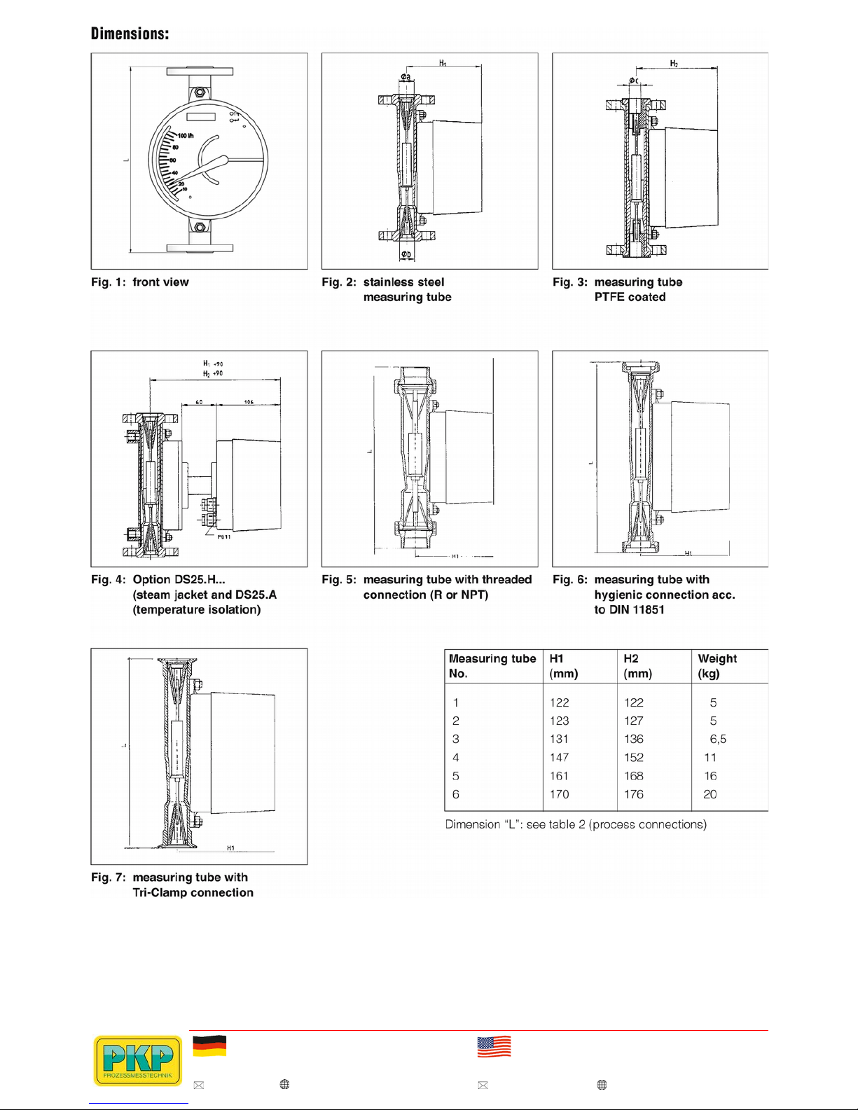
Flowmeter selection procedure:
1. Define materials of wetted parts
2. Select process connection
(table “process connections“)
3. Select measuring range
(table “measuring ranges”)
4. Select indicator and output signals
5. Select options
2. Process connections:
Nom.
pipe
size
[DN]
Process connection Meas.
tube
No.
Conn.
code
No.
Length
L [mm]
15
(1/2“)
flange DN 15 PN 40
flange ANSI 1/2“ 150 Ibs.
flange ANSI 1/2“ 300 Ibs.
G 1/2 female
1/2“ NPT female
flange DN 15 PN 40
flange ANSI 1/2" 150 lbs.
flange ANSI 1/2" 300 lbs.
1
1
1
1
1
2
2
2
101
102
103
104
105
206
207
208
250
250
250
295
295
250
250
250
20
(3/4“)
flange DN 20 PN 40
flange ANSI 3/4" 150 lbs.
flange ANSI 3/4" 300 lbs.
flange DN 20 PN 40
flange ANSI 3/4", 150 lbs.
flange ANSI 3/4", 300 lbs.
G 3/4 female
3/4" NPT female
1
1
1
2
2
2
2
2
111
112
113
216
217
218
219
220
250
250
250
250
250
250
250
250
25
(1“)
flange DN 25 PN 40
flange ANSI 1" 150 lbs.
flange ANSI 1" 300 lbs.
threaded spigot DN 25 PN 40 (female)
acc. to DIN 11851
Tri-clamp DN 25 / 1
flange DN 25 PN 40
flange ANSI 1" 150 lbs.
flange ANSI 1" 300 lbs.
threaded spigot DN 25 PN 40 (female)
acc. to DIN 11851
Tri-clamp DN 25 / 1
flange DN 25 PN 40
flange ANSI 1", 150 lbs.
flange ANSI 1", 300 lbs.
G 1 female
1" NPT female
1
1
1
1
1
2
2
2
2
2
3
3
3
2
2
121
122
123
126
127
228
229
230
233
234
335
336
337
338
339
250
250
250
275
250
250
250
250
275
250
250
250
250
250
250
Flange for nominal pipe size DN 125 / 5" and DN 150 / 6"
on request.
1. Material version (wetted parts):
The flow meters model DS25 may be supplied either completely
in stainless steel 1.4404 (DS25.1) or with PTFE- coating
(DS25.2).
Nom.
pipe
size
[DN]
Process connection Meas.
tube
No.
Conn.
code
No.
Length
L [mm]
32
(1 1/4“)
flange DN 32 PN 40
Tri-clamp DN 32
flange DN 32 PN 40
flange ANSI 1 1/4" 150 lbs.
flange ANSI 1 1/4" 300 lbs.
Tri-clamp DN 32
flange DN 32 PN 40
flange ANSI 1 1/4", 150 lbs.
flange ANSI 1 1/4", 300 lbs.
G 1 14 female
1 1/4" NPT female
1
1
2
2
2
2
3
3
3
3
3
140
141
242
243
244
245
346
347
348
349
350
250
250
250
250
250
250
250
250
250
250
250
40
(1 1/2“)
Tri-clamp DN 40 / 1 1/2"
Tri-clamp DN 40 / 1 1/2"
flange DN 40 PN 40
flange ANSI 1 1/2", 150 lbs.
flange ANSI 1 1/2" 300 lbs.
G 1 1/2 female
1 1/2" NPT female
1
2
3
3
3
3
3
151
252
353
354
355
364
365
250
250
250
250
250
250
250
50
(2“)
flange DN 50 PN 40
flange ANSI 2" 150 lbs.
flange ANSI 2" 300 lbs.
threaded spigot DN 50 PN 25 (female)
acc. to DIN 11851
Tri-clamp DN 50 / 2"
flange DN 50 PN 40
flange ANSI 2" 150 lbs.
flange ANSI 2" 300 lbs.
flange DN 65 PN 40
flange ANSI 2 1/2" 150 lbs.
flange ANSI 2 1/2" 300 lbs.
3
3
3
3
3
4
4
4
4
4
4
356
357
358
359
360
461
462
463
469
470
471
250
250
250
275
250
250
250
250
250
250
250
65
(2 1/2“)
threaded spigot DN 65 PN 25 (female)
acc. to DIN 11851
G 2 1/2 female
2 1/2" NPT female
4
4
4
466
467
468
275
250
250
80
(3“)
threaded spigot DN 80 PN 25 (female)
acc. to DIN 11851
Tri-clamp DN 80 / 3"
flange DN 80 PN 40
flange ANSI 3", 150 lbs.
flange ANSI 3", 300 lbs.
4
4
5
5
5
469
470
571
572
573
275
300
250
250
250
100
(4“)
threaded spigot DN 100 PN 25
(female)
acc. to DIN 11851
Tri-clamp DN 100 / 4"
flange DN 100 PN 16
flange DN 100 PN 40
flange ANSI 4", 150 lbs.
5
5
6
6
6
574
575
676
677
678
300
250
250
250
250
Higher pressures on request
PKP Prozessmesstechnik GmbH
Borsigstr. 24 • D-65205 Wiesbaden
S +49 (0) 6122-7055-0 • +49 (0) 6122 7055-50
info@pkp.de • www.pkp.de
PKP Process Instruments Inc.
10 Brent Drive • Hudson, MA 01749
S +1-978-212-0006 • +1-978-568-0060
info@pkp-usa.com • www.pkp-usa.com

3. Measuring ranges:
Reference conditions: Water: 20 °C
3a) DS25.1. Stainless steel version Air: 0 °C, 1,013 bar abs.
Meas.
tube
Nr.
Meas.range-
code
Water/ Liquids Air/ Gases
Meas. range*
[m³/h]
Meas.-cone
No.
Float
No.
Pressure
drop
[mbar]
Meas. range*
[Nm³/h]
Meas. cone
No.
Float
No.
Pressure
drop
[mbar]
1 101 0,0025- 0,026
43 S0 40
0,075- 0,75
43 S0 45
102 0,004- 0,04 44 S0 40 0,12- 1,2 44 S0 45
103 0,0063- 0,063
47 S0 40
0,18- 1,8
47 S0 45
104 0,01- 0,1 51 S0 40 0,3- 3 51 S0 45
105 0,01- 0,1
53 L1 6
-
- - -
2 206 0,01- 0,1 53 L1 6 0,55- 5,5 53 M1 20
207 0,016- 0,16
53 M1 15
0,4- 4
53 L1 11
208 0,016- 0,16 54 L1 6 0,65- 6,5 54 L1 11
209 0,025- 0,25
53 S1 40
0,75- 7,5
53 S1 45
210 0,025- 0,25 57 L1 6 1- 10 57 L1 11
211 0,04- 0,4
54 S1 40
1,3- 13
54 S1 45
212 0,04- 0,4 61 L1 6 1,6- 16 61 L1 11
213 0,063- 0,63
57 S1 40
2- 20
57 S1 45
214 0,063- 0,63 61 M1 15 2,5- 25 62 L1 11
215 0,1- 1
61 S1 40
3- 30
61 S1 45
216 0,1- 1 62 M1 15 3,5- 35 62 M1 20
217 0,16- 1,6
62 S1 40
-
- - -
218 0,23- 2,3 62 V1 45 - - - -
3 319 0,1- 1
63 L2 7
4- 40
63 L2 12
320 0,16- 1,6 64 L2 7 5- 50 63 M2 22
321 0,25- 2,5
63 S2 41
7- 70
64 L2 12
322 0,25- 2,5 64 M2 16 9- 90 64 M2 22
323 0,4- 4
64 S2 41
13- 130
64 S2 47
324 0,6- 6 64 V2 43 - - - -
4 425 0,25- 2,5
67 L5 8
10- 100
67 L5 14
426 0,4- 4 71 L5 8 13- 130 67 M5 25
427 0,63- 6,3
67 S5 47
16- 160
71 L5 14
428 0,63- 6,3 72 L5 8 20- 200 71 M5 25
429 1- 10
71 S5 47
20- 200
67 S5 54
430 1- 10 72 M5 19 28- 280 72 L5 14
431 1,6- 16
72 S5 47
36- 360
72 M5 25
432 2,3- 23 72 V5 63 50- 500 72 S5 54
5 533 2,5- 25
73 V8 60
50- 500
73 L8 30
534 4- 40 74 V8 60 75- 750 73 V8 65
535 6,3- 63
77 V8 60
85- 850
74 L8 30
536 - - - - 120- 1200 74 V8 65
537 -
- - -
180- 1800
77 V8 65
6 638 10- 100 81 11 70 - - - -
639 15- 130
81 12 -
-
- - -
Measuring range for steam on request
* The specified measuring ranges - in particular for air - serve for orientation.
Please specify the following process conditions for inquiries:
Medium, pressure, temperature
We create an individual scale for you at no extra charge.
PKP Prozessmesstechnik GmbH
Borsigstr. 24 • D-65205 Wiesbaden
S +49 (0) 6122-7055-0 • +49 (0) 6122 7055-50
info@pkp.de • www.pkp.de
PKP Process Instruments Inc.
10 Brent Drive • Hudson, MA 01749
S +1-978-212-0006 • +1-978-568-0060
info@pkp-usa.com • www.pkp-usa.com

3b) DS25.2 – Wetted parts PTFE coated
Meas.
tube
No.
Meas.range-
code
Water/ Liquids Air/ Gases
Meas. range*
[m³/h]
Meas.-
cone
No.
Float
No.
Pressure
drop
[mbar]
Meas. range*
[Nm³/h]
Meas.-
cone
No.
Float
No.
Pressure
drop
[mbar]
2 250 0,01 – 0,1 51 A1 16 0,35- 3,5 51 A1 20
251 0,016- 0,16 52 A1 16 0,5- 5 52 A1 20
252 0,025- 0,25 53 A1 16 0,85- 8,5 53 A1 20
253 0,04- 0,4 54 A1 16 1,3- 13 54 A1 20
254 0,063- 0,63 57 A1 16 2- 20 57 A1 20
255 0,1- 1 61 V1 18 3,4- 34 61 V1 22
3 356 0,16- 1,6 62 A2 20 5- 50 62 A2 25
357 0,25- 2,5 63 A2 20 8,5- 85 63 A2 25
358 0,4- 4 63 V2 22 - - - -
4 459 0,4- 4 64 A5 20 13- 130 64 A5 25
460 0,63- 6,3 67 A5 20 20- 200 67 A5 25
461 1- 10 71 A5 20 35- 350 71 A5 25
462 1,6- 16 71 V5 22 - - - -
5 563 1,6- 16 72 V8 25 50- 500 72 27 12
564 2,5- 25 73 V8 25 85- 850 73 27 22
565 4- 40 74 V8 25 - - - -
6 666 6,3- 63 77 10 30 - - - -
* The specified measuring ranges - in particular for air - serve for orientation.
Please specify the following process conditions for inquiries:
Medium, pressure, temperature
We create an individual scale for you at no extra charge.
Technical Data (Measuring tube):
Measured media: liquids, gases or steam
Measuring ranges: see tables 3a) and 3b)
Turndown ratio: 10:1
Accuracy:
DS25.1: class 1.6
DS25.2: class 2.5
Process connection: see table
„Process connection“
Max. pressure: see table
„Process connection“
Operating temperature:
DS25.1: −180 °C…370 °C
DS25.2: − 80 °C…130 °C
Note max. operating temperatures of the display part and any
options.
Materials:
DS25.1: all wetted parts stainless steel
1.4404, (AISI 316 L)
DS25.2: all wetted parts stainless steel
1.4404, (AISI 316 L) with PTFE
coating
Mounting: vertical
Flow direction: from bottom to top
Mounting length: see table „process connection“
Straight pipe runs:
DN 15-65 none
DN 80-100 min. 5D
protection class: IP66
PKP Prozessmesstechnik GmbH
Borsigstr. 24 • D-65205 Wiesbaden
S +49 (0) 6122-7055-0 • +49 (0) 6122 7055-50
info@pkp.de • www.pkp.de
PKP Process Instruments Inc.
10 Brent Drive • Hudson, MA 01749
S +1-978-212-0006 • +1-978-568-0060
info@pkp-usa.com • www.pkp-usa.com

4. Indicator:
The indicator part of the DS25 consists of an aluminium or
stainless steel housing with a pointer assembly magnetically
coupled to the float.
The scale may be calibrated in flow units or in percent.
Additionally, transducers and alarm contacts may be mounted in
the indicator housing.
4a. Housing versions
Material: Code No.
Aluminium, round, d = 160 mm
Stainless steel, round, d = 160 mm
2
3
4b. Alarm contacts
Contact version: Code No.
without
1 min.-contact
1 max.-contact
1 min.-contact + 1 max.-contact
2 Min.-contacts
2 Max.-contacts
0
1
2
3
4
5
4c. Analogue output signals
Type: Code No.
without
electrical transmitter
electrical transmitter (Ex)
0
1
2
4d. Power supply and output signals
Type: Code No.
without
115 VAC, 0…20 mA, 4-wire
115 VAC, 4…20 mA, 4-wire
230 VAC, 0…20 mA, 4-wire
230 VAC, 4…20 mA, 4-wire
24 VDC, 0…20 mA, 3-wire
24 VDC, 4…20 mA, 2-wire (standard)
24 VDC, 4…20 mA, 3-wire
24 VDC, 4...20 mA, 2- wire HART
®
9-32 VDC, PROFIBUS, 2-wire
00
01
02
03
04
07
08
09
10
11
Technical Data (Indicator Assembly):
Mechanical indicator assembly:
Ambient
temperature:
-25 °C...130 °C, for higher or lower
operating temperature use option
“temperature isolation
Alarm contacts:
Type: inductive proximity switch SJ 3,5-N
acc. to DIN 19234 (NAMUR)
Ambient
temperature:
−25 °C …100 °C (for higher or lower
operating temperatures use option
“temperature insolation”)
Rated voltage: 8 VDC (Ri = 1 kOhm)
Output signal: ≤ 1 mA = 0
≥ 3 mA = 1
Explosion
protection:
EEx ia IIC T6,
group II category 2G (on request)
Dust- explosion
protection:
EEx iaD 20 T 108 °C,
group II category 1D
Recommended
accessories:
contact protection relay type
KFA/KFD (see chapter supplies)
Electrical transmitter:
Output signal:
0…20 mA, 4 - 20 mA
Display:
LCD, 8-digits, (programmable for
indication of flow rate or as non
resettable totalizer)
Power supply:
see table 4d
Max. Load:
4-wire: ≥ 500 Ohm
2/3-wire: (U-13,5 V) 20 mA
Operating
temperature: 0 °C…100 °C (for higher or lower
operating temperatures use option
“temperature insolation”)
Electrical
connection: M16 x 1,5 or 1/2" NPT
Intrinsically safe electronic transducer:
Technical Data as standard unit, but:
Output signal: 4…20 mA
Operating
temperature:
−25 °C…70 °C (for higher or lower
operating temperatures use option
“temperature insolation”)
Ex-protection: EEx nL IIC T6; protection „nL“;
group II; category 3G
EEx ia IIC T6 Gb; protection ia;
group II; category 2G
Dust explosion
protection:
EEx II 3D; group II; category 3D,
max: surface temperature: 80 °C
PKP Prozessmesstechnik GmbH
Borsigstr. 24 • D-65205 Wiesbaden
S +49 (0) 6122-7055-0 • +49 (0) 6122 7055-50
info@pkp.de • www.pkp.de
PKP Process Instruments Inc.
10 Brent Drive • Hudson, MA 01749
S +1-978-212-0006 • +1-978-568-0060
info@pkp-usa.com • www.pkp-usa.com

5. Options:
Temperature insolation IA:
For media temperatures outside the limits given in the technical
specifications for the indicator assembly the measuring tube and
the indicator assembly may be temperature isolated by mounting the indicator at a distance of 95 mm apart from the measuring tube. This ensures that the unit may be operated at media
temperatures as high as stated in the specifications for the
measuring tube.
Damping SD:
A float damping is recommended for gas applications to prevent
an up and down movement (only for DS25.1).
Heating H...:
Heating assemblies (steam jackets) are used to keep the
medium in the measuring tube at a required temperature. Steam
jackets are available with three different process connections:
H.1: DIN flanges DN 15 PN 40
H.2: DIN flanges DN 25 PN 40
H.3: Threaded connection R 1/4”
Oil and grease free OF:
For use with oxygen the meters may be supplied oil- and
grease- free.
Certifications:
on request
Tags, customer specified scales:
Stainless steel tags with customer specified text are optionally
available
Order Code:
Order number: DS25.
Variable Area Flowmeter
1. 121. 1. 321. 1. 0. 104
Material version:
1 = stainless steel
2 = wetted parts PTFE-coated
Process connection:
101…678= process connection acc. to
table 2
999 = special connection
(please specify in plain text)
Medium:
1 = water / liquids
2 = air / gases
3 = steam
Measuring range:
101…666 = measuring range acc. to table 3a or 3b
999 = special range (please specify in plain text)
Housing version: (acc. to table 4a)
2 = aluminium, round, d = 160 mm
3 = stainless steel, round, d = 160 mm
Alarm contacts:
0…5 = contacts acc. to table 4b
Analogue output and power supply:
1st. digit:
0…3 = analogue output acc. to table 4c
2nd.–3rd. digit:
00…13 = power supply and output signal acc. to table 4d
Options: please specify in plain text
Ordering information:
for complete identification of the meter the following
information must be specified:
1. order no. acc. to table above
2. a. name of medium
b. temperature
c. pressure
d. viscosity (for liquids only)
e. density
3. for gases only: reference conditions
4. options:
a. model number acc. to section “Options”
b. additional customer specific information
PKP Prozessmesstechnik GmbH
Borsigstr. 24 • D-65205 Wiesbaden
S +49 (0) 6122-7055-0 • +49 (0) 6122 7055-50
info@pkp.de • www.pkp.de
PKP Process Instruments Inc.
10 Brent Drive • Hudson, MA 01749
S +1-978-212-0006 • +1-978-568-0060
info@pkp-usa.com • www.pkp-usa.com
PKP Prozessmesstechnik GmbH
Borsigstr. 24 • D-65205 Wiesbaden
S +49 (0) 6122-7055-0 • +49 (0) 6122 7055-50
info@pkp.de • www.pkp.de
PKP Process Instruments Inc.
10 Brent Drive • Hudson, MA 01749
S +1-978-212-0006 • +1-978-568-0060
info@pkp-usa.com • www.pkp-usa.com
PKP Prozessmesstechnik GmbH
Borsigstr. 24 • D-65205 Wiesbaden
S +49 (0) 6122-7055-0 • +49 (0) 6122 7055-50
info@pkp.de • www.pkp.de
PKP Process Instruments Inc.
10 Brent Drive • Hudson, MA 01749
S +1-978-212-0006 • +1-978-568-0060
info@pkp-usa.com • www.pkp-usa.com
 Loading...