


Instruction Manual
DS09
Angle Seat Variable Area Flow Meter
PKP Prozessmesstechnik GmbH
Borsigstraße 24
D-65205 Wiesbaden-Nordenstadt
Tel.: ++49-(0)6122-7055-0
Fax: ++49-(0)6122-7055-50
Email: info@pkp.de

Table of Contents
Safety Information................................................................................................................................2
Functional Description.........................................................................................................................3
Design...................................................................................................................................................4
Installation Information........................................................................................................................4
Installation............................................................................................................................................7
Initial startup.........................................................................................................................................7
Tightening torque.................................................................................................................................8
Electrical Connection...........................................................................................................................9
Contact protection measures...............................................................................................................11
Venting the valve................................................................................................................................13
Setting the switch point......................................................................................................................13
Checking / reading-off the flow..........................................................................................................14
Troubleshooting guide........................................................................................................................15
Safety Information
General Instructions
To ensure safe operation, the device should only be operated according to the specifications in the
instruction manual. The requisite Health & Safety regulations for a given application must also be
observed. This statement also applies to the use of accessories.
Every person who is commissioned with the initiation or operation of this device must have read
and understood the operating instructions and in particular the safety instructions!
The liability of the manufacturer expires in the event of damage due to improper use, nonobservance of this operating manual, use of insufficiently qualified personnel and unauthorized
modification of the device.
Proper Usage
Series DS09 angle seat variable flow meters are designed to measure and monitor continuous flow
rates of liquids and gases which do not attack the device materials. All other usage is regarded as
being improper and outside the scope of the device.
The series DS09 flow meter devices should not be deployed as the sole agents to prevent dangerous
conditions occurring in plant or machinery. Machinery and plant need to be designed in such a
manner that faulty conditions and malfunctions do not arise that could pose a safety risk for
operators.
DS09 Instruction manual 05/2018 page 2

Dangerous substances
For dangerous media such as e.g. Oxygen, Acetylene, flammable or toxic substances as well as
refrigeration systems, compressors, etc. must comply with the relevant regulations beyond the
general rules.
Qualified Personnel
The DS09 devices may only be installed by trained, qualified personnel who are able to mount the
devices correctly. Qualified personnel are persons, who are familiar with assembling, installation,
placing in service and operating these devices and who are suitably trained and qualified.
Inward Monitoring
Please check directly after delivery the device for any transport damages and deficiencies.
Additional with reference to the accompanying delivery note the number of parts must be checked.
Claims for replacement or goods which relate to transport damage can only be considered valid if
the delivery company is notified without delay.
Functional Description
DS09 flow monitors operate on the principle of the variable area flowmeter. The flow monitor is
installed into a pipe system and measures the flow rate of the medium flowing through the pipe
system.
A float inside the flow monitor is moved by the flowing medium. Together with the float, the flow
indicator inside the sight glass is moved. A magnetic field is generated by the magnets integrated in
the flow indicator. The position of the float is detected by the switch contact.
In addition to electrical control through the Reed-contact (switch contact), the current flow rate can
also be read-off on the measuring scale on the sight glass.
Applications for DS09 flow monitors are, for example, cooling circuits. The device monitors the
volume flow of the cooling media to ensure sufficient cooling. If the flow through the flow monitor
drops below the threshold preset by the operator, the switch contact switches (change-over contact)
or opens (normally open contact).
DS09 Instruction manual 05/2018 page 3

Design
1 Venting screw
2 Device housing
3 Spring
4 Sight glass with measuring scale
5 Flow indicator
6 Process connection
7 Switch contact with socket or connection
cable
8 Media inlet
9 Media outlet
10 Primary flow unit
Installation Information
• Do not use the flow monitor with quick-acting valves
• Do not use the flow monitor with solenoid valves
• Do not subject the flow monitor to vibrations
• Do not subject the flow monitor to pressure surges
• Do not use the flow monitor with media containing solids or abrasives
• Use the flow monitor only with media previously approved by the manufacturer
• Do not use the flow monitor as the sole monitoring device to prevent dangerous conditions
• Do not install the flow monitor as a load bearing part within a pipeline system
• The flow monitor with sight glass must be installed in such a way as to preclude damage to
the sight glass by outside force. If necessary, install an appropriate impact protection device.
• External magnetic fields will influence the switch contact. Keep sufficient distance to
magnetic fields (e.g. electric motors).
• Piping, process connections or supports made of ferromagnetic material influence the
magnetic field of the device. Keep a space of minimum 100mm to those materials (e.g.
steel).
• Ensure that there are no foreign particles in the device
• Ensure that the device is not soiled
• Do not use any medium containing solids
DS09 Instruction manual 05/2018 page 4

Installation position/direction of flow:
The flow monitor must only be installed in one of the positions displayed above. The medium must
flow in the direction of the arrow (from a low to a high scale value).
Measuring inaccuracy due to incorrect installation!
The measuring accuracy of the flow monitor is influenced by
its position within the pipe system.
Changes in cross-section, branchoffs or bends in the pipe
system impair measuring accuracy.
– Ensure that the unimpeded flow sections are maintained
– Never reduce the pipe diameter immediately before the
device
Unimpeded flow sections
An unimpeded flow section of 10xDN (rated width) must be
maintained before the device.
An unimpeded flow section of 5xDN (rated width) must be
maintained after the device.
DS09 Instruction manual 05/2018 page 5

Unimpeded outlet
If the pipe system ends at an unimpeded outlet, the flow monitor must not be installed directly in
front of the opening. The device must always be completely filled with media to ensure measuring
accuracy.
DS09 Instruction manual 05/2018 page 6

Installation
1. Place the threaded end of the device onto the thread of the connecting pipe
2. Fasten the adapter union of the pipeline with a suitable spanner (1). When doing so, lock the
process connection of the device in place to prevent slip, using a suitable spanner (2).
3. Keep turning in the adapter union (1) while holding the process connection of the device
locked (2) until the connection is tight.
4. Repeat these steps at the other end of the device.
Initial startup
The following steps must be taken before initial startup and any subsequent startup (e.g. after remo val and installation during maintenance).
• Make sure that the plant is operating vibration-free. Vibrations could destroy the device.
• Make sure that the medium is flowing continuously. Pulse-like staggered loads could destroy
the device.
• Completely fill the pipelines. Partial filling(s) may result in malfunctions and damage to the
device.
• Vent the pipeline. If there are air bubbles in the line during the measurement, this could result in damage to the device caused by hydraulic shock. This may cause malfunctions.
• Make sure that the plant is operating without cavitation. Cavitation may result in malfunctions and damage to the device.
DS09 Instruction manual 05/2018 page 7

Tightening torque
DS09 Instruction manual 05/2018 page 8

Electrical Connection
The electrical connection of the flow monitor is via the connector plug. The switch contacts employed in these devices are potential free and do not require a power source. Switch contacts and
flow monitor have been optimally harmonized. After replacement of a switch contact, the switch
point must be readjusted.
Attention: Prior to the electrical connection of the device, it must be ensured that the supply voltage
matches that required and the supply voltage is switched off.
Switch contact with connector in compliance with EN175301-803, form C
Switch position under no-flow condition:
Normally Open (NOC) Change Over (COC)
Pin assignment plug socket (the ground-pin is not used)
Normally Open (NOC) Change Over (COC)
DS09 Instruction manual 05/2018 page 9

Switch contact, plug connector M12x1
Switch position under no-flow condition:
Normally Open (NOC) Change Over (COC)
Pin assignment M12x1 plug connection
Grounding the device
When installing the device in a pipe system, ensure that the device is grounded to the pipe system to
avoid a dangerous electrical potential difference.
DS09 Instruction manual 05/2018 page 10

Contact protection measures
Reed switches are basically designed for small contact ratings. To connect a load with higher power
consumption it is indispensable to use a contact protection relay (e.g. our series MSR01)
If you connect directly a load to a Reed contact the following recommendations should be considered.
None of the contact rating values printed on the switching unit must not to be exceeded, even momentarily. This is valid for each of the given values individually: voltage, current, power. The Reed
contact integrated in the switching unit is very sensible to electrical overload
Danger of overload is given by the following applications:
• inductive load
• capacitive load
• lamp load
Inductive Load
Inductive loads consist e.g. of relay, contactors, solenoid valves, motors, electric engines, etc.
WARNING: Voltage spikes at shut down (up to 10 times of nominal voltage)
Protective measures: (examples)
(Flyback diode, e.g. type 1N4007)
Capacitive Load
Capacitive loads consist e.g. of long connection cables or capacitive consumers.
WARNING: High current spikes at switching on (this will exceed the nominal current)
Protective measures: (examples)
Limitation of current by a resistor
Lamp Load
Lamp loads consist e.g. by light bulbs, starting motors .
WARNING: High current spikes at switching on, because the glowing spiral has low resistance
at low temperature.
Protective measures: (examples)
Limitation of current by a resistor or
preheating of the glowing spiral.
DS09 Instruction manual 05/2018 page 11

Connecting to a PLC
There is no need for protective measures by connecting the Reed switch to a PLC. The Reed contacts are plated by Tunsten, Gold, and Rhodium located in a protective atmosphere. They can be directly connected to the input terminals of a PLC without problems.
RC-Circuits as protective measures (Boucherot cell, Snubber)
In practice the following values of resistor/capacitor cells give good results. Nevertheless, the values
given in the following tables are only recommendations for general purposes. But it cannot be guaranteed that for specific applications more adequate Boucherot cells may exist.
For Reed switches of 10 – 40 VA
Voltage [V] Resistance [Ohm] Capacitance [nF]
230 1500 330
115 470 330
48 220 330
24 100 330
For Reed switches of 40 – 100 VA
Voltage [V] Resistance [Ohm] Capacitance [nF]
230 1000 330
115 470 330
48 100 330
24 47 330
DS09 Instruction manual 05/2018 page 12
Venting the valve
If air bubbles are present in the piping system during the measurement, the pipeline must be vented.
WARNING!
Risk of injury from uncontrolled release of media! If the threaded pin is opened too far, the media
will escape uncontrolled.
1. Using a hex screwdriver, loosen the threaded
pin 3 turns.
The air bubbles in the pipe system escape.
2. Tighten the threded pin, observing the correct
tightening torque for the threaded pin
Threaded pin for venting
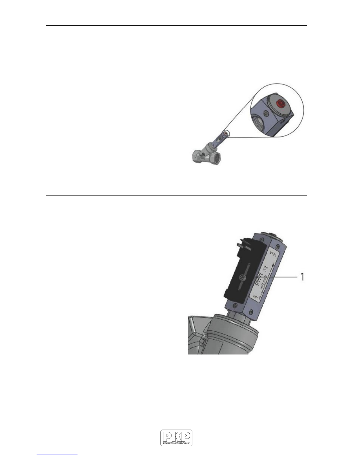
Setting the switch point
The following instructions describe the procedure for a Normally Open Contact (NOC). The actual
state (open or closed), can be determined using a continuity meter.
1. Loosen the set screw of the switch contact
(1) using a hex screwdriver.
2. Slide the switch contact to the point that corresponds to the flow rate to be monitored.
Ensure that the positioning arrow on the
switch contact adhesive label is aligned with
the desired flow rate on the switch point adjustment scale.
3. Tighten the set screw of the switch contact,
using a hex screwdriver. When doing so, observe the correct tightening torque of the
screw.
The set switch point corresponds to the switch-off
point of the switch contact by decreasing flow.
DS09 Instruction manual 05/2018 page 13
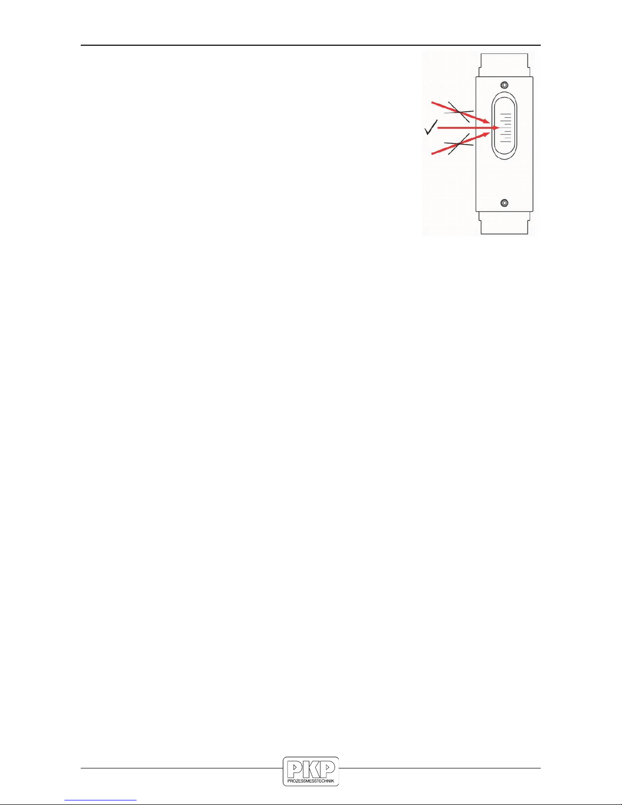
Checking / reading-off the flow
1. The top edge of the float is the read-off point
2. To obtain greatest reading accuracy, read-off at eye level. The
readoff value can be falsified by viewing at an angle
3. Read-off the flow value from the measuring scale
DS09 Instruction manual 05/2018 page 14

Troubleshooting guide
DS09 Instruction manual 05/2018 page 15

DS09 Instruction manual 05/2018 page 16

Flow Measurement and Monitoring
DS09
Angle Seat Variable Area Flow Meter
• high measuring range spans:
2,5...25 l/min and 10...100 l/min
• can be replaced without complete dismantling
due to angled seat
• any mounting position without recalibration
• compact design even for high flow rates
• high switching accuracy
• made of brass (nickel plated)
• analogue transmitter 4...20 mA available
Description:
The flowmeter and switch model DS09 works according to a
modified variable area principle. The float is guided by the
flowing medium into an angled seat measuring chamber.
Together with the float, the flow indicator, in which a magnet is
integrated, is also moved.
A reed contact or an analogue transmitter can be mounted
outside the device. The reed contact is encapsulated in a
continuously adjustable housing and thus protected from
external influences.
When the float reaches the position of the Reed contact the
switch will close. With higher flows the float moves further
upward until it reaches a built-in float stop, still keeping the
switch closed. This ensures a bistable switch function at any
time. The Reed contact is adjustable over the full switching
range of the meter.
Mounting position and functional reliability:
The device can be used in any mounting position by installing
a spring which pushes the float back into its initial position
against the flow.
The spring force and magnetic float guarantee absolute functional reliability.
Due to the angled seat of the measuring chamber, the device
can be removed for maintenance work without complete
removal. In addition, the angled seat ensures a large flow rate
in a small space.
Typical application:
The DS09 variable area flowmeters and monitors are used to
measure and monitor low-viscosity liquids in the following
areas:
Cooling systems, mechanical engineering, medical technology, research and development
PKP Prozessmesstechnik GmbH
Borsigstr. 24 • D-65205 Wiesbaden
S +49 (0) 6122-7055-0 • T +49 (0) 6122 7055-50
info@pkp.de • www.pkp.de
PKP Process Instruments Inc.
10 Brent Drive • Hudson, MA 01749
S +1-978-212-0006 • T +1-978-568-0060
info@pkp-usa.com • www.pkp-usa.com
181011

Models:
Connection / measuring range:
G ½ female, 2,5...25 l/min water
G 1 female, 10...100 l/min water
(referenced to 1,013 bar abs, 20 °C, medium density
1,0 kg/dm³, vertical installation, flow from button to top)
Technical Data:
Max. pressure: 10 bar
Pressure loss: ca. 0,3 bar
Max. media
temperature: 100 °C
160 °C (high temperature model optional)
Operating temp.: 70 °C with analogue transmitter SU20
Accuracy: ± 10 % of FS
(referenced to 1,013 bar abs, 20 °C,
density 1,0 kg/dm³,
vertical mounting,
flow from button to top)
Electr. connection: angle plug acc. to EN 175301-803,
form C (DIN 43650)
round plug M12 x 1 acc. to EN 50044,
optional: angle plug with LED or glow lamp
(on request)
Protection class: IP65
Materials:
Protective housing:
(non-wetted parts) aluminium anodized
Wetted parts:
Float: PEEK (DS09.15)
brass (DS09.25)
Spring: stainless steel 1.4571
Sight glass: borosilicate glass
Gaskets: NBR, optional FKM, EPDM
Magnet: ferrite
all other wetted parts: brass, nickel plated
Order Code:
Order Code: DS09.
Angle seat variable area flow meter
15. 1. 1. C. 0
Connection / Measuring range:
15 = G ½ female, 2,5...25 l/min water
25 = G 1 female, 10...100 l/min water
Material:
1 = brass nickel plated
Contact function / Analogue output:
(contact or analogue transmitter available)
0 = without
1 = 1 N/O
2 = 1 SPDT
SU20 = analogue transmitter 4...20 mA and 0...10 V
Electrical connection:
0 = without
C = angle plug DIN 43650, Form C
(not with analogue transmitter)
M12 = round plug M12 x 1
Options:
0 = without
1 = please specify in plain text
HT = high temperature version 160 °C (not with M12 plug)
Contacts:
The contact opens/changes, if the flow level has fallen under the
adjusted value
Switching capacity:
Contact
function
Angle plug M12x1 plug
1 = N/O
140 VAC, 0,7 A, 20 VA
200 VDC, 1 A, 20 VA
125 VAC, 0,7 A, 20 VA
125 VDC, 1 A, 20 VA
2 = SPDT
150 VAC/DC, 1 A, 20 VA 125 VAC/DC, 1 A, 20 VA
PKP Prozessmesstechnik GmbH
Borsigstr. 24 • D-65205 Wiesbaden
S +49 (0) 6122-7055-0 • T +49 (0) 6122 7055-50
info@pkp.de • www.pkp.de
PKP Process Instruments Inc.
10 Brent Drive • Hudson, MA 01749
S +1-978-212-0006 • T +1-978-568-006
info@pkp-usa.com • www.pkp-usa.com
Flow

Dimensions:
Dimension table:
Type Dimensions [mm] Weight
SW L1 L2 L3 T B [g]
DS09.15
DS09.25
27416590117
137
101
12214195050
300
700
PKP Prozessmesstechnik GmbH
Borsigstr. 24 • D-65205 Wiesbaden
S +49 (0) 6122-7055-0 • T +49 (0) 6122 7055-50
info@pkp.de • www.pkp.de
PKP Process Instruments Inc.
10 Brent Drive • Hudson, MA 01749
S +1-978-212-0006 • T +1-978-568-006
info@pkp-usa.com • www.pkp-usa.com

Analogue transmitter SU20:
• analogue signal 4...20 mA and 0...10 V
• operating temperature up to 70 °C
• accuracy: +/- 10 % of full scale
• aluminium housing, anodized
Technical Data:
Accuracy*: +/- 10 % of full scale
Operating temperature: -20…+70 °C
Storage temperature: -20...+80 °C
Repeatability: +/- 3 % of full scale
Material housing: aluminium, blue anodized
Protection class: IP67
* Higher calibration accuracy when calibrated individually. Available on
request.
Electrical Data:
Analogue output: 4...20 mA and 0...10 V
Power supply: 24 VCD (19...30 VDC)
Power consumption: < 1 W
Current output: Max. load 600 Ω
Voltage output: Max. current 10 mA
Connection: For round plug M12x1, 5 pin
Note:
Please note that the flowmeter and the analogue transmitter
have been optimally adjusted to each other and may not be
exchanged!
Electrical connection:
Dimensions:
Accessories (see separate data sheets):
• Needle valves SNV01, SNV02
• Ball valves SKG01, SKG02
• Dirt traps SF00, SF01
• Protection relay MSR01
• M12 Plug connector PVC-cable SM12
Notes:
The specified measuring/switching ranges apply when the
instrument is installed vertically and the flow rate is from bottom
to top.
Other installation positions or operating densities deviating from
the specified specifications increase the specified measuring
error.
Special scales for different media and operating conditions are
available on request.
The specified switching points are shut-off points at falling flow
rates. Please note that the switch-on points are higher due to
the hysteresis.
For applications where pressure surges are to be expected,
please contact PKP!
PKP Prozessmesstechnik GmbH
Borsigstr. 24 • D-65205 Wiesbaden
S +49 (0) 6122-7055-0 • T +49 (0) 6122 7055-50
info@pkp.de • www.pkp.de
PKP Process Instruments Inc.
10 Brent Drive • Hudson, MA 01749
S +1-978-212-0006 • T +1-978-568-006
info@pkp-usa.com • www.pkp-usa.com
 Loading...