

Page 1
3
SR B series coded magnetic safety sensors
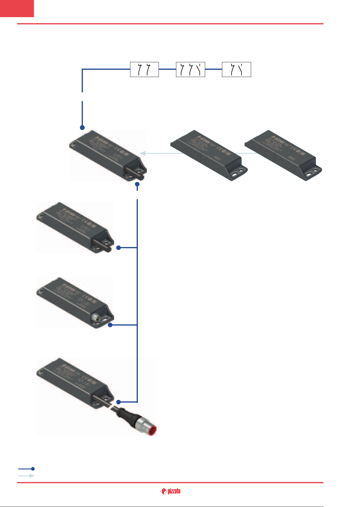
Selection diagram
CONTACTS
40 41 42
2NC 2NC+1NO 1NC+1NO
Contact states are displayed for closed guard
SENSOR
SR BD••AN•
PVC cable
OUTPUT TYPE
ACTUATOR
SM B01F SM B02F
Actuation distance 5 mm Actuation distance 8 mm
25
SR BD••ALK
Integrated M8 connector
SR BD••AM0.1
Cable, length: 0.1 m,
with M12 connector
product option
accessory sold separately
General Catalogue Safety 2017-2018
Page 2
Attention! The feasibility of a code number does not mean the effective availability of a product. Please contact our sales office.
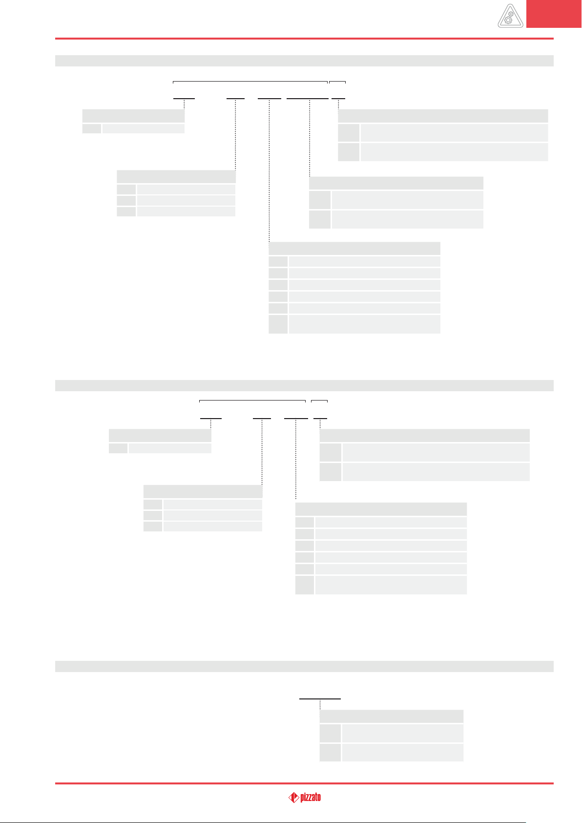
Code structure for sensor with actuator
SR BD40AN2-B01F-X
article
3
options
Sensor housing
SR
technopolymer
Contacts (with closed guard)
40
2NC (standard)
41
2NC+1NO (standard)
42
1NC+1NO
Code structure for single sensor
External metallic parts
stainless steel fixing plates (standard)
fixing plates and connector body in stainless steel
X
(LK connector available only)
Actuator
complete with actuator SM B01F, actuation
B01F
distance 5 mm
complete with actuator SM B02F, actuation
B02F
distance 8 mm
Cable or connector type
N1
PVC cable, length: 1 m
N2
PVC cable, length: 2 m (standard)
…
…………………………….
N10
PVC cable, length: 10 m
M0.1
cable, length: 0.1 m, with M12 connector
integrated M8 connector
LK
(available only with contacts 40 and 42)
Attention! The feasibility of a code number does not mean the effective availability of a product. Please contact our sales office.
article
options
SR BD40AN2-X
Sensor housing
SR
technopolymer
Contacts (with closed guard)
40
2NC (standard)
41
2NC+1NO (standard)
42
1NC+1NO
Code structure for single actuator
External metallic parts
stainless steel fixing plates (standard)
fixing plates and connector body in stainless steel
X
(LK connector available only)
Cable or connector type
N1
PVC cable, length: 1 m
N2
PVC cable, length: 2 m (standard)
…
…………………………….
N10
PVC cable, length: 10 m
M0.1
cable, length: 0.1 m, with M12 connector
integrated M8 connector
LK
(available only with contacts 40 and 42)
Attention! The feasibility of a code number does not mean the effective availability of a product. Please contact our sales office.
SM B01F
General Catalogue Safety 2017-2018
Actuator
B01F
actuation distance 5 mm
B02F
actuation distance 8 mm
26
Page 3
3
SR B series coded magnetic safety sensors
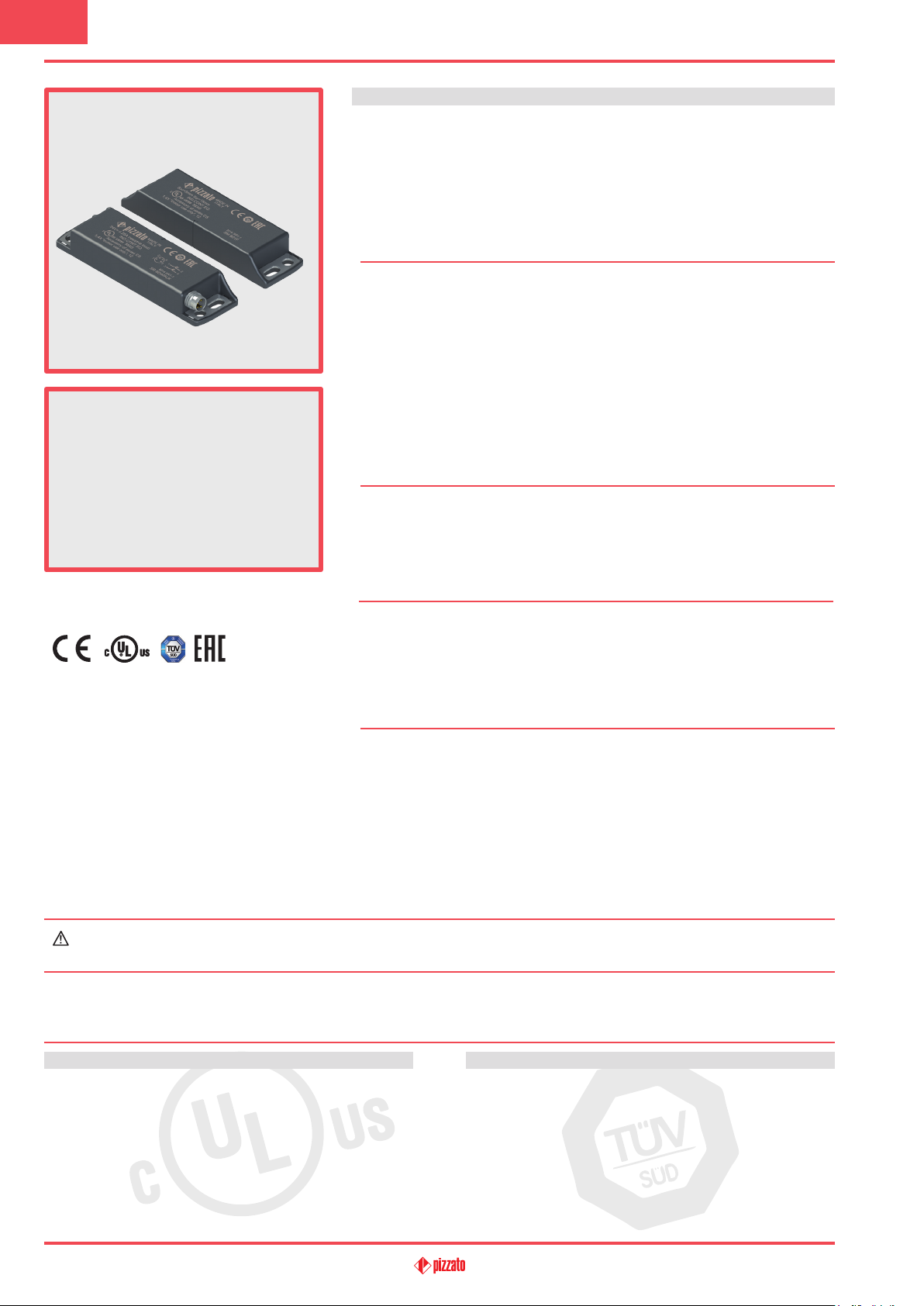
Main features
• Actuation without mechanical contact
• Stainless steel xing plates
• Output contacts: 2NC, 1NO+2NC or
1NO+1NC
• Insensitive to dirt
• Protection degrees IP67 and IP69K
• Coded actuator
• Technopolymer housing
• Versions with M8 or M12 connector
Quality marks:
UL approval: E496318
TÜV SÜD approval: Z10 15 08 75157 008
EAC approval: RUC-IT.AД35.В.00454
Compliance with the requirements of:
Low Voltage Directive 2014/35/EU
Machinery Directive 2006/42/EC
EMC Directive 2014/30/EU.
Technical data
Housing
Housing made of glass bre reinforced technopolymer, self-extinguishing.
Versions with integrated cable 4 x 0.34 mm
lengths from 0.5 m … 10 m on request.
Versions with integrated M8 connector
Versions with 0.1 m cable length and M12 connector, other lengths from 0.1 … 3 m
on request
Protection degree: IP67 acc. to EN 60529
General data
For safety applications up to: SIL 3 acc. to EN 62061
Interlock, no contact, coded: type 4 acc. to EN ISO 14119
Coding level: low acc. to EN ISO 14119
Safety parameter B
: 20,000,000 (with compatible Pizzato Elettrica safety
10D
Service life: 20 years
Ambient temperature: -25°C … +80°C
Ambient temp. with exible installation cable: -5°C … +80°C
Vibration resistance: 10 gn (10 … 150 Hz) acc. to IEC 60068-2-6
Shock resistance: 30 gn; 11 ms acc. to EN 60068-2-27
Pollution degree 3
Screw tightening torque: 0.8 … 2 Nm
In compliance with standards:
IEC 60947-1, EN 60947-1, IEC 60947-5-1, EN 60947-5-1, EN 60947-5-2, EN 60947-5-3
(in connection with safety module), EN ISO 14119, EN ISO 12100, EN ISO 13849-1,
EN ISO 13849-2, IEC 60204-1, EN 60204-1, IEC 60529, EN 60529, ISO 20653,
UL 508, CSA 22.2 No.14 .
Approvals:
UL 508, CSA 22.2 No.14 , EN ISO 13849-1, EN 60947-5-3, EN 50178, EN 61508-1,
EN 61508-2, EN 61508-4, IEC 62061, EN 60947-1.
Actuation data
Assured operating distance Sao 5 mm with actuator SM B01F
Assured release distance Sar 15 mm with actuator SM B01F
Assured operating distance Sao 8 mm with actuator SM B02F
Assured release distance Sar 20 mm with actuator SM B02F
Repeat accuracy ≤ 10%
Switching frequency up to 150 Hz
Distance between two sensors min. 50 mm
Electrical data
Rated operating voltage U
Rated operating current I
Rated insulation voltage Ui: 120 Vac (with cable)
: 24 Vac/dc
e
: 0.25 A (resistive load)
e
Rated impulse withstand voltage (U
Thermal current Ith: 0.25 A
Maximum switching load: 6 W
Protection fuse: 0.25 A type F
Electrical endurance: 1 million operating cycles
2
or 6 x 0.25 mm2, length 2 m, other
IP69K acc. to ISO 20653
(Protect the cables from direct high-pressure and
high-temperature jets)
PL e acc. to EN ISO 13849-1
modules)
400,000 (at max. load: DC12 24 V 250 mA)
60 Vac / 75 Vdc (with M8 connector)
120 Vac (with M12 connector, 4-pole)
30 Vac / 36 Vdc (with M12 connector, 8-pole)
): 6 kV
imp
1.5 kV
(with connector)
(resistive load)
If not expressly indicated in this chapter, for correct installation and utilization of all articles see chapter utilization requirements
from page 313 to page 324.
Connection with safety modules for safety applications:
Connection with safety modules CS AR-01••••; CS AR-02••••; CS AR-04••••; CS AR-05••••; CS AR-06••••; CS AR-08••••;
CS AR-46•024; CS AR-91••••; CS AT-0•••••; CS AT-1•••••; CS AT-3•••••; CS FS-5•••••; CS MF•••••-••; CS MP•••••-••.
When connected to the safety module, the sensor can be classied as a control circuit device up to PDF-M (EN 60947-5-3).
The system can be used in safety circuits up to PL e/SIL 3/category 4 in accordance with EN ISO 13849-1.
Features approved by UL
Utilization categories: 24 Vdc, 0.25 A (resistive load).
Housing features type 1, 4X “indoor use only”, 12.
Accessory for CS series.
In compliance with standard: UL 508, CSA 22.2 No.14
Please contact our technical department for the list of approved products.
27
Features approved by TÜV SÜD
Supply voltage: 24 Vac/dc
Rated operating current (max.): 0.25 A
Ambient temperature: -25 °C … + 80°C
Protection degree: IP67
PL, category: PL e, category 4 with CS AR-08
In compliance with standards: 2006/42/EEC Machine Directive,
EN ISO 13849-1:2008, EN 60947-5-3/A1:2005, EN 50178:1997,
EN 61508-1:1998 (SIL 1-3), EN 61508-2:2000 (SIL 1-3), EN 61508-4:1998
(SIL 1-3), IEC 62061:2005 (SIL CL 3), EN 60947-1
Please contact our technical department for the list of approved products.
General Catalogue Safety 2017-2018
Page 4
Description
3
Coded magnetic sensors are devices suitable for monitoring protections and guards of machines without inertia
which, when linked to a safety module, can create a system with safety category up to SIL 3 according to EN 62061,
up to PL e according to EN ISO 13849-1 and up to category 4 according to EN ISO 13849-1. These products consist
of a sensor that detects the magnetic field and which is connected to the machine structure and of a coded magnetic actuator, which is connected to the movable guard. When the sensor and actuator are approached (closed
guard), the sensor detects the actuator and actuates the electrical contacts. The sensor is designed to be activated
only by the correct coded actuator and not through a common magnet.
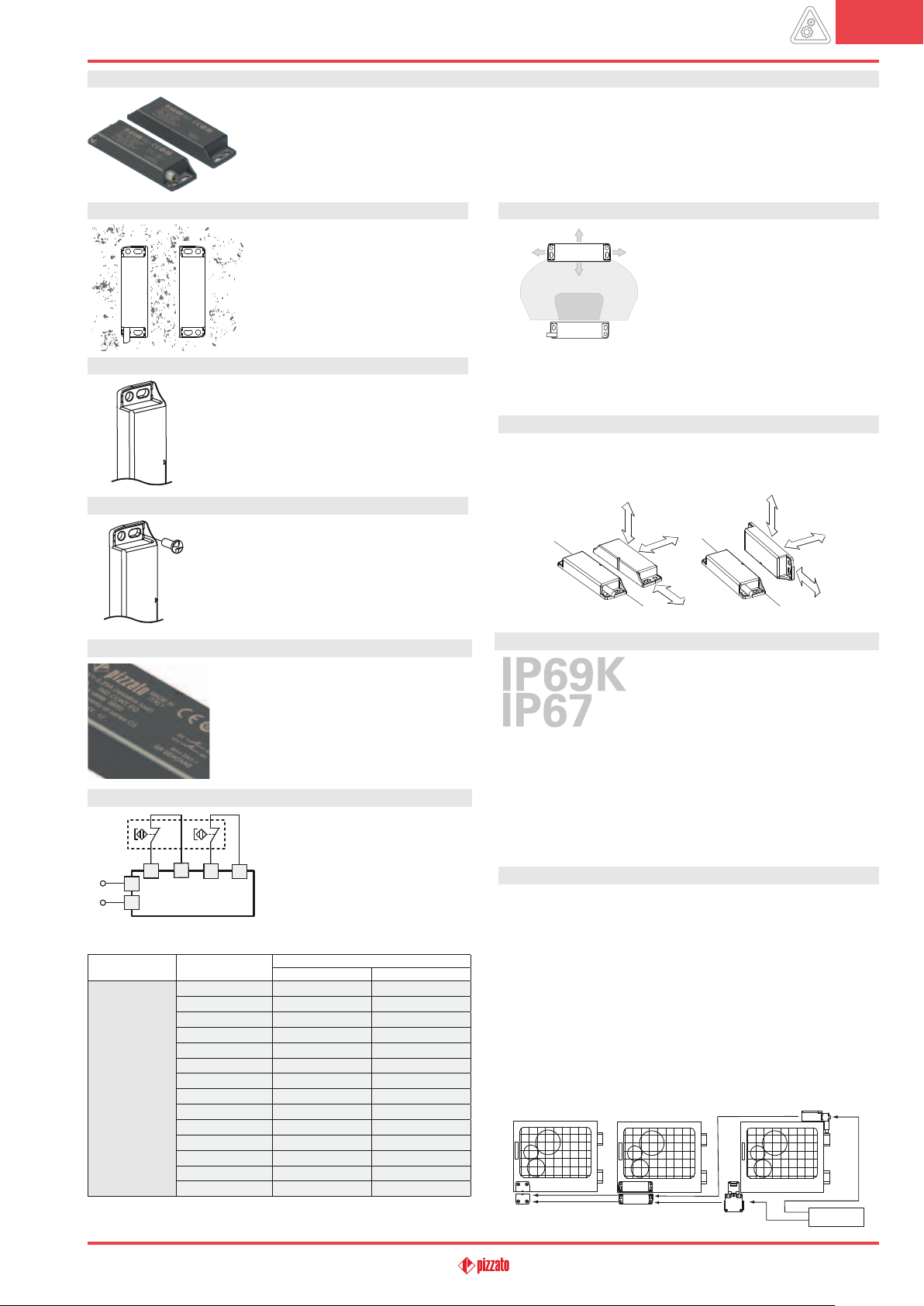
Insensitivity to dirt
Magnetic sensors are totally sealed
and retain their safety characteristics
also where dirt and dust are present
(not ferromagnetic material). This characteristic, combined with the design
without recesses, makes them particularly suitable for use in the agricultural
and food industries.
Stainless steel fixing plates
To prevent damage to the fixing slots when fastening on non-perfectly flat surfaces, coded magnetic sensors are equipped with stainless steel
fixing plates. Even in the presence of suitable
fixing surfaces, this solution makes the sensor
more robust against mechanical stresses.
Safety screws for actuators
As required by EN ISO 14119, the actuator must
be fixed immovably to the door frame. Pan head
safety screws with one-way fitting are available
for this purpose. With this screw type, the actuators cannot be removed or tampered by using
common tools.
See accessories on page 310.
Laser engraving
All devices are marked using a dedicated
indelible laser system. These engravings are
therefore suitable for extreme environments
too. Thanks to this system that does not use
labels, the loss of plate data is prevented and
a greater resistance of the marking is achieved
over time.
Compatible safety modules
SR BD40•••
L / +
N / -
Sensors
SR BD40A••
SR BD41A••
SR BD42A••
a
Compatible with CS MF202••-P4 and CS MP•••••-•• only.
b
Compatible with modules with production batch later than 04/2014 only.
For features of the safety modules see page 191.
Compatible safety
modules
CS AR-01••••b2NO+1NC /
CS AR-02••••
CS AR-04••••
CS AR-05•••• 3NO+1NC /
CS AR-06•••• 3NO+1NC /
CS AR-08•••• 2NO /
CS AR-46•024 1NO /
CS AR-91•••• 2NO+1PNP /
a
CS AT-0••••• 2NO+1NO 2NO
CS AT-1••••• 3NO 2NO
CS AT-3••••• 2NO 1NO
CS FS-5••••• 1NO+1NC+1CO /
CS MP•••••-•• see page 253 see page 255
CS MF•••••-•• see page 281 see page 283
b
b
The magnetic sensors have
been tested and approved for
operation with suitable safety
modules (see list). The use of
complete and tested solutions guarantees the electrical compatibility between the
sensor and safety module, as
well as high reliability.
Safety module output contacts
Instantaneous contacts
3NO /
3NO+1NC /
Delayed contacts
Wide actuation range
With their built-in features, magnetic
sensors have a wide actuation range,
making them very well suited for applications with large tolerances or where
mechanical properties change over
time.
In this type of sensor, the actuation
distances may vary depending on the
shift direction of the actuator in relation to the sensor.
Actuation from many directions
The coded magnetic sensors were designed to be activated by the
respective actuator from various directions. The customer therefore enjoys maximum flexibility when positioning devices along the
perimeter of the guards.
Protection degrees IP67 and IP69K
These devices are designed to be used in
the toughest environmental conditions and
they pass the IP67 immersion test acc. to
EN 60529. They can therefore be used in
all environments where maximum protec-
tion degree of the housing is required. Due
to their special design, these devices are suitable for use in equipment subjected to cleaning with high pressure hot water jets. These
devices meet the IP69K test requirements according to ISO 20653
(water jets with 100 bar and 80°C).
Series connection of multiple sensors
The coded magnetic sensors can be connected in series with the
only limitation that the overall resistance, of sensors and the related
wiring, has to be not higher than the admitted max. value of the
module, which typically is equal to 50 ohm (see module features).
This is a very high value that, with normal wiring, allows the use of
dozens of sensors without problems. It is also possible to realise
mixed circuit solutions by connecting coded magnetic sensors in
series to safety switches, with the only limitation being the abovementioned maximum electrical resistance.
It should be noted that the series connection of two or more coded
sensors reduces the self-monitoring capacity of the system, see
ISO/TR 24119.
The use of Pizzato Elettrica safety modules is recommended.
FR 1896-M2
SR AD40A••
FX 693-M2SR BD40A••
CS AR-08••••
General Catalogue Safety 2017-2018
28
Page 5
3
SR B series coded magnetic safety sensors
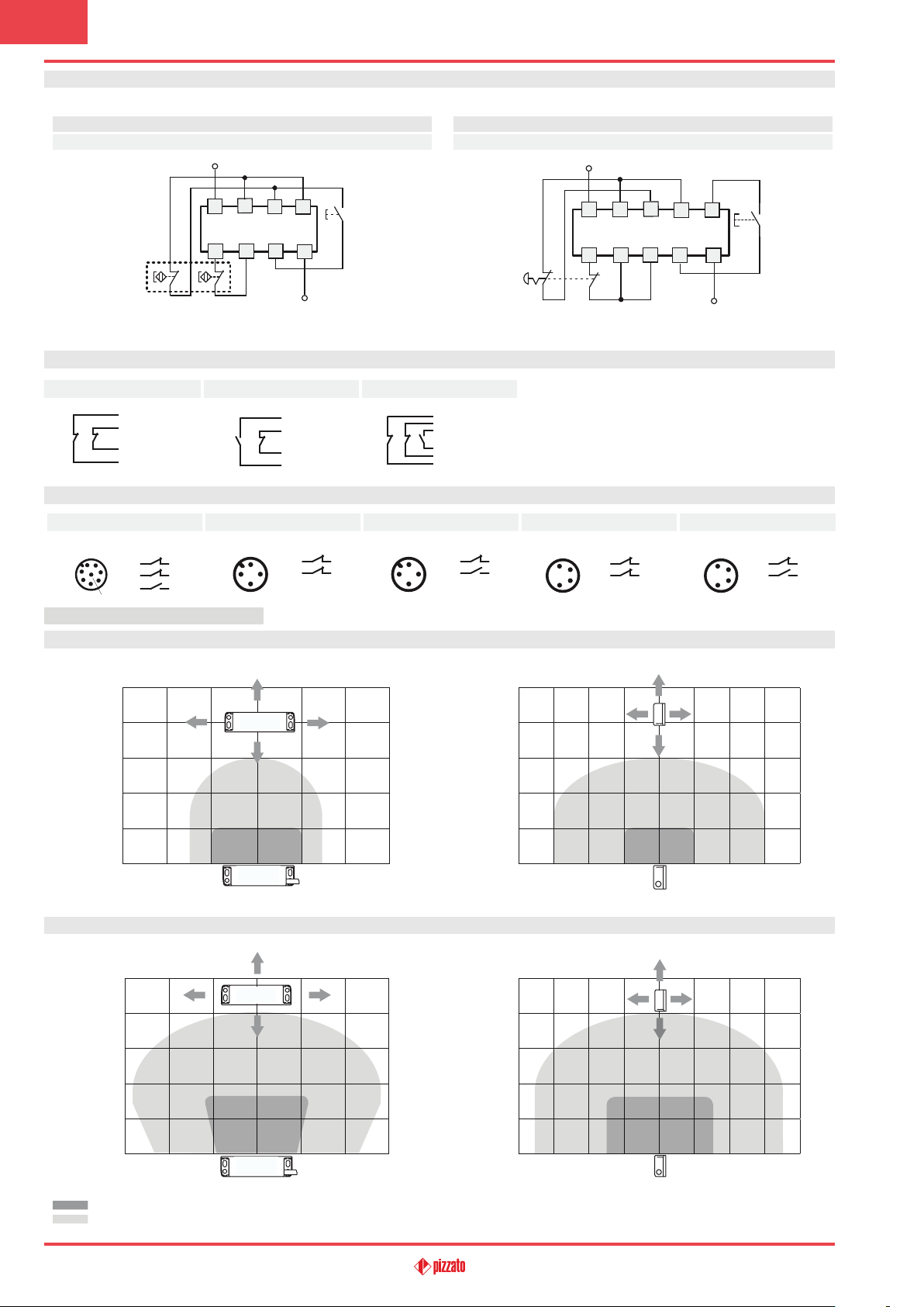
Connection with safety modules
Connection with safety modules CS AR-05 or CS AR-06 Connection with safety module CS AR-08 or CS AT
Input configuration with manual start (CS AR-05) and monitored start (CS AR-06)
2 channels
L / +
Input configuration with manual start
2 channels
L / +
SR BD40•••
S11
A1
CS AR-05 / CS AR-06
S21 S22
S12
S34
S52
S12
S11
A1
CS AR-08
A2
N / -
S21 S22
S35
S34
S31
S33
A2
N / -
For features of the safety modules see page 191.
Internal connections with cable
With cable (2NC) With cable (1NC+1NO) With cable (2NC+1NO)
Black
White
Brown
Blue
Black
White
Brown
Blue
Green
Brown
Grey
Pink
White
Yellow
Internal connections with connector
With M12 connector (2NC+1NO) With M12 connector (2NC) With M12 connector (1NC+1NO) With M8 connector (2NC) With M8 connector (1NC+1NO)
1
7
8
6
3 4
5 6
7 8
2
345
Female connectors see page 299
1
3
42
1 2
3 4
1
3
42
1 2
3 4
1
3
Contact states are displayed for closed guard
Contact states are displayed for closed guard
2
4
1 2
43
1
2
4
3
1 2
3
4
Operating distances SR BD•••••-B01F
(mm) 25
20
15
10
5
0 (mm)
-15 -10 -5 5 10 15
Operating distances SR BD•••••-B02F
(mm) 25
20
15
10
5
(mm) 25
20
15
10
5
0 (mm)
-20 -15 -10 -5 5 10 15 20
(mm) 25
20
15
10
5
0 (mm)
-15 -10 -5 0 5 10 15
Legend:
Assured operating distance S
Assured release distance S
Note: The progress of the activation areas is for reference only
ao
ar
29
0 (mm)
-20 -15 -10 -5 5 10 15 20
General Catalogue Safety 2017-2018
Page 6
3
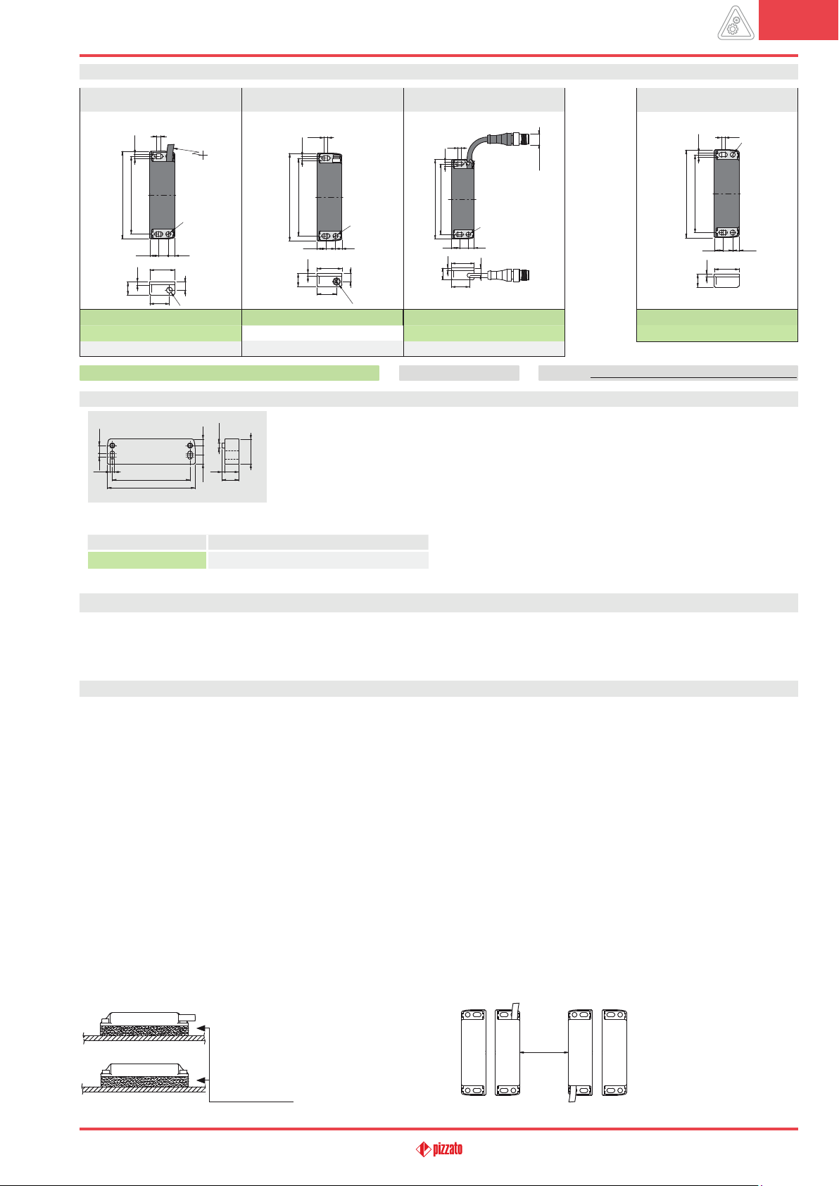
Dimensional drawings
integrated cable, length: 2 m M8 connector
3.8
4.5
R min.
88
78
88
5
6.59.68.9
25
2.9
8.1
13.1
19.7
SR BD40AN2
SR BD41AN2
SR BD42AN2
Items with code on green background are stock items
6
2NC
1NO+2NC
1NO+1NC
SR BD40ALK
SR BD42ALK
4.5
78
88
2.9
13.1
Spacer
This spacer is placed between the magnetic safety sensors and metal surfaces that can deflect the mag-
6.58.9
Ø 4.8
9.6
3.8 7.7
4.5
78
88
14
3
17
netic field: as a result, the activation and deactivation distances of the sensor remain the same.
25
All values in the drawings are in mm
cable, length: 0.1 m,
with M12 connector
3.8
5
6.59.68.9
25
8.6
M
19.7
8 x1
2NC
3.8
4.5
88
78
9.68.956.5
25
2.9
13
19.7
SR BD40AM0.1
8
SR BD41AM0.1
1NO+1NC
SR BD42AM0.1
Accessories See page 299
2NC
1NO+2NC
1NO+1NC
Low level of coding acc. to EN ISO 14119
M12x 1
SM B01F
SM B02F
The 2D and 3D les are available at www.pizzato.com
coded actuator
4.5
78
88
8.9
2.9
13
Actuation distance 5 mm
Actuation distance 8 mm
3.8
5
6.5
9.6
25
Article
VS SP1BA1
Description
Spacer for SR B series sensors
Use of coded magnetic sensors for safety applications
A coded magnetic sensor alone cannot be used for safety functions because its operating principles are not considered safe by the standards
(such as the positive opening on mechanical switches). For this reason, a magnetic sensor coded for use in safety applications must always be
connected to a safety module that monitors its proper operation through a circuit with at least two channels.
Limits of use
• Installation must be carried out by qualified staff only.
• Before commissioning and at regular intervals, the correct switching of the contacts and proper operation of the system, consisting of the
sensor and the safety module, must be checked.
• Do not use a hammer for adjustment.
• Do not use the sensor as a mechanical stop.
• Observe the assured operating and release distances.
• Adhere to the EN ISO 14119 requirements regarding low level of coding for interlocks.
• Do not mount the sensor and actuator in strong magnetic fields.
• Keep away from iron filings.
• Avoid any impact with the sensor. Excessive shock and vibrations may affect the correct operation of the sensor.
• The actuator must not strike the sensor.
• In case of damages or wear, the entire device – including the actuator – must be replaced.
• Keep load under the value indicated in the electrical data.
• If the sensors are used without corresponding safety module, the protective fuse recommended in the electrical data must be connected in
series to each sensor contact.
• Turn off the power supply before accessing the switch contacts, also during wiring.
Installation on ferromagnetic material
• If possible do not mount the sensor and
the actuator on ferromagnetic materials.
• To avoid a reduction in the switching
distances, use the special VS SP1BA1
spacer.
Spacer
General Catalogue Safety 2017-2018
Assembly of multiple sensor-actuator systems
The minimum spacing between
adjacent sensor-actuator sys-
50
tems must be at least 50 mm.
30
 Loading...