

Page 1
8
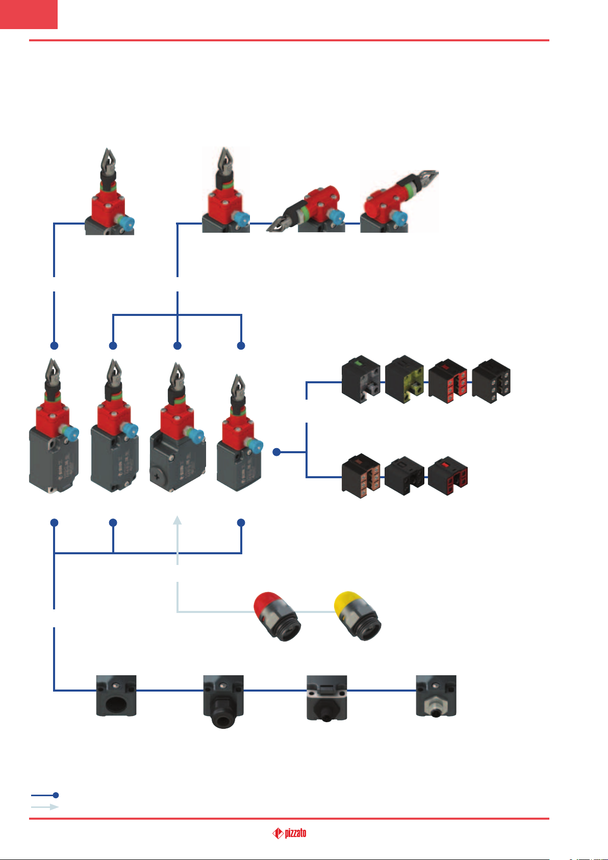
Safety rope switches with reset for emergency stop
Selection diagram
78
ACTUATORS ACTUATORS
FP FD FL FC
78 83 84
CONTACT
BLOCKS
18 9 20 21
1NO+1NC
slow action
2NO+1NC
slow action
slow action
22
1NO+1NC
slow action
2NC
1NO+2NC
slow action
33 34
slow action
3NC
slow action
2NC
CONDUIT ENTRIES
Threaded conduit entry
product option
accessory sold separately
169
LED SIGNALLING LIGHT
(standard)
With cable gland
Red Yellow
With M12 plastic
connector
For other available signal
lamps, see page 312
With M12 metal con-
nector
General Catalogue Safety 2017-2018
Page 2
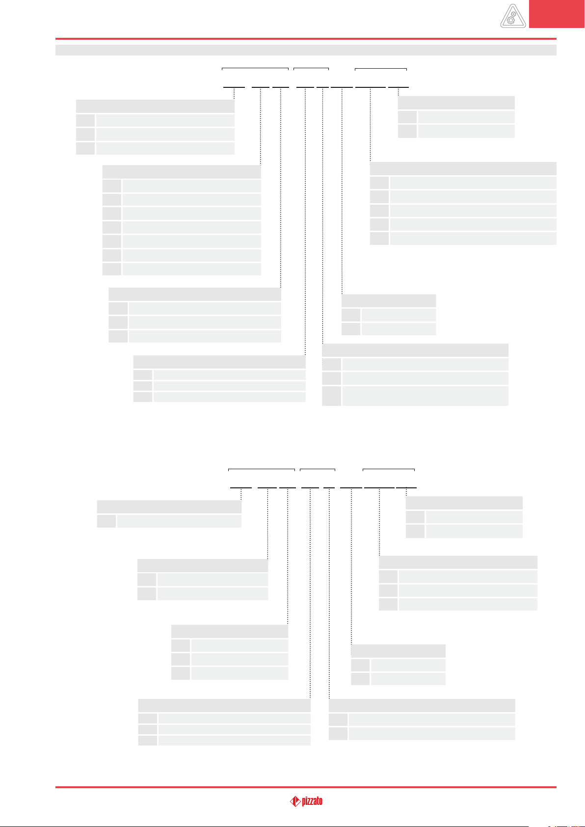
Code structure Attention! The feasibility of a code number does not mean the effective availability of a product. Please contact our sales office.
article options
options
FD 1878-E7GM2K50T6
8
Housing
FD
metal, one conduit entry
FL
metal, three conduit entries
FP
technopolymer, one conduit entry
Contact block
18
1NO+1NC, slow action
9
2NC, slow action
20
1NO+2NC, slow action
21
3NC, slow action
22
2NO+1NC, slow action
33
1NO+1NC, slow action
34
2NC, slow action
Actuating head
78
longitudinal head
83
left transversal head
84
right transversal head
Actuating force
standard
E7
initial 20 N...final 40 N
E9
initial 13 N...final 75 N
(FD-FL housing only)
(FD-FL housing only)
(only head 78)
(only head 83-84)
Ambient temperature
-25°C … +80°C (standard)
T6
-40°C … +80°C
Pre-installed cable glands or connectors
no cable gland or connector (standard)
K23
cable gland for cables Ø 6 … 12 mm
…
……………………
K50
M12 metal connector, 5-pole
…
……………………
For the complete list of possible combinations please contact our technical department.
Threaded conduit entry
M2
M20x1.5 (standard)
PG 13.5
Contact type
silver contacts (standard)
G
silver contacts with 1 µm gold coating
Silver contacts, 2.5 µm gold coating
G1
(not for contact blocks 20, 21, 22, 33, 34)
Housing
FC
metal, one conduit entry
Contact block
33
1NO+1NC, slow action
34
2NC, slow action
Actuating force
standard
E7
initial 20 N...final 40 N
E9
initial 13 N...final 75 N
Actuating head
78
longitudinal head
83
left transversal head
84
right transversal head
article options
options
FC 3378-E7GM2K50T6
Pre-installed cable glands or connectors
no cable gland (standard)
K23
cable gland for cables Ø 6 … 12 mm
K50
M12 metal connector, 5-pole
Threaded conduit entry
M2
M20x1.5 (standard)
PG 11
Contact type
(only head 78)
(only head 83-84)
silver contacts (standard)
G
silver contacts with 1 µm gold coating
Ambient temperature
-25°C … +80°C (standard)
T6
-40°C … +80°C
General Catalogue Safety 2017-2018
170
Page 3
8
Safety rope switches with reset for emergency stop
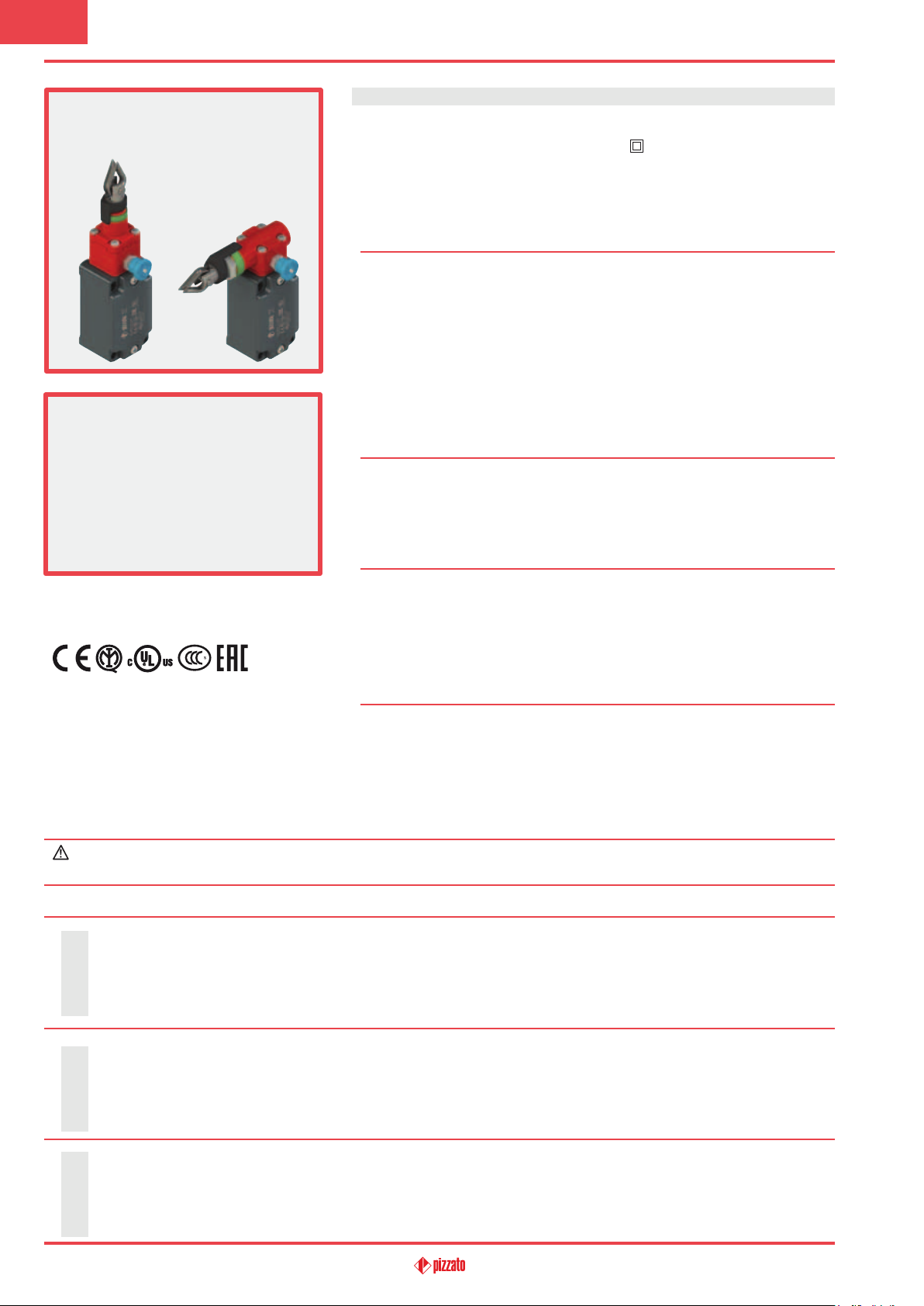
Main features
•Metal or plastic housing, from one to three
conduit entries
•Protection degree IP67
•In compliance with EN ISO 13850
•7 contact blocks available
•Versions with vertical or horizontal actuation
•Versions with assembled M12 connector
•Versions with gold-plated silver contacts
Technical data
Housing
FP series housing made of glass fibre reinforced technopolymer, self-extinguishing,
shock-proof and with double insulation:
FD, FL and FC series: metal housing, baked powder coating.
FD, FP, FC series: one threaded conduit entry: M20x1.5 (standard)
FL series: three threaded conduit entries: M20x1.5 (standard)
Protection degree: IP67 acc. to EN 60529 with cable
General data
For safety applications up to: SIL 3 acc. to EN 62061
Safety parameters:
: 2,000,000 for NC contacts
B
10D
Service life: 20 years
Ambient temperature: -25°C … +80°C
Max. actuation frequency: 1 cycle / 6 s
Mechanical endurance: 1 million operating cycles
Max. actuation speed: 0.5 m/s
Min. actuation speed: 1 mm/s
Tightening torques for installation: see page 313-324
Max. cable cross section (flexible copper strands)
Contact blocks
20, 21, 22, 33, 34: min. 1 x 0.34 mm2 (1 x AWG 22)
Contact blocks 18, 9: min. 1 x 0.5 mm2 (1 x AWG 20)
gland of equal or higher protection
degree
PL e acc. to EN ISO 13849-1
max. 2 x 1.5 mm
max. 2 x 2.5 mm
2
(2 x AWG 16)
2
(2 x AWG 14)
In compliance with standards:
IEC 60947-5-1, EN 60947-5-1, EN 60947-1, IEC 60204-1, EN 60204-1, EN ISO 14119,
EN ISO 12100, IEC 60529, EN 60529, EN ISO 13850, EN 418, UL 508, CSA 22.2
Quality marks:
No.14.
Approvals:
IEC 60947-5-1, UL 508, CSA 22.2 No.14 , GB14048.5-2001.
IMQ approval: EG605
UL approval: E131787
CCC approval: 2007010305230000
(FD-FL-FC series)
2007010305230014
(FP series)
Compliance with the requirements of:
Machinery Directive 2006/42/EC and EMC Directive 2004/122/EC.
Positive contact opening in conformity with standards:
IEC 60947-5-1, EN 60947-5-1.
EAC approval: RUC-IT.AД35.В.00454
If not expressly indicated in this chapter, for correct installation and utilization of all articles see chapter utilization requirements
from page 313 to page 324.
Electrical data Utilization category
Thermal current (I
Rated insulation voltage (U
Rated impulse withstand voltage (U
without
Conditional short circuit current: 1000 A acc. to EN 60947-5-1
connector
Protection against short circuits: type aM fuse 10 A 500 V
Pollution degree: 3
): 10 A
th
): 500 Vac 600 Vdc
i
): 6 kV
imp
400 Vac 500 Vdc
4 kV
(contact blocks 20, 21, 22, 33, 34)
(contact blocks 20, 21, 22, 33, 34)
Alternating current: AC15 (50÷60 Hz)
(V) 250 400 500
U
e
Ie (A) 6 4 1
Direct current: DC13
Ue (V) 24 125 250
Ie (A) 6 1.1 0.4
Alternating current: AC15 (50÷60 Hz)
U
Thermal current (I
Rated insulation voltage (U
Protection against short circuits: type gG fuse 4 A 500 V
4 and 5-pole
Pollution degree: 3
with M12 connector
): 4 A
th
): 250 Vac 300 Vdc
i
(V) 24 120 250
e
Ie (A) 4 4 4
Direct current: DC13
Ue (V) 24 125 250
Ie (A) 4 1.1 0.4
171
Thermal current (Ith): 2 A
Rated insulation voltage (U
8-pole
Protection against short circuits: type gG fuse 2 A 500 V
Pollution degree: 3
with M12 connector
): 30 Vac 36 Vdc
i
Alternating current: AC15 (50÷60 Hz)
Ue (V) 24
Ie (A) 2
Direct current: DC13
Ue (V) 24
Ie (A) 2
General Catalogue Safety 2017-2018
Page 4
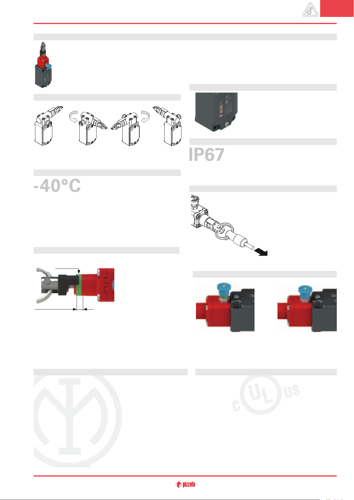
Description
These rope-operated safety switches are installed on machines or conveyor belts and allow the machine to be brought to an emergency stop from any point and with any pull on the rope. This means significant cost savings for medium and large machines, since
multiple emergency-stop buttons can be replaced with a single switch. They are equipped with a self-control function that constantly checks the correct function and signals a possible loosening or breaking of the rope through the opening of the contacts. These
safety switches keep the contacts open after activation until the reset is performed, even if the rope is released.
Head with variable orientation
For all switches, the head can be adjusted in 90° steps after removing
the four fastening screws.
Extended temperature range
These devices are also available in a special
version suitable for an ambient operating
temperature range from -40ºC up to +80°C.
They can therefore be used for applications in cold stores, sterilisers
and other equipment with low temperature environments. The special materials used to produce these versions retain their characteristics even under these conditions, thereby expanding the installation
possibilities.
Indicator for rope adjustment
Tension indicator
Area of correct rope
tightening
contacts.
If the tension (or loosening) on the rope is so high that the black
indicator exits the green area, the electrical safety contacts will open
and the reset device will trigger.
All switches are provided
with a green ring that shows
the area of the correct
tightening of the rope. The
installer has only to tighten
the rope until the black indicator will be in the middle of
the green area. With this setting, the switch can be reset
by pulling the blue knob to
close the electrical safety
Laser engraving
All devices are marked using a dedicated
indelible laser system. These engravings are
therefore suitable for extreme environments
too. Thanks to this system that does not use
labels, the loss of plate data is prevented and
a greater resistance of the marking is achieved over time.
Protection degree IP67
These devices are designed to be used in the toughest environmental conditions and they pass the
IP67 immersion test acc. to EN 60529. They can
therefore be used in all environments where maximum protection
degree of the housing is required.
Reduced actuating force
These switches can be supplied with reduced hardness
internal springs on request. The
force required to actuate the
switch can thereby be reduced
without changing the actuating
path of the electrical contacts.
This is particularly advantageous for smaller spans, but
must, however, always make
use of rope pulleys.
Indicator for the state of the reset
Armed reset
If the tension indicator is in the green area, the electrical safety contacts can be closed by pulling the blue knob. The reset status can be
identified quickly by the green ring under the blue knob.
Released
reset
8
Features approved by IMQ
Rated insulation voltage (Ui): 500 Vac
Conventional free air thermal current (Ith): 10 A
Protection against short circuits: type aM fuse 10 A 500 V
Rated impulse withstand voltage (Uimp): 6 kV
Protection degree of the housing: IP67
MV terminals (screw terminals)
Pollution degree: 3
Utilization category: AC15
Operating voltage (Ue): 400 Vac (50 Hz)
Operating current (Ie): 3 A
Forms of the contact element: Zb, Y+Y, Y+Y+X, Y+Y+Y, Y+X+X
Positive opening contacts on contact blocks 18, 9, 20, 21, 22, 33, 34
In compliance with standards: EN 60947-1, EN 60947-5-1+ A1:2009, fundamental
requirements of the Low Voltage Directive 2014/35/EU.
Please contact our technical department for the list of approved products.
General Catalogue Safety 2017-2018
(for contact blocks 20, 21, 22, 33, 34)
400 Vac
4 kV
(for contact blocks 20, 21, 22, 33, 34)
Features approved by UL
Utilization categories Q300 (69 VA, 125-250 Vdc)
A600 (720 VA, 120-600 Vac)
Housing features type 1, 4X “indoor use only”, 12, 13
For all contact blocks use 60 or 75 °C copper (Cu) conductor, rigid or flexible,
wire size 12, 14 AWG. Tightening torque for terminal screws of 7.1 lb in
(0.8 Nm).
In compliance with standard: UL 508, CSA 22.2 No.14
Please contact our technical department for the list of approved products.
172
Page 5
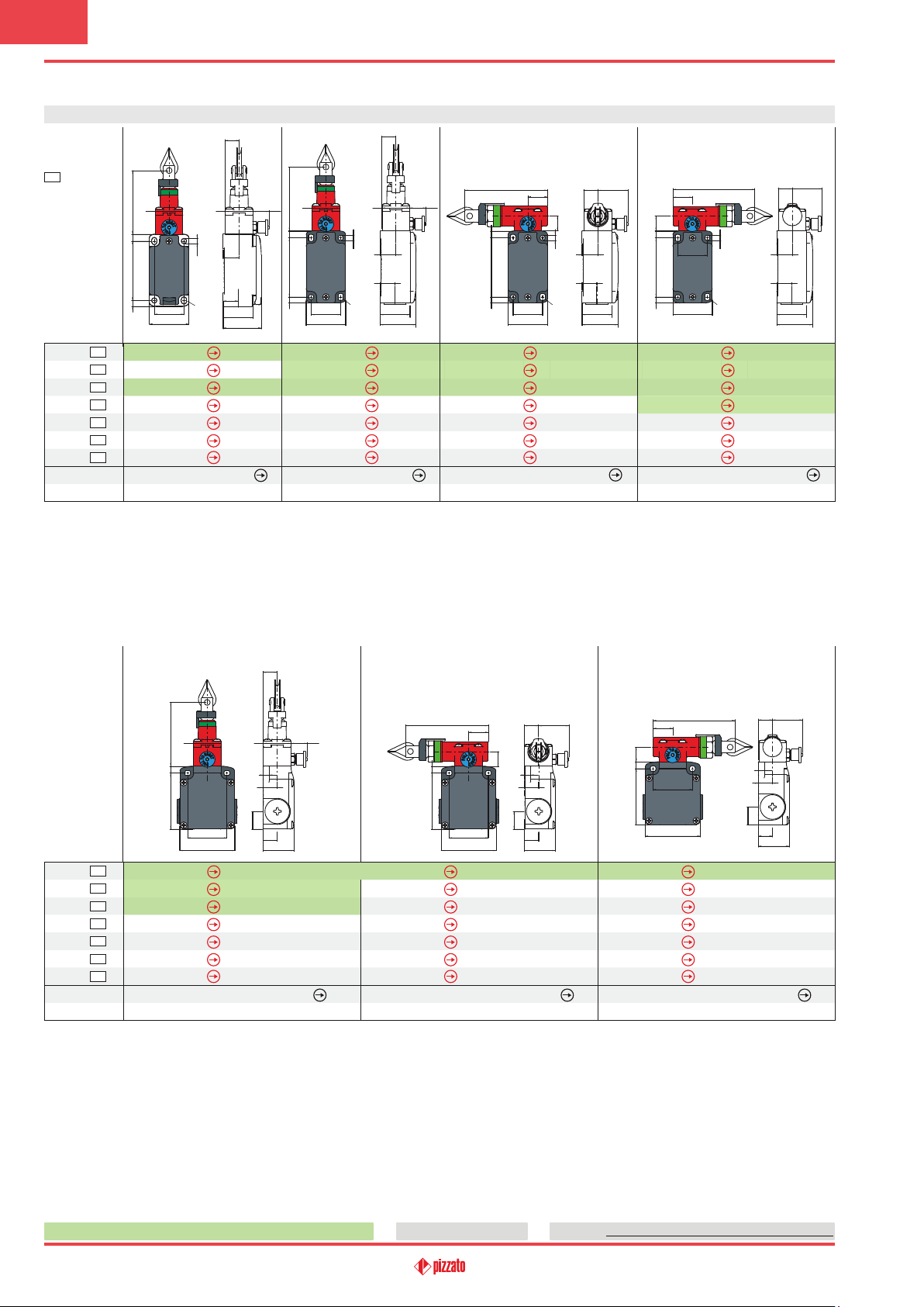
8
Safety rope switches with reset for emergency stop
Dimensional drawings
Contact type:
= slow action
L
65
28
7
60
5.9
30
Contact block
18
9
20
21
22
33
34
Actuating force
Travel diagrams
L
L
L
L
L
L
L
40
FP 1878-M2
FP 978-M2
FP 2078-M2
FP 2178-M2
FP 2278-M2
FP 3378-M2
FP 3478-M2
Initial 63 N…final 83 N (90 N )
page 174 - group 1
14.5
28 16.7 - 20.2
5.4
16.2
15.2
5.4x7.4
30.4
38.6
1NO+1NC
2NC
1NO+2NC
3NC
2NO+1NC
1NO+1NC
2NC
14.5
65
28
7
606.2
30
40
FD 1878-M2
FD 978-M2
FD 2078-M2
FD 2178-M2
FD 2278-M2
FD 3378-M2
FD 3478-M2
Initial 63 N…final 83 N (90 N )
28 16.7 - 20.2
5.3
16
15
5.3x7.3
30.4
36.5
1NO+1NC
2NC
1NO+2NC
3NC
2NO+1NC
1NO+1NC
2NC
page 174 - group 1
7
606.2
FD 1883-M2
FD 983-M2
FD 2083-M2
FD 2183-M2
FD 2283-M2
FD 3383-M2
FD 3483-M2
84
20
30
40
15
5.3
5.3x7.3
1NO+1NC
2NC
1NO+2NC
3NC
2NO+1NC
1NO+1NC
2NC
14.5 30.8 - 34.3
16
15
Initial 147 N…final 235 N (250 N )
page 174 - group 2
30.4
36.5
All values in the drawings are in mm
20
15
7
606.2
FD 1884-M2
FD 984-M2
FD 2084-M2
FD 2184-M2
FD 2284-M2
FD 3384-M2
FD 3484-M2
84
5.3
30
5.3x7.3
40
14.5 30.8- 34.3
16
15
1NO+1NC
2NC
1NO+2NC
3NC
2NO+1NC
1NO+1NC
2NC
Initial 147 N…final 235 N (250 N )
page 174 - group 2
30.4
36.5
Contact block
18
9
20
21
22
33
34
Actuating force
Travel diagrams
L
L
L
L
L
L
L
65
28
757
40
56
FL 1878-M2
FL 978-M2
FL 2078-M2
FL 2178-M2
FL 2278-M2
FL 3378-M2
FL 3478-M2
1NO+1NC
2NC
1NO+2NC
3NC
2NO+1NC
1NO+1NC
2NC
Initial 63 N…final 83 N (90 N
page 174 - group 1
14.5
28 16.7 - 20.2
6.5
14.5
18
14.5
31.5
)
84
20
15
18
40
56
1NO+1NC
2NC
1NO+2NC
3NC
2NO+1NC
1NO+1NC
2NC
FL 1883-M2
FL 983-M2
FL 2083-M2
FL 2183-M2
FL 2283-M2
FL 3383-M2
FL 3483-M2
757
Initial 147 N…final 235 N (250 N )
page 174 - group 2
14.5 30.8 - 34.3
6.5
14.5
14.5
31.5
14.5 30.8- 34.3
18
15
757
FL 1884-M2
FL 984-M2
FL 2084-M2
FL 2184-M2
FL 2284-M2
FL 3384-M2
FL 3484-M2
84
20
40
56
1NO+1NC
2NC
1NO+2NC
3NC
2NO+1NC
1NO+1NC
2NC
Initial 147 N…final 235 N (250 N )
page 174 - group 2
14.5
14.5
6.5
31.5
Items with code on green background are stock items
173
Accessories See page 299
The 2D and 3D files are available at www.pizzato.com
General Catalogue Safety 2017-2018
Page 6
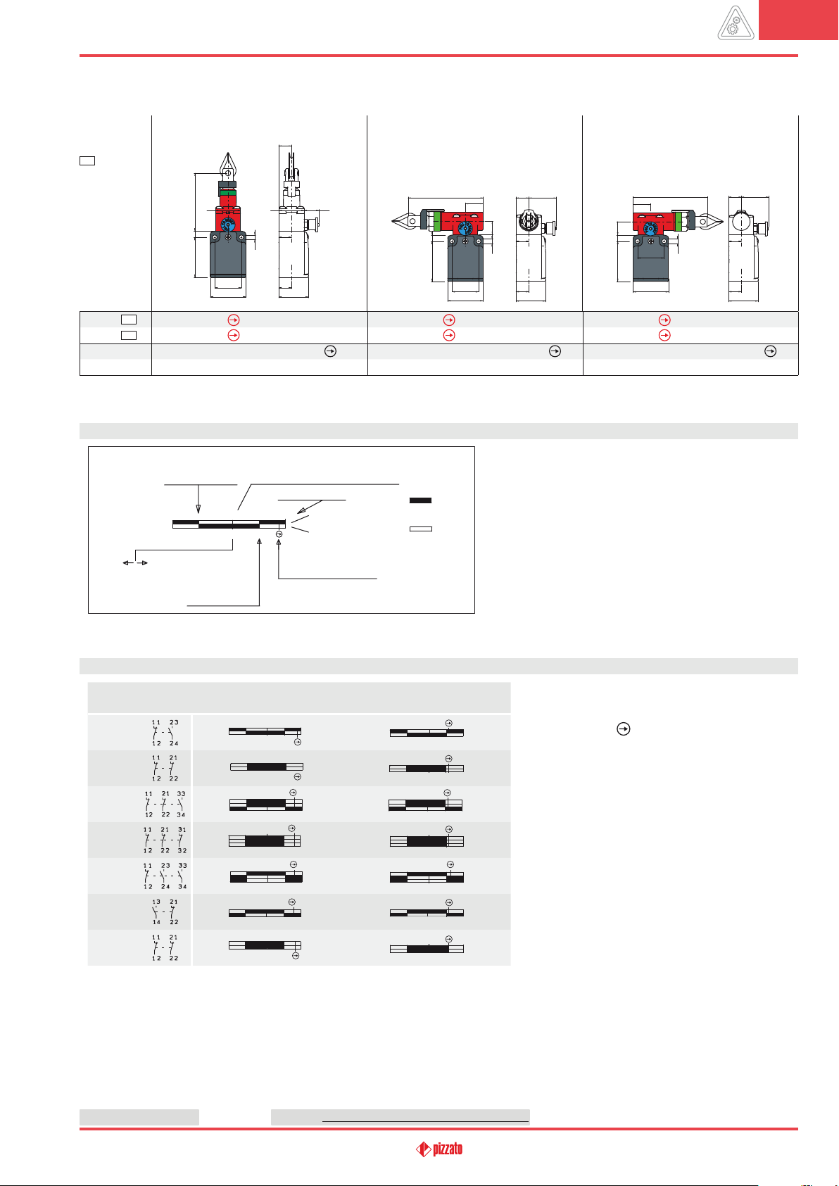
8
Contact type:
= slow action
L
Contact block
33
34
Actuating force
Travel diagrams
L
L
65
28
45.5 7
30
40
FC 3378-M2
FC 3478-M2
Initial 63 N…final 83 N (90 N )
page 174 - group 1
14.5
28 16.7 - 20.2
14.5
5.3
14.5
1NO+1NC
2NC
33.4
FC 3383-M2
FC 3483-M2
84
20
45.5 7
30
40
1NO+1NC
2NC
15
5.3
14.5 30.8 - 34.3
14.5
14.5
Initial 147 N…final 235 N (250 N )
page 174 - group 2
33.4
20
15
45.5 7
FC 3384-M2
FC 3484-M2
84
5.3
30
40
1NO+1NC
2NC
14.5 30.8- 34.3
14.5
14.5
33.4
Initial 147 N…final 235 N (250 N )
page 174 - group 2
How to read travel diagrams All values in the diagrams are in mm
Cut of
the rope
NC opening
NO closing
Reset actuated
0
Traction of
the rope
Ideal rope tension (middle of green area)
4
R1.5
S
NC opening
NO closing
Reset actuated
Maximum travel
8.5
R6.5
8
Positive opening travel
23-24
11-12
Example diagram
Closed contact
Open contact
Travel diagrams table
Contact block
18
1NO+1NC
9
2NC
20
1NO+2NC
21
3NC
22
2NO+1NC
33
1NC+1NO
34
2NC
Group 1 Group 2
0 8.5
4
S
R6.5
R1.5
4
0 8.5
S
R6.5R1.5
0 8.5
0 8.5
0 8.5
0 8.5
0
R1.5
8
4
S
R6.5R1.5
8
4
S
R6.5R1.5
8
4
S
R6.5R1.5
8
4
S
R6.5R1.5
4
S
R6.5
8
8
8
8.5
0 16
0 16
0
0 16
0 16
0 16
0 16
R4.5
R4.5
R4.5
R4.5
R4.5
R4.5
R4.5
IMPORTANT:
In safety applications, actuate the switch at least up
14
8
S
R12
14
8
S
R12
14
8
16
S
R12
14
8
S
R12
14
8
S
R12
14
8
S
R12
14
8
S
R12
to the positive opening travel shown in the travel diagrams with symbol . Actuate the switch at least with
the positive opening force, reported in brackets below
each article, next to the actuating force value.
Accessories See page 299 The 2D and 3D files are available at www.pizzato.com
General Catalogue Safety 2017-2018
174
Page 7
8
Safety rope switches with reset for emergency stop
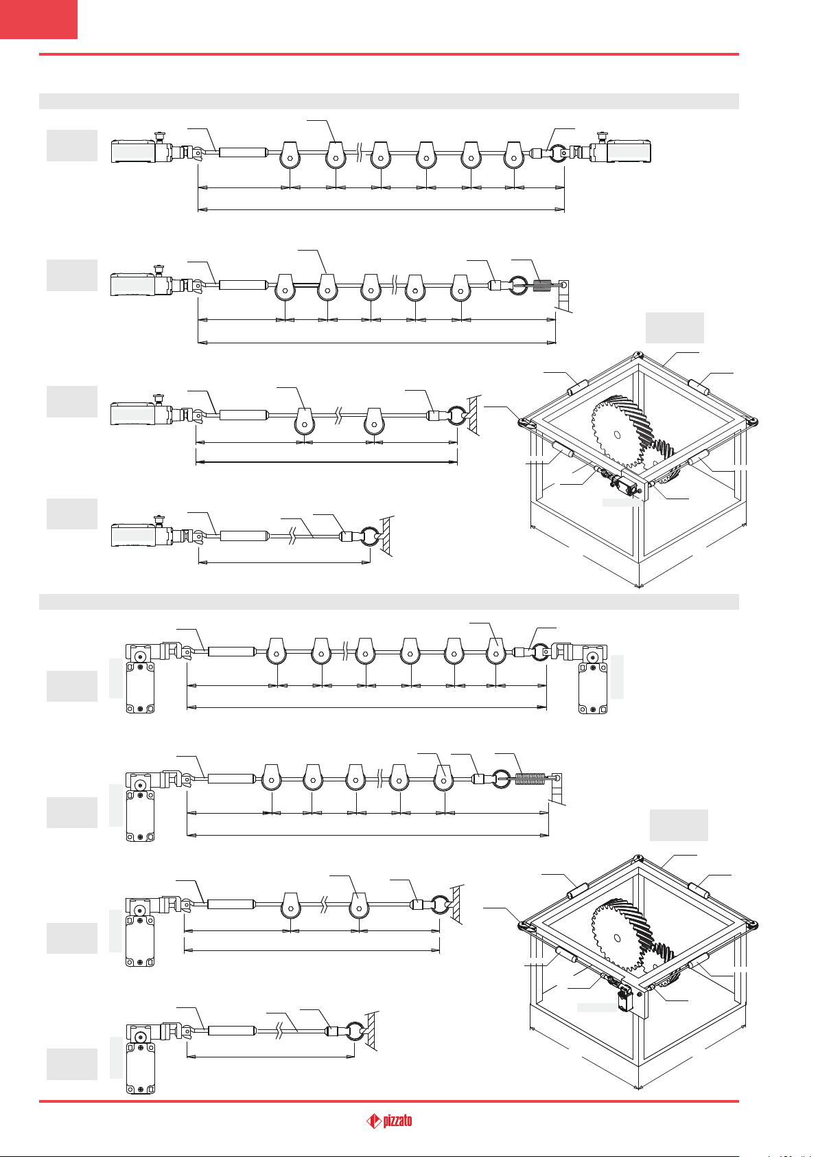
Application examples and max. rope length for switches with longitudinal head
VF AF-CA5
VF F05
6 m MAX
VF AF-CA5
VF AF-CA5
12 m MAX
VF AF-MR5
24 m MAX
18 m MAX
VF AF-MR5
VF AF-MR5
VF AF-MR5
VF AF-ME78
VF AF-CA10
VF AF-IFGR03
VF AF-MR5
3 m max
Example
A
Example
B
Example
C
Example
D
VF AF-TR5
FD 1878-M2
2 ÷ 3 m 2 ÷ 3 m 2 ÷ 3 m 2 ÷ 3 m 2 ÷ 3 m 2 ÷ 3 m 2 ÷ 3 m
VF AF-TR5
FD 1878-M2
2 ÷ 3 m 2 ÷ 3 m 2 ÷ 3 m 2 ÷ 3 m 2 ÷ 3 m 2 ÷ 3 m
VF AF-TR5
FD 1878-M2
2 ÷ 3 m 2 ÷ 3 m 2 ÷ 3 m
VF AF-TR5
FD 1878-M2
FD 1878-M2
FD 1878-M2
Example
E
VF F05
VF AF-IFGR03VF AF-IFGR03
VF AF-IFGR03
VF AF-TR8
3 m max
Application examples and max. rope length for switches with transversal head
Example
F
Example
G
Example
H
FD 1884-M2 FD 1884-M2 FD 1884-M2
VF AF-TR5
VF AF-TR5
VF AF-TR5
VF AF-TR5
VF AF-CA5
3 ÷ 5 m 3 ÷ 5 m 3 ÷ 5 m 3 ÷ 5 m 3 ÷ 5 m 3 ÷ 5 m 3 ÷ 5 m
70 m MAX
VF AF-MR5
VF AF-CA5
3 ÷ 5 m 3 ÷ 5 m 3 ÷ 5 m 3 ÷ 5 m 3 ÷ 5 m 3 ÷ 5 m
50 m MAX
VF AF-CA5
3 ÷ 5 m 3 ÷ 5 m 3 ÷ 5 m
35 m MAX
VF AF-MR5
VF F05
VF AF-MR5
VF AF-ME80
VF AF-MR5
VF AF-CA10
VF AF-IFGR03
VF AF-MR5
FD 1880-M2
FD 1883-M2
FD 1883-M2
Example
J
VF F05
VF AF-IFGR03VF AF-IFGR03
VF AF-IFGR03
VF AF-TR8
Example
175
16 m MAX
I
FD 1884-M2
3 m max
5 m max
3 m max
5 m max
General Catalogue Safety 2017-2018
Page 8
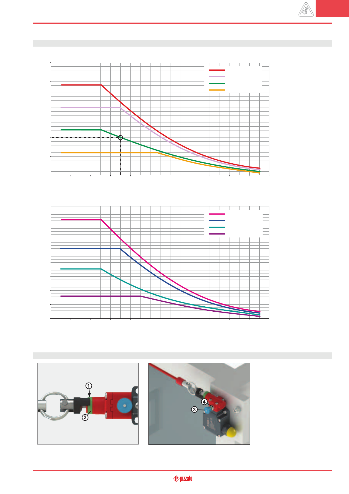
Maximum spans
30
25
20
15
10
Max. rope length (m)
5
0
0 10 20 30 40 50 60 70 80 90 100
Maximum spans for switches with longitudinal head
Temperature difference (°C)
example A
example B
example C-E
example D
8
The max. recommended
spans are indicated in the
diagram as a function of the
temperature fluctuations
(temperature differences)
to which the switch may be
exposed at the point of use.
For instance, with installation of type C and a temperature difference of 30°C,
the max. recommended
rope length is 10 metres.
Maximum spans for switches with transversal head
80
70
60
50
40
Max. rope length (m)
30
20
10
0
0 10 20 30 40 50 60 70 80 90 100
Temperature difference (°C)
Important: The above data are guaranteed only using original rope and accessories. See page 185.
example F
example G
example H-J
example I
Adjustment of the switching point
Tighten the rope connected to the switch, until the
end of the indicator (1) reaches about the middle of
the green ring (2).
General Catalogue Safety 2017-2018
Pull the knob (3) in order to close the safety contacts inside the switch. Below the knob a green ring
(4) will be disclosed.
176
 Loading...