

Page 1
10B
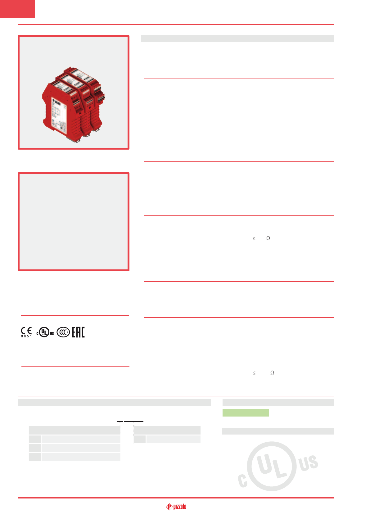
Safety module CS AR-51
Module for emergency stops, end position
monitoring for movable guards, safety mats
and safety bumpers with 4-wire technology
Main features
•For safety applications up to SIL CL 3/PL e
•Input with 2 channels
•Choice between automatic start, manual start
or monitored start
•Connection of input channels of opposite
potentials
•Can be connected to electromechanical
contacts, safety mats or safety bumpers with
4‑wire technology
•Output contacts:
2 NO safety contacts,
•Supply voltage:
24 Vac/dc
Utilization categories
Alternating current: AC15 (50…60 Hz)
Ue (V) 230
Ie (A) 3
Direct current: DC13 (6 oper. cycles/min.)
Ue (V) 24
Ie (A) 4
Quality marks and certificates:
EC type examination certificate: IMQ CP 432 DM
UL approval: E131787
CCC approval: 2013010305640211
EAC approval: RUC-IT.AД35.В.00454
Compliance with the requirements of:
Low Voltage Directive 2014/35/EU,
Machinery Directive 2006/42/EC,
EMC Directive 2014/30/EU
Technical data
Housing
Polyamide housing PA 66, self‑extinguishing V0 acc. to UL 94
Protection degree: IP40 (housing), IP20 (terminal strip)
Dimensions: see page 295, design A
General data
SIL CL: up to SIL CL 3 acc. to EN 62061
Performance Level (PL): up to PL e acc. to EN ISO 13849‑1
Safety category: up to cat. 4 acc. to EN ISO 13849‑1
Safety parameters: see page 349
Ambient temperature: ‑25°C…+55°C
Mechanical endurance: >10 million operating cycles
Electrical endurance: >100,000 operating cycles
Pollution degree: external 3, internal 2
Impulse withstand voltage (U
Rated insulation voltage (U
Overvoltage category: II
Weight: 0.3 kg
Supply
Rated supply voltage (U
Max. DC residual ripple in DC: 10%
Supply voltage tolerance: ±15% of U
Power consumption AC: < 5 VA
Power consumption DC: < 2.5 W
Control circuit
Protection against short circuits: PTC resistance, Ih=0.5 A
PTC times: Response time > 100 ms, release time > 3 s
Maximum resistance per input:
Current per input: 10 mA (typical)
Min. duration of start impulse t
Response time t
Release time t
Release time in absence of power supply t
Simultaneity time t
: < 120 ms
A
: < 15 ms
R1
: unlimited
C
In compliance with standards:
EN 60204‑1, EN ISO 13855, EN 1037, EN ISO 12100, EN ISO 13850, EN 60529,
EN 61000‑6‑2, EN 61000‑6‑3, EN 61326‑1, EN 60664‑1, EN 60947‑1, EN ISO 13849‑1,
EN ISO 13849‑2, EN 62061, UL 508, CSA C22.2 n° 14‑95
Output circuit
Output contacts: 2 NO safety contacts
Contact type: forcibly guided
Material of the contacts: gold‑plated silver alloy
Maximum switching voltage: 230/240 Vac; 300 Vdc
Max. current per contact: 6 A
Conventional free air thermal current (Ith): 6 A
Max. total current Σ Ith
2
Minimum current: 10 mA
Contact resistance:
External protection fuse: 4 A
The number and the load capacity of output contacts can be increased by using expansion modules or
contactors. see page 241‑250.
): 4 kV
imp
): 250 V
i
): 24 Vac/dc; 50…60 Hz
n
n
200
: > 150 ms
MIN
: < 100 ms
R
: 36 A
2
100 m
Code structure
CS AR-51V024
Connection type
V
Screw terminals
M Connector with screw terminals
X Connector with spring terminals
217
Supply voltage
024
24 Vac/dc
Stock items
CS AR-51V024
Features approved by UL
Rated supply voltage (Un): 24 Vac/dc; 50…60 Hz
Power consumption AC: < 5 VA
Power consumption DC: < 2 W
Maximum switching voltage: 230 Vac
Max. current per contact: 6 A
Utilization category C300
Notes:
‑ Use 60 or 75 °C copper (Cu) conductors, rigid or flexible, wire size 30‑12 AWG.
‑ Tightening torque for terminal screws of 5‑7 lb in.
‑ Only for 24 Vac/dc versions: power supply only with class 2 sources or with
limited voltage and energy. (Supply from Remote Class 2 Source or limited
voltage limited energy).
General Catalogue Safety 2017-2018
Page 2
A1/A2
S31/S32
S21/S22
S33/S34 (START)
13/14, 23/24
tAt
R1
t
R1
t
A
t
R
t
MINtA
A1/A2
S31/S32
S21/S22
S33/S34 (START)
13/14, 23/24
t
A
t
R1
tR1t
A
t
R
t
MIN
K1
K2
LED
CH1/CH2
EXT.
FAULT
A1
S32
S33
S31
S34
S37
13
23
A2
S21
S22
14
24
PWR
LED
LED
PE
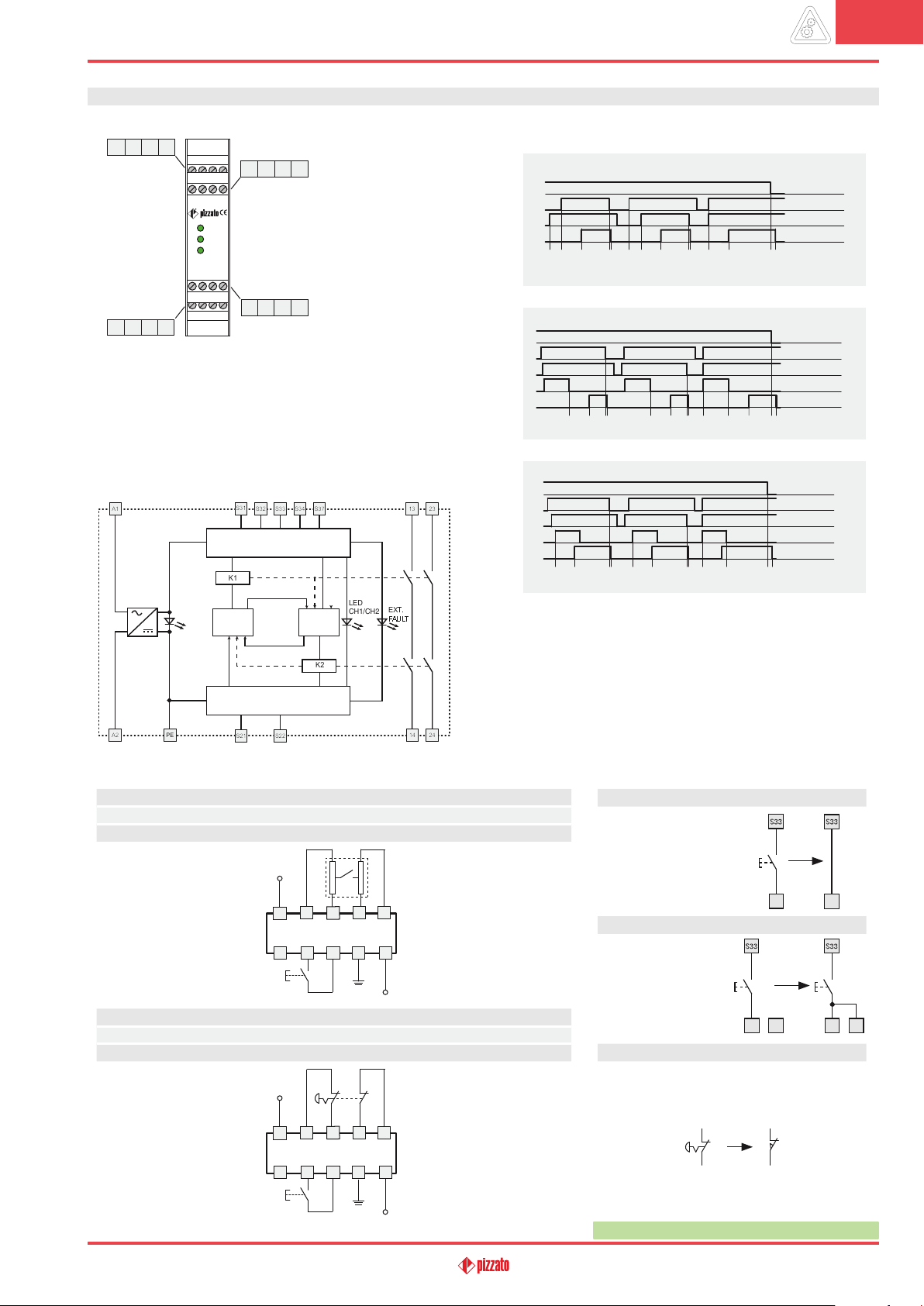
Safety module CS AR-51
Pin assignment
A1 13 23
S31 S32 S21
ITALY
PWR
CH1/CH2
EXT.
FAULT
PE S33 S34
A2 14 24
The signal thereby generated causes the EXT.FAULT LED to illuminate and signal the short‑
circuit and the opening of the output contacts, resulting in the blocking of the control circuit and
causing the machine to switch to the safety setting. The EXT. FAULT LED does not switch on if
the wires or internal connections of the safety mat or safety bumper are interrupted.
PE terminal connection
The PE terminal has to be connected
to the equipotential circuit of machine
S22
protection if it is necessary.
This connection is made for functional
reason, to reduce effects of an insulation
fault on the machine operation.
In particular, ground faults in control
circuits must not cause unwanted start‑up
or dangerous movements or prevent the
machine from stopping.
Function of “EXT. FAULT” LED
When a pressure is exerted on the surface
of a safety bumper or safety mat, a short‑
circuit occurs between the two conductive
S37
elements, which constitute the apparatus
and can be connected to the input
channels of the safety module.
Function diagrams
Configuration with automatic start
tCt
Configuration with monitored start
tR1tCt
A
A
10B
A1/A2
S31/S32
S21/S22
t
t
R1
A
t
R
13/14, 23/24
Internal block diagram
L / +
N / -
Input configuration
INTERFACE
LOGIC LOGIC
INTERFACE
Safety mats and safety bumpers
Input configuration with manual start
2 channels
L / +
A1
S37 S33
S31
CS AR-51
S32
S34
S22
S21
PE
Emergency stop circuits
Input configuration with manual start
2 channels
L / +
A1
S37 S33
S31
CS AR-51
S32
S34
S22
S21
PE
Configuration with manual start
Legend:
t
: Min. duration of start impulse
MIN
tC: simultaneity time
tA: response time
t
: release time
R1
: release time in absence of
t
R
power supply
Automatic start
With regard to the
indicated diagrams, bridge
the start button between
S33 and S34 in order to
activate the automatic
start module.
S34 S34
Monitored start
A2
With regard to the
indicated diagrams,
establish the connection
N / -
between S34 and S37
in order to activate the
monitored start module.
S34
S37
S34
S37
Movable guard monitoring
The safety module can monitor emergency stop
circuits and control circuits for movable guards.
Replace the emergency stop contacts with the switch
contacts.
A2
The diagram does not show the exact position of the terminals in the product
General Catalogue Safety 2017-2018
N / -
Items with code on green background are stock items
218
 Loading...