


PANNELLO OPERATORE
TOUCH SCREEN
TD570 - TD700
Manuale
operatore

2
SUMMARY
1 Introduction .............................................................................. 3
2 Ordering codes ........................................................................ 3
3 Optional devices ...................................................................... 3
4 Dimensions and installation ..................................................... 3
5 Hardware data ......................................................................... 6
Mechanical features ....................................................................... 6
Standard Hardware configuration .................................................. 6
Display and Lamp TD570 .............................................................. 6
Display and Lamp TD700 .............................................................. 6
Connections ................................................................................... 6
6 Electrical wirings ...................................................................... 8
6.1 Terminal block M1 ............................................................. 9
6.2 Ethernet connection ........................................................... 9
6.3 USB connections ............................................................. 10
6.4 COM1 RS232 connector .................................................. 11
6.5 Audio connector ............................................................... 13
6.6 SD/MMC connector ......................................................... 13
6.7 USB-Device connector..................................................... 14
6.8 ETD-EXP connector for data acquisition modules ........... 15
7 Setting of dip-switches ........................................................... 16
7.1 Serial dip-switches ........................................................... 17
7.2 CPU dip-switches ............................................................ 18
7.3 COM1 dip-switches .......................................................... 20
8 Connecting the Terminal to PC .............................................. 21
8.1 Connection to PC by ActiveSync ..................................... 21
8.2 Connection by FTP .......................................................... 23
8.3 Remote desktop ............................................................... 25
9 Auto-start of selected applications ......................................... 26
9.1 Create autorun.lnk file ...................................................... 27
10 Installation program ............................................................... 29
11 Software applications ............................................................. 29
12 Notes / Updates ..................................................................... 31

3
1 Introduction
Thanks for choosing a Pixsys device.
TD570/TD700 is a Touch-screen graphic Terminal and HMI,
Windows-CE based.
Sealing of front panel according to IP54, box sealing according to
IP30.
2 Ordering codes
TD570-AD
TOUCH PANEL 5,7” - 640x480
Power supply 12..24V AC/DC ±15% 50/60Hz
TD700-AD
TOUCH PANEL 7” - 800x480
Power supply 12..24V AC/DC ±15% 50/60Hz
3 Optional devices
4 Dimensions and installation
TD570-AD:
ETD884-AD
Expansion module for load cells; 8 digital I/O, 2
analogue outputs V/mA

4
3
4
m
m
1
6
0
m
m
179 mm
204 mm
4
Spessore suggerito
2 9 mm
Suggested thickness
÷
Dima di foratura
180 x 144 mm
Frontal panel cut-out
143 mm
17
32m m
inserim ento
Memor y Card
32mm
insert
Memory Card
Memory Card (opt ional)
Cod . CA RD SD
SD
Esp ansione (opt ional)
Cod . ETD884-AD
TD700-AD:

5
3
4
m
m
179 mm
204 mm
4
Spessore suggerito
2 9 mm
Suggested thickness
÷
Dima di foratura
180 x 144 mm
Frontal panel cut-out
143 mm
17
32mm
inserimento
Memory Card
32mm
insert
Memory Card
Memory Card (optional)
Cod. CARD SD
SD
CARD
Espansione (optional)
Cod. ETD884-AD

6
5 Hardware data
Mechanical features
Front panel
dull anodized aluminium 8mm
Standard Hardware configuration
CPU
ARM V4i 200 MHz
Audio
AC ’97 SoundMAX® Codec
Display and
Lamp
TD570
T
ype
LCD TFT touch screen
Dimensions
Active area 5.7”
Resol
ution
640 x 480
Pixel dimension
0.18 x 0.18 mm
Colo
rs
16 millions
Lamp life
10000 h typical
Lamp power
1.9 W
Display and
Lamp
TD700
T
ype
LCD TFT touch screen
Dimensions
Active area 7”
Resolution
800 x 480
Pixel dimension
0.1905 x 0.1905 mm
Col
o
rs
16 millions
Lamp life
20000 h typical
Lamp power
1.58 W
Connections
Expansion slot
1 data acquisition Slot
COM
ports
1 LAN (10/100), Ethernet RJ-45
1 RS232 opto-isolated
1 RS485 opto-isolated
1 CAN opto-isolated

7
I/O Port
2 rear USB port 2.0 12 Mbits/S 150mA
Audio
1 line Out
Power supply
12..24V AC/DC ±15% 50/60Hz
Power consumption
Typical 3,7 W Max 4,8 W

8
6 Electrical wirings
Although this device has been designed to resist
noises in an industrial environment, please notice the
following safety guideli
nes
•
Separate control lines from power wires
•
Avoid proximity of remote control switch
es,
electromagnetic meters, powerful engines
•
Avoid proximity of power groups, especially if
phase-controlled
View of connectors on TD570-AD and TD700-AD:
SD
CARD
USB Device
M1
DIP1
USB1
USB2-2
ETH1
DIP2 DIP3
JK1
COM1
ETD-EXP1
ETD-EXP2

9
6.1 Terminal block M1
M1
1 Positive power supply of device
2 Ground power supply of device
3 Rs485+ opto-isolated
4 Rs485+ opto-isolated
5 Isolated ground for serial
6 CAN H opto-isolated serial
7 CAN L opto-isolated serial
6.2 Ethernet connection
Connector RJ45
M1
DIP1
USB1
USB2-2
ETH1
DIP2 DIP3
COM1
ETD-EXP1
ETD-EXP2

10
Ethernet Connector 10/100 Base-T available on rear side of
Terminal, below terminal block of power supply. It allows to
connect the device to local network.
Green led indicates that link is available and device is connected
to network.
Yellow led indicates that data transmission/receipt is in progress.
6.3 USB connections
The device is provided with two USB 2.0 connectors.
USB1 is located on the rear side of the Terminal beside RJ45
Ethernet connector :
M1
DIP1
USB1
USB2-2
ETH1
DIP2 DIP3
COM1
ETD-EXP1
ETD-EXP2
USB2 is located on the front panel and it is protected by a silicon
cover:

11
The connector on front panel allows to connect plug&play
peripheral devices also when the Terminal is panel-mounted.
USB Peripheral devices include keyboards, mouse, serial
converters, barcode readers etc.
Max current available on USB connector is 150mA.
If using pendrives, the system will rename “Harddisk” the first
inserted pendrive and “Harddisk2” the second pendrive.
6.4 COM1 RS232 connector
COM1 RS232
1
2
SIN
Serial In or Receive Data
3
SOUT
Serial Out or Transmit
Data
4
RS-
RS485 – (A)
5
GNDi
Serial isolated ground
6
DSR
Data Set Ready
COM 1
FE
MALE /
FEMMINA

12
7
RTS
Request To Send
8
9
RS+
RS485 + (B)

13
6.5 Audio connector
Audio Jack 3.5mm
JK1
A non-amplified stereo output is located on the right side of the
device.
6.6 SD/MMC connector
SD/MMC reader, push-pull type
SD
CARD
USB Device
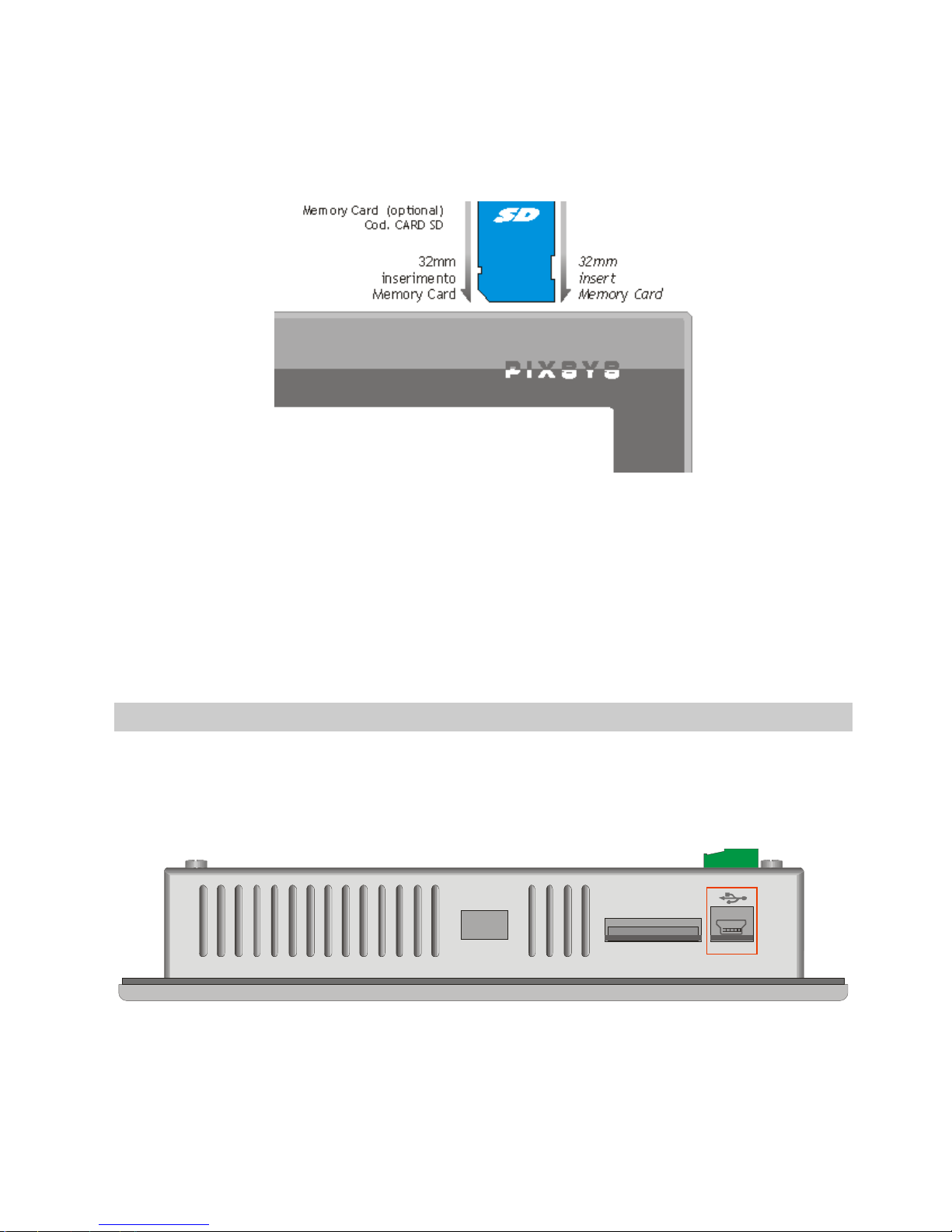
14
The connector is located on the upper side of the device , close to
mini-usb connector. It is push-pull type, therefore enter memory
card till a click is produced and release it (see diagram below ).
To extract the Memory, press it until a click is produced and pull it.
The device can support SD and MMC memories up to 2GB, it
does not support SD-cards HC.
The operating system identifies the memory as “StorageCard”.
6.7 USB-Device connector
Mini-USB connector type B
SD
CARD
USB Device
Located on the upper side of the device beside the SD/MMC slot,
it is conceived only for connection to Windows-based PC.

15
6.8 ETD-EXP connector for data acquisition modules
Connectors for data acquisition modules :
M1
DIP1
USB1
USB2-2
ETH1
DIP2 DIP3
COM1
ETD-EXP1
ETD-EXP2
The “ETD-EXP1” “ETD-EXP2” connectors allow quick connection
of proprietary expansion slots for data acquisition purpose. Please
proceed as follows:
Switch the device off, disconnect power supply, enter the
expansion slot , fix the four screws contained in the package,
connect power supply and switch the device on.

16
Example of connection ETD884-AD:
SD
CARD
7 Setting of dip-switches
TD570/TD700 are provided with some internal dip-switches
(which may be accessed by special holes on the enclosure),
allowing the user to adapt the device to specific requirements.
N.B.: Switch the device off and disconnect power supply
before proceeding to any hardware setting.

17
7.1 Serial dip-switches
DIP1 is conceived to set the serial communication. It is placed
underneath power supply terminal block, therefore the terminal
block must be removed in order to get access to DIP1.
The following table shows the optional settings of this dip-switch:
Input type
Dip
-
switch
Notes
Desabled
Default setting

18
CAN
Termination
Chiude tra linee CANH e CANL
una resistenza di terminazione di
120 Ohm.
RS485
Termination
Close a termination resistor
330Ohm between RS485+ and
RS485-
Polarization
RS485
Close polarization resistors on
RS485 line
If the device is used as Master RS485, the dip-switches will have
to be set as “RS485 polarization”.
If the device is used as Slave RS485, the dip-switches must be set
as “RS485 termination”.
Beside terminal block “M1” there are two signal LEDs. The yellow
LED indicates that data are being received on RS485. The green
LED indicates that data transmission in in progress on RS485. In
this case the LED is ON only if dip 3 and 4 of DIP1 are set to ON,
with consequent polarization of RS485 line.
7.2 CPU dip-switches
DIP2 is located at the bottom rear side.

19
M1
DIP1
USB1
USB2-2
ETH1
DIP2 DIP3
COM1
ETD-EXP1
ETD-EXP2
This dip-switch enables/desables the protection of flash memory
writing.
Preventing the writing on flash-memory it will not be possible to
create/save new files. The table below provides the list of possible
configurations:
Input type
Dip
-
swit
ch Notes
Default
Default position: configuration for
TD570/TD700.
Prevent
writing on
flash memory
Raising “DIP2” to ON , the writing
on flash memory is not allowed.
N.B.: Dips no. 1, 3 and 4 are directly connected to CPU and
they identify the type of device currently used. Therefore their

20
tampering may affect the correct operation of the Touchscreen!
7.3 COM1 dip-switches
"DIP3" dip-switch allows selection between debug serial port (to
be used for software developments) and system COM1 serial port.
Both serial ports are available on 9poles connector with RS232
protocol.
M1
DIP1
USB1
USB2-2
ETH1
DIP2 DIP3
COM1
ETD-EXP1
ETD-EXP2
Dip-switches have to be selected as follow:
Input type
Dip
-
switch
Note
s
RS232 COM1
Serial
COM1 serial port enabled

21
RS232 debug
serial
Debug serial port enabled
8 Connecting the Terminal to PC
8.1 Connection to PC by ActiveSync
TD570/TD700 are relying on Windows CE operating system,
therefore they can be easily connected to any Windows-based PC.
To connect the device to a PC, it is necessary to get a USB type
A - mini USB type B cable (Pixsys code 1620.00.082) and the
software ActiveSync (for Windows 2000 up to Windows XP) or
alternatively the Windows Mobile Device Centre (for Windows
Vista and Windows 7).
Both applications are available for free download at
www.microsoft.com.
After installing the above mentioned software applications, power
up the device and connect it to PC by USB cable. It will take a few
minutes for the PC to automatically install the device (this will take
place only at the first connection).
Once the installation of drivers will be completed, the following
window will be automatically visualized:

22
Windows 2000..Windows XP
Windows Vista and Windows 7
By means of these software tools, the device is identified by the
PC as a mass storage peripheral and this way it will be possible to
explore files and transfer them from PC to device and viceversa.

23
8.2 Connection by FTP
TD570/TD700 support FTP protocol and this allows network files
transfer between PC and Terminal.
To access the folders on the device, just open “Explorer” and type:
“ftp://anonymous:anonymous@192.168.0.100” (being
“192.168.0.100” the IP address of the device).
To get the IP address of the device just double-click on network
icon on Windows taskbar. A screenshot containing all details
about network will be displayed.

24
Anyway we suggest to use an FTP client for data transfer, as this
is normally simpler and quicker to use.
An example is FileZilla Client FTP, available for free download at
http://filezilla-project.org/download.php

25
8.3 Remote desktop
The device is integrating Remote Desktop feature.
This requires “cerdisp.exe” to be run on the device (it is already
pre-installed on it) and “cerhost.exe” to be run on PC.
As a first step the device must be connected to local network, then
double-click the desktop “Cerdisp” icon
Click on START icon of the form :

26
At this stage run the “cerhost.exe” application on the PC which will
be used to control the TD430.
A window with different options will be displayed , click on “File”
and then on “Connect”.
A further window will show in a few seconds a list of devices
available for connection.
Double-click the selected device to immediately visualize the
remote desktop, allowing full control of the connected device.
9 Auto-start of selected applications
The device integrates also the possibility to run automatically
some selected applications.
How it works : a link file (.lnk) is created on the “Nandflash” disk of
the device (called “root” from now on) and it is named
“autorun.lnk”, pointing to the application which should be run
automatically at startup.
Autorun.lnk files are handled by the software as follows: the
application pointed by the autorun available on the device root will
be run first; in case a USB peripheral or a memory card are
inserted at startup, the software will stop the application running
27
on the device and will start the application pointed by the
autorun.lnk available on the root of the USB peripheral or of the
memory card.
9.1 Create autorun.lnk file
N.B.: Whenever an application is run automatically by
autorun, Windows desktop is not run. Therefore if the running
application should be closed, the device will still display the
latest window.
To remove the autostart, it is necessary to connect the device
to PC and delete the “autorun.lnk” file. Restarting the device
it will be possible to visualize the standard desktop.
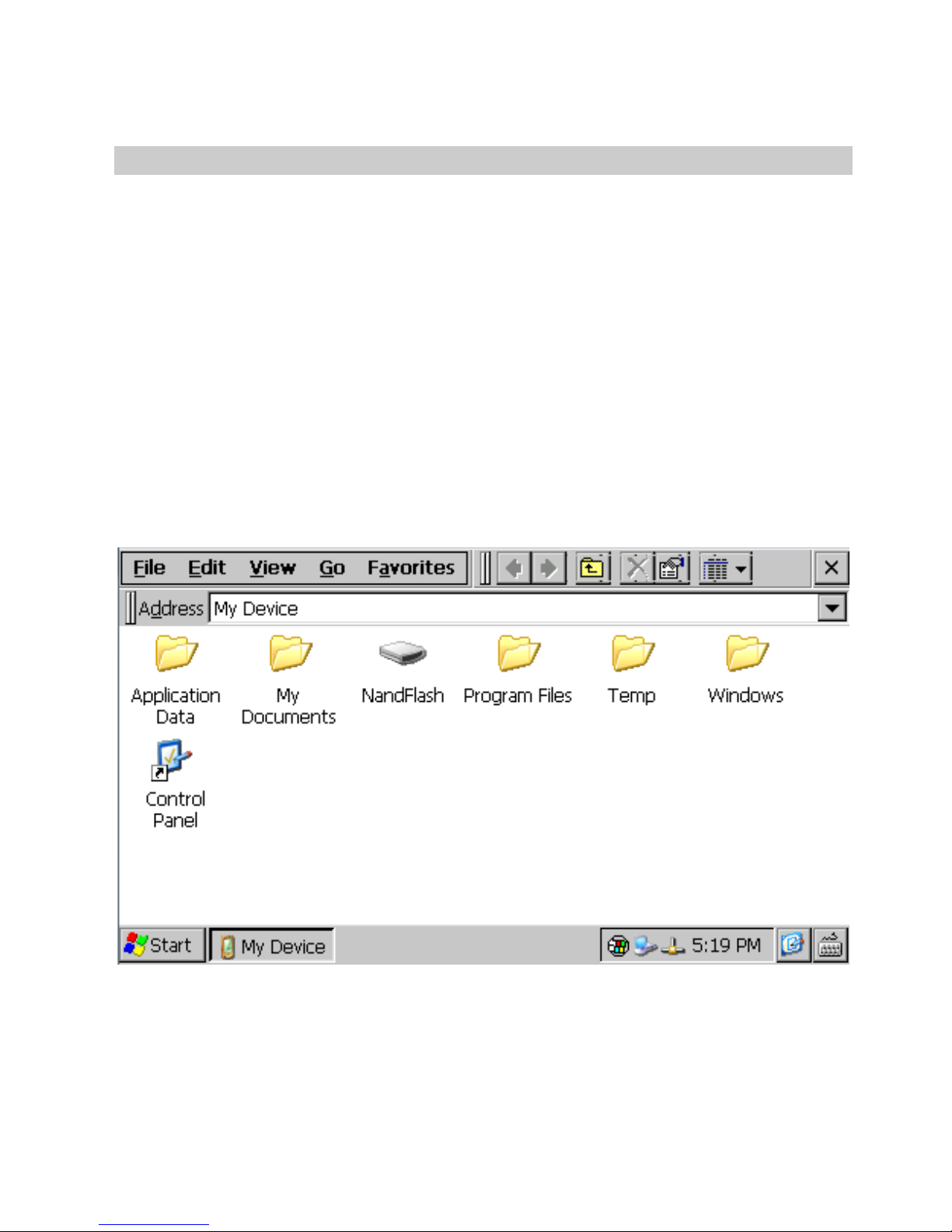
To create the “autorun.lnk” file follow the steps below: double-click
“My device” icon available on desktop and go to the Directory
containing the selected application.
Select the file, click “Edit” and “Copy”

28
Go to the device root (nandflash) or to USB peripheral (Harddisk)
and click “Edit” and “Paste Shortcut”.
Open video keyboard and rename the Autorun file
Restarting the device, the application pointed by the created
Autorun file will automatically start.

29
10 Installation program
Software applications to be installed on TD570/TD700 must be
compatible with Windows CE for ARM V4i platform
Usually these applications are provided as a single installation file
with .CAB extension.
The installer service already stored on the device will automatically
recognize the installation package and will guide the user step by
step through the correct proceeding.
Pixsys has also developed an installer package which recognizes
the proprietary installation files with .zTd extension. This
application and the installation files are supplied exclusively by
Pixsys.
11 Software applications
TD430 relies on Windows CE operating system. Clicking the
keyboard icon on taskbar , it is possible to visualize on display two
different keyboards:“Large” is recommended for Pixsys TD570 and
TD700 while “keyboard” is recommended for TD430. The
operating system includes followings applications: Microsoft Word
Pad and Windows Media Player 9.
Microsoft Word Pad allows to read and create text files directly on
the TD570/TD700.
Windows Media Player 9 allows to reproduce audio files .wav and
.mp3 as well as short video files.
Some additional applications aim to correct operation of the
device: cerdisp.exe , regedit.exe, VS2005tcp.exe.
As already described , “Cerdisp.exe” allows to access the device
as remote desktop.
The “regedit.exe” application allows to access, visualize and
modify registry keys.
N.B.: Altering registry or registry keys by non-expert users
may lead to incorrect operation of the Terminal!

30
The “VS2005tcp.exe” application allows to connect the device by
Ethernet connection to development environment Visual Studio
2005.
All described applications are available for immediate access on
desktop of the device.

31
12 Notes / Updates

32

33

34

35

36
PIXSYS srl
www.pixsys.net
e-mail:
sales@pixsys.net
support@pixsys.net
2300.10.135 - Rev. A 031210
*2300.10.135*
 Loading...